Documentation
This document describes RouterOS, the operating system of MikroTik devices.
While the documentation is still being migrated, many additional articles are located in our old documentation portal..
|
Confluence Syndication Feed |
|||||||||||||||||||||||||||||||||||||||||||||||||||||||||||||||||||||||||||||||||||||||||||||||||||||||||||||||||||||||||||||||||||||||||||||||||||||||||||||||||||||||||||||||||||||||||||||||||||||||||||||||||||||||||||||||||||||||||||||||||||||||||||||||||||||||||||||||||||||||||||||||||||||||||||||||||||||||||||||||||||||||||||||||||||||||||||||||||||||||||||||||||||||||||||||||||||||||||||||||||||||||||||||||||||||||||||||||||||||||||||||||||||||||||||||||||||||||||||||||||||||||||||||||||||||||||||||||||||||||||||||||||||||||||||||||||||||||||||||||||||||||||||||||||||||||||||||||||||||||||||||||||||||||||||||||||||||||||||||||||||||||||||||||||||||||||||||||||||||||||||||||||||||||||||||||||||||||||||||||||||||||||||||||||||||||||||||||||||||||||||||||||||||||||||||||||||||||||||||||||||||||||||||||||||||||||||||||||||||||||||||||||||||||||||||||||||||||||||||||||||||||||||||||||||||||||||||||||||||||||||||||||||||||||||||||||||||||||||||||||||||||||||||||||||||||||||||||||||||||
|---|---|---|---|---|---|---|---|---|---|---|---|---|---|---|---|---|---|---|---|---|---|---|---|---|---|---|---|---|---|---|---|---|---|---|---|---|---|---|---|---|---|---|---|---|---|---|---|---|---|---|---|---|---|---|---|---|---|---|---|---|---|---|---|---|---|---|---|---|---|---|---|---|---|---|---|---|---|---|---|---|---|---|---|---|---|---|---|---|---|---|---|---|---|---|---|---|---|---|---|---|---|---|---|---|---|---|---|---|---|---|---|---|---|---|---|---|---|---|---|---|---|---|---|---|---|---|---|---|---|---|---|---|---|---|---|---|---|---|---|---|---|---|---|---|---|---|---|---|---|---|---|---|---|---|---|---|---|---|---|---|---|---|---|---|---|---|---|---|---|---|---|---|---|---|---|---|---|---|---|---|---|---|---|---|---|---|---|---|---|---|---|---|---|---|---|---|---|---|---|---|---|---|---|---|---|---|---|---|---|---|---|---|---|---|---|---|---|---|---|---|---|---|---|---|---|---|---|---|---|---|---|---|---|---|---|---|---|---|---|---|---|---|---|---|---|---|---|---|---|---|---|---|---|---|---|---|---|---|---|---|---|---|---|---|---|---|---|---|---|---|---|---|---|---|---|---|---|---|---|---|---|---|---|---|---|---|---|---|---|---|---|---|---|---|---|---|---|---|---|---|---|---|---|---|---|---|---|---|---|---|---|---|---|---|---|---|---|---|---|---|---|---|---|---|---|---|---|---|---|---|---|---|---|---|---|---|---|---|---|---|---|---|---|---|---|---|---|---|---|---|---|---|---|---|---|---|---|---|---|---|---|---|---|---|---|---|---|---|---|---|---|---|---|---|---|---|---|---|---|---|---|---|---|---|---|---|---|---|---|---|---|---|---|---|---|---|---|---|---|---|---|---|---|---|---|---|---|---|---|---|---|---|---|---|---|---|---|---|---|---|---|---|---|---|---|---|---|---|---|---|---|---|---|---|---|---|---|---|---|---|---|---|---|---|---|---|---|---|---|---|---|---|---|---|---|---|---|---|---|---|---|---|---|---|---|---|---|---|---|---|---|---|---|---|---|---|---|---|---|---|---|---|---|---|---|---|---|---|---|---|---|---|---|---|---|---|---|---|---|---|---|---|---|---|---|---|---|---|---|---|---|---|---|---|---|---|---|---|---|---|---|---|---|---|---|---|---|---|---|---|---|---|---|---|---|---|---|---|---|---|---|---|---|---|---|---|---|---|---|---|---|---|---|---|---|---|---|---|---|---|---|---|---|---|---|---|---|---|---|---|---|---|---|---|---|---|---|---|---|---|---|---|---|---|---|---|---|---|---|---|---|---|---|---|---|---|---|---|---|---|---|---|---|---|---|---|---|---|---|---|---|---|---|---|---|---|---|---|---|---|---|---|---|---|---|---|---|---|---|---|---|---|---|---|---|---|---|---|---|---|---|---|---|---|---|---|---|---|---|---|---|---|---|---|---|---|---|---|---|---|---|---|---|---|---|---|---|---|---|---|---|---|---|---|---|---|---|---|---|---|---|---|---|---|---|---|---|---|---|---|---|---|---|---|---|---|---|---|---|---|---|---|---|---|---|---|---|---|---|---|---|---|---|---|---|---|---|---|---|---|---|---|---|---|---|---|---|---|---|---|---|---|---|---|---|---|---|---|---|---|---|---|---|---|---|---|---|---|---|---|---|---|---|---|---|---|---|---|---|---|---|---|---|---|---|---|---|---|---|---|---|---|---|---|---|---|---|---|---|---|---|---|---|---|---|---|---|---|---|---|---|---|---|---|---|---|---|---|---|---|---|---|---|---|---|---|---|---|---|---|---|---|---|---|---|---|---|---|---|---|---|---|---|---|---|---|---|---|---|---|---|---|---|---|---|---|---|---|---|---|---|---|---|---|---|---|---|---|---|---|---|---|---|---|---|---|---|---|---|---|---|---|---|---|---|---|---|---|---|---|---|---|---|---|---|---|---|---|---|---|---|---|---|---|---|---|---|---|---|---|---|---|---|---|---|---|---|---|---|---|---|---|---|---|---|---|---|---|---|---|---|---|---|---|---|---|---|---|---|---|---|---|---|---|---|---|---|---|---|---|---|---|---|---|---|---|---|---|---|---|---|---|---|---|---|---|---|---|---|---|---|---|---|---|---|---|---|---|---|---|---|---|---|---|---|---|---|---|---|---|---|---|---|---|---|---|---|---|---|---|---|---|---|---|---|---|---|---|---|---|---|---|---|---|---|---|---|---|---|
|
Peripherals
Page edited by Artis Bernāts This article describes supported add-on peripherals for RouterBOARD hardware devices. Cellular modemsRouterOS v7 supported cellular modems:
Please note:
Cellular modems
Not all modems are listed. Localized and locked units may have compatibility issues. All modems using MBIM driver should work by default on RouterOS v7. For some modems with USB3.0 support in some cases USB3.0 pins need to be isolated to ensure correct initialization:
SFP modules
SFP+ modules
|
|||||||||||||||||||||||||||||||||||||||||||||||||||||||||||||||||||||||||||||||||||||||||||||||||||||||||||||||||||||||||||||||||||||||||||||||||||||||||||||||||||||||||||||||||||||||||||||||||||||||||||||||||||||||||||||||||||||||||||||||||||||||||||||||||||||||||||||||||||||||||||||||||||||||||||||||||||||||||||||||||||||||||||||||||||||||||||||||||||||||||||||||||||||||||||||||||||||||||||||||||||||||||||||||||||||||||||||||||||||||||||||||||||||||||||||||||||||||||||||||||||||||||||||||||||||||||||||||||||||||||||||||||||||||||||||||||||||||||||||||||||||||||||||||||||||||||||||||||||||||||||||||||||||||||||||||||||||||||||||||||||||||||||||||||||||||||||||||||||||||||||||||||||||||||||||||||||||||||||||||||||||||||||||||||||||||||||||||||||||||||||||||||||||||||||||||||||||||||||||||||||||||||||||||||||||||||||||||||||||||||||||||||||||||||||||||||||||||||||||||||||||||||||||||||||||||||||||||||||||||||||||||||||||||||||||||||||||||||||||||||||||||||||||||||||||||||||||||||||||||
|
DNS
Page edited by Serhii T. IntroductionDomain Name System (DNS) usually refers to the Phonebook of the Internet. In other words, DNS is a database that links strings (known as hostnames), such as www.mikrotik.com to a specific IP address, such as 159.148.147.196. A MikroTik router with a DNS feature enabled can be set as a DNS cache for any DNS-compliant client. Moreover, the MikroTik router can be specified as a primary DNS server under its DHCP server settings. When the remote requests are enabled, the MikroTik router responds to TCP and UDP DNS requests on port 53. When both static and dynamic servers are set, static server entries are preferred, however, it does not indicate that a static server will always be used (for example, previously query was received from a dynamic server, but static was added later, then a dynamic entry will be preferred). When DNS server allow-remote-requests are used make sure that you limit access to your server over TCP and UDP protocol port 53 only for known hosts. There are several options on how you can manage DNS functionality on your LAN - use public DNS, use the router as a cache, or do not interfere with DNS configuration. Let us take as an example the following setup: Internet service provider (ISP) → Gateway (GW) → Local area network (LAN). The GW is RouterOS based device with the default configuration:
DNS configurationDNS facility is used to provide domain name resolution for the router itself as well as for the clients connected to it.
[admin@MikroTik] > ip dns print
                      servers:
              dynamic-servers: 10.155.0.1
               use-doh-server:
              verify-doh-cert: no
   doh-max-server-connections: 5
   doh-max-concurrent-queries: 50
                  doh-timeout: 5s
        allow-remote-requests: yes
          max-udp-packet-size: 4096
         query-server-timeout: 2s
          query-total-timeout: 10s
       max-concurrent-queries: 100
  max-concurrent-tcp-sessions: 20
                   cache-size: 2048KiB
                cache-max-ttl: 1d
                   cache-used: 48KiB
Dynamic DNS servers are obtained from different facilities available in RouterOS, for example, DHCP client, VPN client, IPv6 Router Advertisements, etc. Servers are processed in a queue order - static servers as an ordered list, dynamic servers as an ordered list. When DNS cache has to send a request to the server, it tries servers one by one until one of them responds. After that this server is used for all types of DNS requests. Same server is used for any types of DNS requests, for example, A and AAAA types. If you use only dynamic servers, then the DNS returned results can change after reboot, because servers can be loaded into IP/DNS settings in a different order due to a different speeds on how they are received from facilities mentioned above. If at some point the server which was being used becomes unavailable and can not provide DNS answers, then the DNS cache restarts the DNS server lookup process and goes through the list of specified servers once more. DNS CacheThis menu provides two lists with DNS records stored on the server:
You can empty the DNS cache with the command: "/ip dns cache flush". DNS StaticThe MikroTik RouterOS DNS cache has an additional embedded DNS server feature that allows you to configure multiple types of DNS entries that can be used by the DNS clients using the router as their DNS server. This feature can also be used to provide false DNS information to your network clients. For example, resolving any DNS request for a certain set of domains (or for the whole Internet) to your own page. [admin@MikroTik] /ip dns static add name=www.mikrotik.com address=10.0.0.1 The server is also capable of resolving DNS requests based on POSIX basic regular expressions so that multiple requests can be matched with the same entry. In case an entry does not conform with DNS naming standards, it is considered a regular expression. The list is ordered and checked from top to bottom. Regular expressions are checked first, then the plain records. Use regex to match DNS requests: [admin@MikroTik] /ip dns static add regexp="[*mikrotik*]" address=10.0.0.2 If DNS static entries list matches the requested domain name, then the router will assume that this router is responsible for any type of DNS request for the particular name. For example, if there is only an "A" record in the list, but the router receives an "AAAA" request, then it will reply with an "A" record from the static list and will query the upstream server for the "AAAA" record. If a record exists, then the reply will be forwarded, if not, then the router will reply with an "ok" DNS reply without any records in it. If you want to override domain name records from the upstream server with unusable records, then you can, for example, add a static entry for the particular domain name and specify a dummy IPv6 address for it "::ffff". List all of the configured DNS entries as an ordered list: [admin@MikroTik] /ip/dns/static/print Columns: NAME, REGEXP, ADDRESS, TTL # NAME REGEXP ADDRESS TTL 0 www.mikrotik.com 10.0.0.1 1d 1 [*mikrotik*] 10.0.0.2 1d
For each static A and AAAA record, in cache automatically is added a PTR record. Regexp is case-sensitive, but DNS requests are not case sensitive, RouterOS converts DNS names to lowercase before matching any static entries. You should write regex only with lowercase letters. Regular expression matching is significantly slower than plain text entries, so it is advised to minimize the number of regular expression rules and optimize the expressions themselves. Be careful when you configure regex through mixed user interfaces - CLI and GUI. Adding the entry itself might require escape characters when added from CLI. It is recommended to add an entry and the execute print command in order to verify that regex was not changed during addition. DNS over HTTPS (DoH)Starting from RouterOS version v6.47 it is possible to use DNS over HTTPS (DoH). DoH uses HTTPS protocol to send and receive DNS requests for better data integrity. The main goal is to provide privacy by eliminating "man-in-the-middle" attacks (MITM). Currently, DoH is not compatible with FWD-type static entries, in order to utilize FWD entries, DoH must not be configured.
It is strongly recommended to import the root CA certificate of the DoH server you have chosen to use for increased security. We strongly suggest not using third-party download links for certificate fetching. Use the Certificate Authority's own website. There are various ways to find out what root CA certificate is necessary. The easiest way is by using your WEB browser, navigating to the DoH site, and checking the security of the website. You can download the certificate straight from the browser or fetch the certificate from a trusted source. Download the certificate, upload it to your router and import it: /certificate import file-name=CertificateFileName Configure the DoH server: /ip dns set use-doh-server=DoH_Server_Query_URL verify-doh-cert=yes Note that you need at least one regular DNS server configured for the router to resolve the DoH hostname itself. If you do not have any dynamical or static DNS server configured, add a static DNS entry for the DoH server domain name like this: /ip dns set servers=1.1.1.1 If you do not have any dynamical or static DNS server configured, add a static DNS entry for the DoH server domain name like this: /ip dns static add address=IP_Address name=Domain_Name RouterOS prioritizes DoH over the DNS server if both are configured on the device. If /certificate/settings/set crl-use is set to yes, RouterOS will check CRL for each certificate in a certificate chain, therefore, an entire certificate chain should be installed into a device - starting from Root CA, intermediate CA (if there are such), and certificate that is used for specific service. For example, Google DoH, Cloudflare, and OpenDNS full chain contain three certificates, NextDNS has four certificates. Known compatible/incompatible DoH servicesCompatible DoH services:
Incompatible DoH services:
AdlistAdlist is an integral component of network-level ad blocking, comprising a curated collection of domain names known for serving advertisements. This feature operates by utilizing Domain Name System (DNS) resolution to intercept requests to these domains. When a client device queries a DNS server for a domain listed on the adlist, the DNS resolution process is altered. Instead of returning the actual IP address of the ad-serving domain, the DNS server responds with the IP address 0.0.0.0. This effectively null-routes the request, as 0.0.0.0 is a non-routable meta-address used to denote an invalid, unknown, or non-applicable target. By redirecting ad-related requests in this manner, the adlist feature ensures that advertisement content is not loaded, enhancing network performance and improving the user experience by reducing unwanted ad traffic. Before configuring, increase the DNS cache as it's used to store adlist entries. If limit is reached and error in DNS,error topic is printed "adlist read: max cache size reached"
Configuration examples:URL based adlist:/ip/dns/adlist add url=https://raw.githubusercontent.com/StevenBlack/hosts/master/hosts ssl-verify=no To see how many domain names are present and matched, you can run: /ip/dns/adlist/print Flags: X - disabled 0 url="https://raw.githubusercontent.com/StevenBlack/hosts/master/hosts" ssl-verify=no match-count=122 name-count=164769 Locally hosted adlist:To create your adlist, you can create a Txt file with the domains. Example: 0.0.0.0 example1.com 0.0.0.0 eu1.example.com 0.0.0.0 ex.com 0.0.0.0 com.example.com You can create the txt file on your PC, but it is also possible to create it in RouterOS, with following commands "/file/add name=host.txt", and then you can run "file/edit host.txt contents" after adding entries, press "ctrl o" to save the entries. To add file to adlist : /ip/dns/adlist/add file=host.txt You can verify that file is formatted correctly with "/ip/dns/adlist/print" ,the results will show how many hostnames you have added, the hostname format must match the format given in previous example. /ip/dns/adlist/print Flags: X - disabled 0 file=host.txt match-count=0 name-count=4 |
|||||||||||||||||||||||||||||||||||||||||||||||||||||||||||||||||||||||||||||||||||||||||||||||||||||||||||||||||||||||||||||||||||||||||||||||||||||||||||||||||||||||||||||||||||||||||||||||||||||||||||||||||||||||||||||||||||||||||||||||||||||||||||||||||||||||||||||||||||||||||||||||||||||||||||||||||||||||||||||||||||||||||||||||||||||||||||||||||||||||||||||||||||||||||||||||||||||||||||||||||||||||||||||||||||||||||||||||||||||||||||||||||||||||||||||||||||||||||||||||||||||||||||||||||||||||||||||||||||||||||||||||||||||||||||||||||||||||||||||||||||||||||||||||||||||||||||||||||||||||||||||||||||||||||||||||||||||||||||||||||||||||||||||||||||||||||||||||||||||||||||||||||||||||||||||||||||||||||||||||||||||||||||||||||||||||||||||||||||||||||||||||||||||||||||||||||||||||||||||||||||||||||||||||||||||||||||||||||||||||||||||||||||||||||||||||||||||||||||||||||||||||||||||||||||||||||||||||||||||||||||||||||||||||||||||||||||||||||||||||||||||||||||||||||||||||||||||||||||||||
|
Scripting
Page edited by Deniss M. Scripting language manualThis manual provides an introduction to RouterOS's built-in powerful scripting language. Scripting host provides a way to automate some router maintenance tasks by means of executing user-defined scripts bounded to some event occurrence. Scripts can be stored in the Script repository or can be written directly to the console. The events used to trigger script execution include, but are not limited to the System Scheduler, the Traffic Monitoring Tool, and the Netwatch Tool generated events. If you are already familiar with scripting in RouterOS, you might want to see our Tips & Tricks. Line structureThe RouterOS script is divided into a number of command lines. Command lines are executed one by one until the end of the script or until a runtime error occurs. Command-lineThe RouterOS console uses the following command syntax:
The end of the command line is represented by the token “;” or NEWLINE. Sometimes “;” or NEWLINE is not required to end the command line. Single command inside :if ( true ) do={ :put "lala" } Each command line inside another command line starts and ends with square brackets "[ ]" (command concatenation). :put [/ip route get [find gateway=1.1.1.1]]; Notice that the code above contains three command lines:
Command-line can be constructed from more than one physical line by following line joining rules. Physical LineA physical line is a sequence of characters terminated by an end-of-line (EOL) sequence. Any of the standard platform line termination sequences can be used:
Standard C conventions for newline characters can be used ( the \n character). CommentsThe following rules apply to a comment:
Example# this is a comment # next line comment :global a; # another valid comment :global myStr "part of the string # is not a comment" Line joiningTwo or more physical lines may be joined into logical lines using the backslash character (\). The following rules apply to using backslash as a line-joining tool:
Example:if ($a = true \
and $b=false) do={ :put "$a $b"; }
:if ($a = true \ # bad comment
and $b=false) do={ :put "$a $b"; }
# comment \
continued - invalid (syntax error) Whitespace between tokensWhitespace can be used to separate tokens. Whitespace is necessary between two tokens only if their concatenation could be interpreted as a different token. Example: {
:local a true; :local b false;
# whitespace is not required
:put (a&&b);
# whitespace is required
:put (a and b);
}
Whitespace characters are not allowed
Example: #incorrect:
:for i from = 1 to = 2 do = { :put $i }
#correct syntax:
:for i from=1 to=2 do={ :put $i }
:for i from= 1 to= 2 do={ :put $i }
#incorrect
/ip route add gateway = 3.3.3.3
#correct
/ip route add gateway=3.3.3.3 ScopesVariables can be used only in certain regions of the script called scopes. These regions determine the visibility of the variable. There are two types of scopes - global and local. A variable declared within a block is accessible only within that block and blocks enclosed by it, and only after the point of declaration. Global scopeGlobal scope or root scope is the default scope of the script. It is created automatically and can not be turned off. Local scopeUser can define their own groups to block access to certain variables, these scopes are called local scopes. Each local scope is enclosed in curly braces ("{ }"). {
:local a 3;
{
:local b 4;
:put ($a+$b);
} #line below will show variable b in light red color since it is not defined in scope
:put ($a+$b);
}
In the code above variable, b has local scope and will not be accessible after a closing curly brace. Each line written in the terminal is treated as local scope So for example, the defined local variable will not be visible in the next command line and will generate a syntax error [admin@MikroTik] > :local myVar a; [admin@MikroTik] > :put $myVar syntax error (line 1 column 7) Do not define global variables inside local scopes. Note that even variable can be defined as global, it will be available only from its scope unless it is not referenced to be visible outside of the scope. {
:local a 3;
{
:global b 4;
}
:put ($a+$b);
} The code above will output 3, because outside of the scope b is not visible. The following code will fix the problem and will output 7: {
:local a 3;
{
:global b 4;
}
:global b;
:put ($a+$b);
} KeywordsThe following words are keywords and cannot be used as variable and function names: and or in DelimitersThe following tokens serve as delimiters in the grammar: () [] {} : ; $ /
Data typesRouterOS scripting language has the following data types:
Constant Escape SequencesFollowing escape sequences can be used to define certain special characters within a string:
Example:put "\48\45\4C\4C\4F\r\nThis\r\nis\r\na\r\ntest"; which will show on the display OperatorsArithmetic OperatorsUsual arithmetic operators are supported in the RouterOS scripting language
Note: for the division to work you have to use braces or spaces around the dividend so it is not mistaken as an IP address Relational Operators
Logical Operators
Bitwise OperatorsBitwise operators are working on number, IP, and IPv6 address data types.
Calculate the subnet address from the given IP and CIDR Netmask using the "&" operator: {
:local IP 192.168.88.77;
:local CIDRnetmask 255.255.255.0;
:put ($IP&$CIDRnetmask);
} Get the last 8 bits from the given IP addresses: :put (192.168.88.77&0.0.0.255); Use the "|" operator and inverted CIDR mask to calculate the broadcast address: {
:local IP 192.168.88.77;
:local Network 192.168.88.0;
:local CIDRnetmask 255.255.255.0;
:local InvertedCIDR (~$CIDRnetmask);
:put ($Network|$InvertedCIDR)
} Concatenation Operators
It is possible to add variable values to strings without a concatenation operator: :global myVar "world";
:put ("Hello " . $myVar);
# next line does the same as above
:put "Hello $myVar"; By using $[] and $() in the string it is possible to add expressions inside strings: :local a 5; :local b 6; :put " 5x6 = $($a * $b)"; :put " We have $[ :len [/ip route find] ] routes"; Other Operators
VariablesThe scripting language has two types of variables:
There can be undefined variables. When a variable is undefined, the parser will try to look for variables set, for example, by DHCP lease-script or Hotspot on-login Every variable, except for built-in RouterOS variables, must be declared before usage by local or global keywords. Undefined variables will be marked as undefined and will result in a compilation error. Example: # following code will result in compilation error, because myVar is used without declaration :set myVar "my value"; :put $myVar Correct code: :local myVar; :set myVar "my value"; :put $myVar; The exception is when using variables set, for example, by DHCP lease-script /system script add name=myLeaseScript policy=\ ftp,reboot,read,write,policy,test,winbox,password,sniff,sensitive,api \ source=":log info \$leaseActIP\r\ \n:log info \$leaseActMAC\r\ \n:log info \$leaseServerName\r\ \n:log info \$leaseBound" /ip dhcp-server set myServer lease-script=myLeaseScript Valid characters in variable names are letters and digits. If the variable name contains any other character, then the variable name should be put in double quotes. Example: #valid variable name :local myVar; #invalid variable name :local my-var; #valid because double quoted :global "my-var"; If a variable is initially defined without value then the variable data type is set to nil, otherwise, a data type is determined automatically by the scripting engine. Sometimes conversion from one data type to another is required. It can be achieved using data conversion commands. Example: #convert string to array :local myStr "1,2,3,4,5"; :put [:typeof $myStr]; :local myArr [:toarray $myStr]; :put [:typeof $myArr] Variable names are case-sensitive. :local myVar "hello" # following line will generate error, because variable myVAr is not defined :put $myVAr # correct code :put $myVar Set command without value will un-define the variable (remove from environment, new in v6.2) #remove variable from environment :global myVar "myValue" :set myVar; Use quotes on the full variable name when the name of the variable contains operators. Example: :local "my-Var"; :set "my-Var" "my value"; :put $"my-Var"; Reserved variable namesAll built-in RouterOS properties are reserved variables. Variables that will be defined the same as the RouterOS built-in properties can cause errors. To avoid such errors, use custom designations. For example, the following script will not work: {
:local type "ether1";
/interface print where name=$type;
} But will work with different defined variables: {
:local customname "ether1";
/interface print where name=$customname;
} CommandsGlobal commandsEvery global command should start with the ":" token, otherwise, it will be treated as a variable.
Menu specific commandsCommon commandsThe following commands are available from most sub-menus:
importThe import command is available from the root menu and is used to import configuration from files created by an export command or written manually by hand. print parametersSeveral parameters are available for print command:
More than one parameter can be specified at a time, for example, Loops and conditional statementsLoops
Conditional statement
Example: {
:local myBool true;
:if ($myBool = false) do={ :put "value is false" } else={ :put "value is true" }
} FunctionsScripting language does not allow you to create functions directly, however, you could use :parse command as a workaround. Starting from v6.2 new syntax is added to easier define such functions and even pass parameters. It is also possible to return function value with :return command. See examples below: #define function and run it
:global myFunc do={:put "hello from function"}
$myFunc
output:
hello from function
#pass arguments to the function
:global myFunc do={:put "arg a=$a"; :put "arg '1'=$1"}
$myFunc a="this is arg a value" "this is arg1 value"
output:
arg a=this is arg a value
arg '1'=this is arg1 value Notice that there are two ways how to pass arguments:
Return example :global myFunc do={ :return ($a + $b)}
:put [$myFunc a=6 b=2]
output:
8 You can even clone an existing script from the script environment and use it as a function. #add script /system script add name=myScript source=":put \"Hello $myVar !\"" :global myFunc [:parse [/system script get myScript source]] $myFunc myVar=world output: Hello world ! If the function contains a defined global variable that names match the name of the passed parameter, then the globally defined variable is ignored, for compatibility with scripts written for older versions. This feature can change in future versions. Avoid using parameters with the same name as global variables. For example: :global my2 "123"
:global myFunc do={ :global my2; :put $my2; :set my2 "lala"; :put $my2 }
$myFunc my2=1234
:put "global value $my2" The output will be: 1234 lala global value 123 Nested function example Note: to call another function its name needs to be declared (the same as for variables) :global funcA do={ :return 5 }
:global funcB do={
:global funcA;
:return ([$funcA] + 4)
}
:put [$funcB]
Output:
9 Catch run-time errorsStarting from v6.2 scripting has the ability to catch run-time errors. For example, the [code]:reslove[/code] command if failed will throw an error and break the script. [admin@MikroTik] > { :put [:resolve www.example.com]; :put "lala";}
failure: dns name does not exist
Now we want to catch this error and proceed with our script: :do {
:put [:resolve www.example.com];
} on-error={ :put "resolver failed"};
:put "lala"
output:
resolver failed
lala Operations with ArraysWarning: Key name in the array contains any character other than a lowercase character, it should be put in quotes For example: [admin@ce0] > {:local a { "aX"=1 ; ay=2 }; :put ($a->"aX")}
1 Loop through keys and values "foreach" command can be used to loop through keys and elements: [admin@ce0] > :foreach k,v in={2; "aX"=1 ; y=2; 5} do={:put ("$k=$v")}
0=2
1=5
aX=1
y=2 If the "foreach" command is used with one argument, then the element value will be returned: [admin@ce0] > :foreach k in={2; "aX"=1 ; y=2; 5} do={:put ("$k")}
2
5
1
2 Note: If the array element has a key then these elements are sorted in alphabetical order, elements without keys are moved before elements with keys and their order is not changed (see example above). Change the value of a single array element [admin@MikroTik] > :global a {x=1; y=2}
[admin@MikroTik] > :set ($a->"x") 5
[admin@MikroTik] > :environment print
a={x=5; y=2}
Script repositorySub-menu level: Contains all user-created scripts. Scripts can be executed in several different ways:
Note: Only scripts (including schedulers, netwatch, etc) with equal or higher permission rights can execute other scripts.
Read-only status properties:
Menu specific commands
EnvironmentSub-menu level:
Contains all user-defined variables and their assigned values. [admin@MikroTik] > :global example; [admin@MikroTik] > :set example 123 [admin@MikroTik] > /environment print "example"=123
JobSub-menu level: Contains a list of all currently running scripts.
See also |
|||||||||||||||||||||||||||||||||||||||||||||||||||||||||||||||||||||||||||||||||||||||||||||||||||||||||||||||||||||||||||||||||||||||||||||||||||||||||||||||||||||||||||||||||||||||||||||||||||||||||||||||||||||||||||||||||||||||||||||||||||||||||||||||||||||||||||||||||||||||||||||||||||||||||||||||||||||||||||||||||||||||||||||||||||||||||||||||||||||||||||||||||||||||||||||||||||||||||||||||||||||||||||||||||||||||||||||||||||||||||||||||||||||||||||||||||||||||||||||||||||||||||||||||||||||||||||||||||||||||||||||||||||||||||||||||||||||||||||||||||||||||||||||||||||||||||||||||||||||||||||||||||||||||||||||||||||||||||||||||||||||||||||||||||||||||||||||||||||||||||||||||||||||||||||||||||||||||||||||||||||||||||||||||||||||||||||||||||||||||||||||||||||||||||||||||||||||||||||||||||||||||||||||||||||||||||||||||||||||||||||||||||||||||||||||||||||||||||||||||||||||||||||||||||||||||||||||||||||||||||||||||||||||||||||||||||||||||||||||||||||||||||||||||||||||||||||||||||||||||
|
MikroTik wired interface compatibility
Page edited by Rihards Vārna
MikroTik SFP/SFP+/SFP28/QSFP+/QSFP28 compatibilityThis article shows the compatibility of MikroTik devices with SFP, SFP+, SFP28, QSFP+, and QSFP28 transceivers. It features detailed compatibility tables that provide valuable insights into which transceivers are suitable for use with MikroTik devices. Additionally, some practical configuration examples are provided using the RouterOS CLI to set different data transmission rates. For more detailed descriptions of properties, please refer to the Ethernet user manual. MikroTik devices and SFP, SFP+, SFP28, QSFP+, and QSFP28 modules do not have any restrictions for other vendor equipment. While MikroTik cannot ensure full compatibility with modules from all manufacturers, as long as the other vendor modules and devices comply with transceiver multi-source agreement (MSA) they should be compatible with MikroTik. 1G SFP
10G SFP+/25G SFP28
40G QSFP+
100G QSFP28
Notes:
S-RJ01Table that states in what link rates if mounted in specific MikroTik devices S-RJ01 module will be able to work. Use these modules only with auto-negotiation enabled, forced link speeds are not supported. They will negotiate to correct duplex and highest possible rate.
Notes:
10 Gigabit EthernetS+RJ10Use these modules only in 10G SFP+ ports with auto-negotiation enabled, forced link speeds and configurable link speed advertisements are not supported. They will negotiate to correct duplex and highest possible rate. For proper S+RJ10 module installation and recommended use case scenarios, please read S+RJ10 General Guidance.
Negotiated speed highly depends on quality and length of the cables that are used. S+RJ10 to S+RJ10 always will negotiate to highest possible rate. The latest revision of S+RJ10 contains "/r2" by the end of serial number. It comes with following improvements:
CRS312-4C+8XG10GE ports maximum supported cable length.
Negotiated speed highly depends on quality and length of the cables that are used. 10GE ports doesn't support Half duplex mode with forced link speeds. SFP interface compatibility with 100M optical transceiversSFP interface on the listed devices is compatible with fast ethernet fiber links. Compatible devices (interface):
SFP+ interface compatibility with 1G optical transceiversFor MikroTik devices with SFP+ interface that support both 10G and 1G link rate, following settings must be set on both linked devices for required interfaces. These settings only relate when optical SFP transceivers are used. In order to get them working in 1G link rate, use the following configuration: # Since RouterOS v7.12 /interface ethernet set sfp-sfpplus1 auto-negotiation=no speed=1G-baseX # Older RouterOS /interface ethernet set sfp-sfpplus1 auto-negotiation=no speed=1Gbps full-duplex=yes
Devices which SFP+ ports support 1G links:
Devices which SFP+ interfaces can be used only for 10G links:
SFP+ interface compatibility with 10G/25G optical transceiversMikroTik devices with SFP+ ports can establish 10G links using 10G/25G optical fiber transceivers, however additional SFP Rate Select setting must be configured to avoid data corruption during transmission. The following settings are required on the SFP+ interface: # Since RouterOS v7.12 /interface ethernet set sfp-sfpplus1 auto-negotiation=no speed=10G-baseSR-LR sfp-rate-select=low # Older RouterOS /interface ethernet set sfp-sfpplus1 auto-negotiation=no speed=10Gbps full-duplex=yes sfp-rate-select=low This requirement applies to MikroTik 10G/25G modules:
SFP+/SFP28 interface compatibility with 2.5G transceiversThe 2.5G link rate support is implemented since RouterOS v7.3. MikroTik devices with SFP+ and SFP28 interfaces that support 2.5G link rate require following settings to be set on both linked device interfaces. # Since RouterOS v7.12 /interface ethernet set sfp-sfpplus1 auto-negotiation=no speed=2.5G-baseX # Older RouterOS /interface ethernet set sfp-sfpplus1 auto-negotiation=no speed=2.5Gbps full-duplex=yes
Devices which support 2.5G links in SFP/SFP+/SFP28 ports:
QSFP+/QSFP28 interface supported link ratesIn RouterOS, every QSFP+ and QSFP28 physical interface is divided into four subinterfaces. These subinterfaces correspond to the four transmission lines necessary for the operation of QSFP+ or QSFP28. The first digit after "qsfpplus" or "qsfp28-" indicates the numbering of the QSFP+ or QSFP28 physical interface. The second digit, ranging from 1 to 4, indicates each of the individual lines. Here are some examples of QSFP+ and QSFP28 interface printouts for better understanding: /interface ethernet print Flags: R - RUNNING Columns: NAME, MTU, MAC-ADDRESS, ARP, SWITCH # NAME MTU MAC-ADDRESS ARP SWITCH 1 qsfpplus1-1 1500 48:8F:5A:B6:09:8C enabled switch1 2 qsfpplus1-2 1500 48:8F:5A:B6:09:8D enabled switch1 3 qsfpplus1-3 1500 48:8F:5A:B6:09:8E enabled switch1 4 qsfpplus1-4 1500 48:8F:5A:B6:09:8F enabled switch1 /interface ethernet print Flags: R - RUNNING Columns: NAME, MTU, MAC-ADDRESS, ARP, SWITCH # NAME MTU MAC-ADDRESS ARP SWITCH 1 qsfp28-1-1 1500 DC:2C:6E:9E:11:14 enabled switch1 2 qsfp28-1-2 1500 DC:2C:6E:9E:11:15 enabled switch1 3 qsfp28-1-3 1500 DC:2C:6E:9E:11:16 enabled switch1 4 qsfp28-1-4 1500 DC:2C:6E:9E:11:17 enabled switch1 The configuration and monitoring of each of these subinterfaces can vary based on factors such as auto-negotiation, advertise, speed configuration and transceiver type (e.g. break-out cable or single fiber). Further paragraphs describes in more detail the QSFP+ and QSFP28 supported rates and correct configuration. Disabling or enabling any of the four QSFP+/QSFP28 subinterfaces causes the entire port group to undergo reconfiguration, leading to a restart of all four lines. QSFP+ interfaces of MikroTik CRS3xx series devices support following link speeds.
40G links can be established either with autonegotiation or forced 40G speed. Example of forced 1x 40G speed with disabled autonegotiation. Starting from RouterOS version 7.12, in addition to choosing the right transmission rate, it's important to specify the correct link mode. For example, you might use CR4 for Direct Attach Copper (DAC) or SR4-LR4 for an optical module: # Since RouterOS v7.12 /interface ethernet set qsfpplus1-1 auto-negotiation=no speed=40G-baseCR4 /interface ethernet set qsfpplus2-1 auto-negotiation=no speed=40G-baseSR4-LR4 # Older RouterOS /interface ethernet set qsfpplus1-1 auto-negotiation=no speed=40Gbps full-duplex=yes In four link mode all four QSFP+ subinterfaces support configuration of different speeds. Example of forced 4x 10G speed with disabled autonegotiation: # Since RouterOS v7.12 /interface ethernet set qsfpplus1-1 auto-negotiation=no speed=10G-baseCR /interface ethernet set qsfpplus1-2 auto-negotiation=no speed=10G-baseCR /interface ethernet set qsfpplus1-3 auto-negotiation=no speed=10G-baseCR /interface ethernet set qsfpplus1-4 auto-negotiation=no speed=10G-baseCR # Older RouterOS /interface ethernet set qsfpplus1-1 auto-negotiation=no speed=10Gbps full-duplex=yes /interface ethernet set qsfpplus1-2 auto-negotiation=no speed=10Gbps full-duplex=yes /interface ethernet set qsfpplus1-3 auto-negotiation=no speed=10Gbps full-duplex=yes /interface ethernet set qsfpplus1-4 auto-negotiation=no speed=10Gbps full-duplex=yes QSFP28 interfaces of MikroTik CRS5xx series and CCR2216 devices support following link speeds.
Not supported: 1x 50G, 2x 40G Example of forced 1x 40G speed with disabled autonegotiation. Starting from RouterOS version 7.12, in addition to choosing the right transmission rate, it's important to specify the correct link mode. For example, you might use CR4 for Direct Attach Copper (DAC) or SR4-LR4 for an optical module: # Since RouterOS v7.12 /interface ethernet set qsfp28-1-1 auto-negotiation=no speed=40G-baseCR4 /interface ethernet set qsfp28-2-1 auto-negotiation=no speed=40G-baseSR4-LR4 # Older RouterOS /interface ethernet set qsfp28-1-1 auto-negotiation=no speed=40Gbps full-duplex=yes In four link mode all four QSFP28 subinterfaces support configuration of different speeds. Example of forced 4x 25G speed with disabled autonegotiation: # Since RouterOS v7.12 /interface ethernet set qsfp28-1-1 auto-negotiation=no speed=25G-baseCR /interface ethernet set qsfp28-1-2 auto-negotiation=no speed=25G-baseCR /interface ethernet set qsfp28-1-3 auto-negotiation=no speed=25G-baseCR /interface ethernet set qsfp28-1-4 auto-negotiation=no speed=25G-baseCR # Older RouterOS /interface ethernet set qsfp28-1-1 auto-negotiation=no speed=25Gbps full-duplex=yes /interface ethernet set qsfp28-1-2 auto-negotiation=no speed=25Gbps full-duplex=yes /interface ethernet set qsfp28-1-3 auto-negotiation=no speed=25Gbps full-duplex=yes /interface ethernet set qsfp28-1-4 auto-negotiation=no speed=25Gbps full-duplex=yes QSFP+ interface compatibility with QSFP+ to SFP+ breakout cablesMikroTik devices can establish links between QSFP+ and SFP+ ports using breakout cable when following settings are configured on the QSFP+ interface: # Since RouterOS v7.12 /interface ethernet set qsfpplus1-1 auto-negotiation=no speed=10G-baseCR /interface ethernet set qsfpplus1-2 auto-negotiation=no speed=10G-baseCR /interface ethernet set qsfpplus1-3 auto-negotiation=no speed=10G-baseCR /interface ethernet set qsfpplus1-4 auto-negotiation=no speed=10G-baseCR # Older RouterOS /interface ethernet set qsfpplus1-1 auto-negotiation=no speed=10Gbps full-duplex=yes /interface ethernet set qsfpplus1-2 auto-negotiation=no speed=10Gbps full-duplex=yes /interface ethernet set qsfpplus1-3 auto-negotiation=no speed=10Gbps full-duplex=yes /interface ethernet set qsfpplus1-4 auto-negotiation=no speed=10Gbps full-duplex=yes
On the SFP+ side, auto-negotiation remains enabled. |
|||||||||||||||||||||||||||||||||||||||||||||||||||||||||||||||||||||||||||||||||||||||||||||||||||||||||||||||||||||||||||||||||||||||||||||||||||||||||||||||||||||||||||||||||||||||||||||||||||||||||||||||||||||||||||||||||||||||||||||||||||||||||||||||||||||||||||||||||||||||||||||||||||||||||||||||||||||||||||||||||||||||||||||||||||||||||||||||||||||||||||||||||||||||||||||||||||||||||||||||||||||||||||||||||||||||||||||||||||||||||||||||||||||||||||||||||||||||||||||||||||||||||||||||||||||||||||||||||||||||||||||||||||||||||||||||||||||||||||||||||||||||||||||||||||||||||||||||||||||||||||||||||||||||||||||||||||||||||||||||||||||||||||||||||||||||||||||||||||||||||||||||||||||||||||||||||||||||||||||||||||||||||||||||||||||||||||||||||||||||||||||||||||||||||||||||||||||||||||||||||||||||||||||||||||||||||||||||||||||||||||||||||||||||||||||||||||||||||||||||||||||||||||||||||||||||||||||||||||||||||||||||||||||||||||||||||||||||||||||||||||||||||||||||||||||||||||||||||||||||
|
PoE-Out
Page edited by Ingus Raudiņš SummarySub-menu: This page describes how PoE-Out (Power over Ethernet) feature can be used on MikroTik devices with at least one PoE-Out interface. MikroTik uses RJ45 mode B pinout for power distribution, where the PoE is passed trough pins 4,5 (+) and 7,8 (-). If a device supports powering other devices using PoE-out, then it is recommended to use at least 18V as the input voltage, except for devices that support multiple output voltages (e.g. CRS112-8P-4S-IN, CRS328-24P-4S+RM, CRS354-48P-4S+2Q+RM). MikroTik supported PoE-Out standardsMikroTik devices can support some or all of the following PoE standards:
Each PoE-Out implementation supports overload and short-circuits detection. Note: Some MikroTik devices support all of the described standards (e.g. CRS112-8P-4S-IN, CRS328-24P-4S+RM, netPower 16P, CRS354-48P-4S+2Q+RM etc...) How to choose your PoE PSEThis table can help you choose which PSE device is best suitable for your needs.
PoE-Out ConfigurationPoE Configuration is supported on all MikroTik devices with PoE-Out interfaces, the configurations can be edited from the RouterOS and SwOS interfaces. RouterOSUsageRouterOS provides an option to configure PoE-Out over Winbox, Webfig, and CLI, basic commands using the CLI are
Global SettingsSome MikroTik PoE-Out devices support the global PoE setting which can be configured under
Global setting ether1-poe-in-long-cable feature disables strict input/output current monitoring (short detection) to allow the use of PoE-Out with long ethernet cables and/or avoiding improper short-circuit detection. Note: Global setting of ether1-poe-in-long-cable can also affect PoE-Out behavior on PSE which is powered using a DC connector
This command is designed specifically for RB5009UPr+S+IN to ensure the safety and optimal performance of the Power Supply Unit (PSU). It allows users to set the maximum power limit for the PSU, preventing potential overload that could compromise the stability and longevity of the system. Port SettingsPoE-Out can be configured under the menu. Each port can be controlled independently.
Note: Enabling poe-lldp in RouterOS 7.8 can potentially solve issues encountered in VoIP setups. Note: If poe-voltage=auto and poe-out is set to "forced-on", LOW voltage will be used by default. If the PD supports only high voltage, make sure you also set poe-voltage=high when forcing the PoE output.
Power-cycle settingsRouterOS provides a possibility to monitor PD using a ping, and power-cycle a PoE-Out port when the host does not respond. power-cycle-ping feature can be enabled under
SwOSSwOS interface provides basic PoE-Out configuration and monitoring options, see more details in the SwOS PoE user manual. PoE-Out MonitoringRouterOSMikroTik devices with PoE-Out controller (not injector) provides port monitoring option.
If power-cycle-host-alive: <YES/NO> (Shows if monitored host is reachable) SNMPIt is possible to monitor PoE-Out values using SNMP protocol, this requires enabled SNMP on PSE. SNMP Wiki SNMP OID tables:
SNMP values can be requested also from the RouterOS, for example, /tool snmp-walk address=10.155.149.252 oid=1.3.6.1.4.1.14988.1.1.15.1.1.5 To get very specific OID value, use tool snmp-get address=10.155.149.252 oid=1.3.6.1.4.1.14988.1.1.15.1.1.5.3 PoE-Out notificationsPoE-Out LEDsModels with dependant voltage outputPoE-Out LED behavior can differ between models, but most of them will indicate PoE-Out state on one additional LED. Devices with one voltage output will light:
Models with selectable voltage outputModels with multiple voltage options can indicate additional information:
Model-specific LED behavior
PoE-Out LogsBy default PoE-Out, event logging is enabled and uses "warning" and "info" topics to notify the user about PoE-Out state changes. Log entries will be added to each PoE-Out state change. Important logs will be added with a "warning" topic, informative logs will be added with the "info" topic. When PoE LLDP is enabled, LLDP status updates are available in the device logs, for example:
Possible denial reasons:
To avoid unnecessary logging in cases when PD is not powered because of current-too-low, RouterOS will filter such events, and add one log per every 512 current-too-low events. Logs can be disabled if necessary: /system logging set [find topics~"info"] topics=info,!poe-out PoE-Out Warnings in GUI/CLITo notify a user about important PoE-Out related problems, messages will be shown in Winbox / WebFig and CLI interface fields: 1 RS ;;; poe-out status: overload WebFig and Winbox will notify user under interfaces:
How it worksPoE-Out Modesauto-on modeIf auto-on is selected on PoE-Out interface, then port operates in this strict order:
forced-on modeIf forced-on is selected then port operates in this strict order:
off modeIf off mode is used, PoE-Out on the port will be turned off, no detection will take place, and the interface will behave like a simple Ethernet port. PoE-Out limitationsIt is important to check PoE-Out specification to find out hardware limitations because it can differ between models PoE-Out port limitationPoE-Out ports are limited with max amp values which are supported in particular voltage, usually max current will differ for low voltage devices (up to 30 V), and for high voltage devices (31 to 57 V). PoE-Out total limitationPSE has also a total PoE-Out current limitation which can't be exceeded, even if the individual port limit allows it. PoE Out polarityAll MikroTik PSE uses the same PoE-Out pin polarity Mode B4,5 (+) and 7,8 (-), however other vendors can use opposite or Mode A pinout on PD. Reverse polarity would require using a crossover cable but Mode A PD would require Mode B to Mode A converter. Note: Passive PD with high input inrush current can result in overcurrent protection on PSE, make sure that PD specification supports powering from PSE (not only from the passive power injector) SafetyPSE has the following safety features: PoE-Out compatibility detectionThe auto-on mode is considered safe, it will check if the resistance on the port is within allowed range and only then enable PoE out on the interface. The range is 3kΩ to 26.5kΩ Overload protectionWhen a PoE-Out port is powered-on, it is constantly checked for overload. If the overload is detected, PoE-Out is turned off on the port to avoid damage to the PD or PSE. In seconds the PoE Out feature will be turned on again to see if the environment has changed and PD can be supplied with power again. That is important for configurations that are not connected to mains (solar installations, equipment running on batteries due to mains failure) so that when voltage drops - overload will be detected and connected devices turned off. After a while when the voltage level returns to usual operating value - connected equipment can be powered up again. Short circuit detectionWhen power is enabled on PoE-Out port, PSE continuously checks for a short circuit. If it is detected to ensure that there is no additional damage to PD and PSE, the power is turned off on all ports. PSE will continue to check PoE-Out port until the environment returns to normal. Warning: Make sure that non-standard incompatible PD which does not have the resistance range 3kΩ to 26.5kΩ are not attached, so the PSE would not try to apply power on them Model-specific featuresPSE with independent 8-port sections (CRS112-8P-4S-IN, CRS328-24P-4S+RM, netPower 16P, CRS354-48P-4S+2Q+RM) allows PoE-Out to work independently from the RouterOS, this means that you can reboot/upgrade your RouterOS and the PD will not be rebooted. Note: CRS328-24P-4S+, netPower 16P Poe-Out priorities work independently on each 8 port section! PoE Out examplesRouterOS allows us to define priorities on PoE-Out ports, so if your installation is going overpower budget, the PSE will disable less important PD with the lowest priority. The priority of 0 is the highest priority, 99 - lowest Setting up priorityExample of how to set priorities from CLI: /interface ethernet poe set ether2 poe-priority=10 What will happen when power budget will go over total PoE-Out limit - first if the overload is detected, ether5 will be turned off (lowest priority), then recheck is done and if the still total limit overload is detected next port in priority will be turned off, in this example, ether3 will be turned off. Both of these ports will be reached every few seconds to check if it is possible to turn PoE-Out on for these ports. Power up will happen in reverse order as the power was cut. Same priorityif all, or some ports will have the same poe-priority, then port with the lowest port number will have higher priority /interface ethernet poe set ether2 poe-priority=10 In this example, if the total PoE-Out limit is reached ether5 will be turned off first, then ether4 then ether3 as all of these ports have same poe priority. Monitoring PoE-OutPoE-Out ports can be monitored using a command [admin@MikroTik] > interface ethernet poe monitor [find] Power-cycle pingMonitor connected PD with power-cycle-ping feature: /interface ethernet poe set ether1 power-cycle-ping-enabled=yes power-cycle-ping-address=192.168.88.10 power-cycle-ping-timeout=30s In this example, PD attached to ether1 will be continuously monitored using a power-cycle-ping feature, which will send ICMP ping requests and wait for a reply. If PD with IP address 192.168.88.10 will not respond for more than 30s, the PoE-Out port will be switched off for 5s. TroubleshootingIn cases where a PD does not power-up or reboots unexpectedly when powered from your PSE, it's suggested to the first check:
LegacyPoE-Out Controller upgradePoE-Out devices which are running RouterOS 5.x can also hold old PoE-Out controller firmware, upgrade to RouterOS 6.x will automatically update the PoE-Out firmware. Changes between 1.x and 2.x PoE-Out controller firmware will result in higher Max-port limits (0.5A to 1A) in case if it's supported by the hardware, also will provide some additional data which can be monitored, and allow to use PoE-Out priorities. All MikroTik devices which come with RouterOS 6.x already support the latest PoE-Out firmware. |
|||||||||||||||||||||||||||||||||||||||||||||||||||||||||||||||||||||||||||||||||||||||||||||||||||||||||||||||||||||||||||||||||||||||||||||||||||||||||||||||||||||||||||||||||||||||||||||||||||||||||||||||||||||||||||||||||||||||||||||||||||||||||||||||||||||||||||||||||||||||||||||||||||||||||||||||||||||||||||||||||||||||||||||||||||||||||||||||||||||||||||||||||||||||||||||||||||||||||||||||||||||||||||||||||||||||||||||||||||||||||||||||||||||||||||||||||||||||||||||||||||||||||||||||||||||||||||||||||||||||||||||||||||||||||||||||||||||||||||||||||||||||||||||||||||||||||||||||||||||||||||||||||||||||||||||||||||||||||||||||||||||||||||||||||||||||||||||||||||||||||||||||||||||||||||||||||||||||||||||||||||||||||||||||||||||||||||||||||||||||||||||||||||||||||||||||||||||||||||||||||||||||||||||||||||||||||||||||||||||||||||||||||||||||||||||||||||||||||||||||||||||||||||||||||||||||||||||||||||||||||||||||||||||||||||||||||||||||||||||||||||||||||||||||||||||||||||||||||||||||
|
Quality of Service (QoS)
Page edited by Edgars P. OverviewThis document defines Quality of Service (QoS) usage in RouterOS based on Marvell Prestera DX switch chips (CRS3xx, CRS5xx series switches, and CCR2116, CCR2216 routers). QoS is a set of features in network switches that allow network administrators to prioritize traffic and allocate network resources to ensure that important data flows smoothly and with low latency. The primary function of QoS in network switches is to manage network traffic in a way that meets the specific requirements of different types of network applications. For example, voice and video data require low latency and minimal packet loss to ensure high-quality communication, while file transfers and other data applications can tolerate higher levels of latency and packet loss. QoS works by identifying the type of traffic flowing through the switch and assigning it a priority level based on its requirements. The switch can then use this information to alter packet headers and prioritize the flow of traffic, ensuring that higher-priority traffic is given preferential treatment over lower-priority traffic. Planned QoS implementation phases:
QoS TerminologyThese terms will be used throughout the article.
QoS Device Support
1 Due to hardware limitations, some switch chip models may break traffic flow while accessing QoS port/queue usage data. 2 The device gathers max queue fill statistics instead of displaying the current usage values. Use the reset-counters command to reset those stats. 3 The devices without PFC profiles do not support Priority-based Flow Control. Applications and Usage ExamplesBasic Configuration ExampleIn this example, we define just one QoS level - VoIP (IP Telephony) on top of the standard "Best Effort" class. Let's imagine that we have a CRS326-24G-2S+ device where:
First, we need to define QoS profiles. Defined /interface ethernet switch qos profile add dscp=46 name=voip pcp=5 traffic-class=5 Port-based QoS profile assignment on dedicated ports for IP phones applies to ingress traffic. Other Ethernet ports will use the default /interface ethernet switch qos port set ether1 profile=voip set ether2 profile=voip set ether3 profile=voip set ether4 profile=voip set ether5 profile=voip set ether6 profile=voip set ether7 profile=voip set ether8 profile=voip set ether9 profile=voip Starting from RouterOS v7.13, QoS port settings moved from The trunk port receives both types of QoS traffic. We need to create VLAN priority mapping with the QoS profile and enable /interface ethernet switch qos map vlan add pcp=5 profile=voip /interface ethernet switch port set sfp-sfpplus1 trust-l2=trust Finally, enable QoS hardware offloading for the above settings to start working: /interface ethernet switch set switch1 qos-hw-offloading=yes It is possible to verify the port QoS settings with [admin@MikroTik] /interface/ethernet/switch/qos/port print Columns: NAME, SWITCH, PROFILE, MAP, TRUST-L2, TRUST-L3 # NAME SWITCH PROFILE MAP TRUST-L2 TRUST-L3 TX-MANAGER 0 ether1 switch1 voip default ignore ignore default 1 ether2 switch1 voip default ignore ignore default 2 ether3 switch1 voip default ignore ignore default 3 ether4 switch1 voip default ignore ignore default 4 ether5 switch1 voip default ignore ignore default 5 ether6 switch1 voip default ignore ignore default 6 ether7 switch1 voip default ignore ignore default 7 ether8 switch1 voip default ignore ignore default 8 ether9 switch1 voip default ignore ignore default 9 ether10 switch1 default default ignore ignore default 10 ether11 switch1 default default ignore ignore default 11 ether12 switch1 default default ignore ignore default 12 ether13 switch1 default default ignore ignore default 13 ether14 switch1 default default ignore ignore default 14 ether15 switch1 default default ignore ignore default 15 ether16 switch1 default default ignore ignore default 16 ether17 switch1 default default ignore ignore default 17 ether18 switch1 default default ignore ignore default 18 ether19 switch1 default default ignore ignore default 19 ether20 switch1 default default ignore ignore default 20 ether21 switch1 default default ignore ignore default 21 ether22 switch1 default default ignore ignore default 22 ether23 switch1 default default ignore ignore default 23 ether24 switch1 default default ignore ignore default 24 sfp-sfpplus1 switch1 default default trust ignore default 25 sfp-sfpplus2 switch1 default default ignore ignore default 26 switch1-cpu switch1 Now incoming packets on ports ether1-ether9 are marked with a Priority Code Point (PCP) value of 5 and a Differentiated Services Code Point (DSCP) value of 46, and incoming packets on ports ether10-ether24 are marked with PCP and DSCP values of 0. When packets are incoming to sfp-sfpplus1 port, any packets with a PCP value of 5 or higher will retain their PCP value of 5 and DSCP value of 46, while all other packets will be marked with PCP and DSCP values of 0. DanteStarting from RouterOS v7.15, all MikroTik QoS-Capable devices comply with Dante. Dante hardware use the following DSCP / Diffserv priority values for traffic prioritization.
The example assumes that the switch is using its default configuration, which includes a default "bridge" interface and all Ethernet interfaces added as bridge ports, and any of these interfaces could be used for Dante. First, create QoS Profiles to match Dante traffic classes, there is already a pre-existing "default" profile that corresponds to Dante's None priority. /interface/ethernet/switch/qos/profile add name=dante-ptp dscp=56 pcp=7 traffic-class=7 add name=dante-audio dscp=46 pcp=5 traffic-class=5 add name=dante-low dscp=8 pcp=1 traffic-class=0 Then, create a QoS mapping to match QoS profiles based on DSCP values. /interface/ethernet/switch/qos/map/ip add dscp=56 profile=dante-ptp add dscp=46 profile=dante-audio add dscp=8 profile=dante-low Configure hardware queues to enforce QoS on Dante traffic. /interface/ethernet/switch/qos/tx-manager/queue set [find where traffic-class>=2] schedule=strict-priority set [find where traffic-class<2] schedule=low-priority-group weight=1 Dante's High and Medium priority traffic is scheduled in strict order. The devices transmits time-critical PTP packets until queue7 gets empty, then proceed with audio (queue5). Low and other traffic gets transmitted only when PTP and audio queues are empty. Since Dante does not define priority order between Low and Other traffic (usually, CS1 has lower priority than Best Effort), and the Low traffic class is reserved for future use anyway, we treat both traffic types equally by putting both into the same group with the same weight. Feel free to change the CS1/BE traffic scheduling according to the requirements if some Dante hardware in your network uses the low-priority traffic class. The next step is to enable trust mode for incoming Layer3 packets (IP DSCP field): /interface/ethernet/switch/qos/port set [find] trust-l3=keep Finally, enable QoS hardware offloading for the above settings to start working: /interface ethernet switch set switch1 qos-hw-offloading=yes When using Dante in multicast mode, it is beneficial to enable IGMP snooping on the switch. This feature directs traffic only to ports with subscribed devices, preventing unnecessary flooding. Additionally, enabling an IGMP querier (if not already enabled on another device in the same LAN), adjusting query intervals, and activating fast-leave can further optimize multicast performance. /interface/bridge set [find name=bridge] igmp-snooping=yes multicast-querier=yes query-interval=60s /interface/bridge/port set [find] fast-leave=yes QoS MarkingUnderstanding Map rangesIn order to avoid defining all possible PCP and DSCP mappings, RouterOS allows setting the minimal PCP and DSCP values for QoS Profile mapping. In the following example, PCP values 0-2 use the default QoS profile, 3-4 - streaming, 5 - voip, and 6-7 - control. /interface ethernet switch qos map vlan add pcp=3 profile=streaming add pcp=5 profile=voip add pcp=6 profile=control Since the /interface ethernet switch qos map vlan add pcp=5 profile=voip add pcp=6 profile=default Understanding Port, Profile, and Map relationEach switch port has Layer2 and Layer3 trust settings that will change how ingress packets are classified into QoS profiles and what PCP and DSCP values will be used. Below are tables that describe all possible options:
1 applies only when ingress traffic is untagged, but the egress needs to be VLAN-tagged. QoS Marking via Switch Rules (ACL)Starting from RouterOS v7.15, it is possible to assign QoS profiles via Switch Rules (ACL). Sub-menu:
The following example assigns a QoS profile based on the source MAC address. /interface ethernet switch rule add new-qos-profile=stream ports=ether1,ether2 src-mac-address=00:01:02:00:00:00/FF:FF:FF:00:00:00 switch=switch1 add new-qos-profile=voip ports=ether1,ether2 src-mac-address=04:05:06:00:00:00/FF:FF:FF:00:00:00 switch=switch1 QoS EnforcementHardware QueuesEach switch port has eight hardware transmission (tx) queues (queue0..queue7). Each queue corresponds to a traffic class (tc0..tc7) set by a QoS profile. Each ingress packet gets assigned to a QoS profile, which, in turn, determines the traffic class for tx queue selection on the egress port. Hardware queues are of variable size - set by the Transmission Manager. Moreover, multiple ports and/or queues can share resources with each other (so-called Shared Buffers). For example, a device with 25 ports has memory (buffers) to queue 1200 packets in total. If we split the resources equally, each port gets 48 exclusive buffers with a maximum of 6 packets per queue (48/8) - which is usually insufficient to absorb even a short burst of traffic. However, choosing to share 50% of the buffers leaves each port with 24 exclusive buffers (3 per queue), but at the same time, a single queue can grow up to 603 buffers (3 exclusive + 600 shared). RouterOS allows enabling/disabling the shared pool for each queue individually - for example, to prevent low-priority traffic from consuming the entire hardware memory. In addition, port buffer limits may prevent a single low-speed port from consuming the entire shared pool. See QoS Settings and Transmission Manager for details. The default, best-effort (PCP=0, DSCP=0) traffic class is 1, while the lowest priority (PCP=1) has traffic class 0. Hardware ResourcesThe hardware (switch chips) has limited resources (memory). There are two main hardware resources that are relevant to QoS:
One packet descriptor may use multiple buffers (depending on the payload size); buffers may be shared by multiple descriptors - in cases of multicast/broadcast. If the hardware does not have enough free descriptors or buffers, the packet gets dropped (tail-drop). Hardware resources can be limited per destination type (multicast/unicast), per port, and per each tx queue. If any limits are reached, no more packets can be enqueued for transmission, and further packets get dropped. RouterOS obscures low-level hardware information, allowing to set resource limits either in terms of packets or a percentage of the total amount. RouterOS automatically calculates the required hardware descriptor and buffer count based on the user-specified packet limit and port's MTU. Moreover, RouterOS comes with preconfigured hardware resources, so there is no need to do a manual configuration in common QoS environments. Changing any hardware resource allocation parameter in runtime results in a temporary device halt when no packets can be enqueued nor transmitted. Temporary packet loss is expected while the device is forwarding traffic. Resource SavingSince reallocating hardware resources in runtime is not an option, RouterOS cannot automatically free queue buffers reserved for inactive ports. Those buffers remain unused. However, if the user knows that the specific ports will never be used (e.g., stay physically disconnected), the respective queue resources can be manually freed by using the built-in "offline" tx-manager with minimum resources: /interface/ethernet/switch/qos/port set [find where !(running or name~"cpu")] tx-manager=offline Traffic PrioritizationThe hardware provides two types of traffic transmission prioritization:
Strict priority queues are straightforward. If the highest priority queue (Q7) has packets, those are transmitted first. When Q7 is empty, packets from Q6 get transmitted, and so on. The packets from the lowest priority queue (Q0) are transmitted only if all other queues are empty. The downside of strict prioritization is increased latency in lower queues while "overprioritizing" higher queues. Suppose the acceptable latency of TC5 is 20ms, TC3 - 50ms. Traffic appearing in Q5 gets immediately transmitted due to the strict priority of the queue, adding extra latency to every packet in the lower queues (Q4..Q0). A packet burst in Q5 (e.g., a start of a voice call) may temporarily "paralyze" Q3, increasing TC3 latencies over the acceptable 50ms (or even causing packet drops due to full queue) while TC5 packets get transmitted at <1ms (way below the 20ms limit). Slightly sacrificing TC5 latency by transmitting TC3 packets in between would make everybody happy. That Weighted Priority Groups are for. Weighted Priority Groups schedule traffic for transmission from multiple queues (group members) in a weighted round-robin manner. A queue's weight sets the number of packets transmitted from the queue in each round. For example, if Q2, Q1, and Q0 are the group members, and their weights are 3, 2, and 1, respectively, the scheduler transmits 3 packets from Q2, 2 - from Q1, and 1 - from Q0. The actual Tx order is "Q2, Q1, Q0, Q2, Q1, Q2" - for even fairer scheduling. There are two hardware groups: The default (built-in) RouterOS queue setup is listed below. Q3-Q5 share the bandwidth within the high-priority group, where packets are transmitted while Q6 and Q7 are empty. Q0-Q2 are the members of the low-priority-group, where packets are transmitted while Q3-Q7 are empty. [admin@MikroTik] /interface/ethernet/switch/qos/tx-manager/queue> print Columns: TX-MANAGER, TRAFFIC-CLASS, SCHEDULE, WEIGHT, QUEUE-BUFFERS, USE-SHARED-BUFFERS # TX-MANAGER TRAFFIC-CLASS SCHEDULE WEIGHT QUEUE-BUFFERS USE-SHARED-BUFFERS 0 default 0 low-priority-group 1 auto no 1 default 1 low-priority-group 2 auto yes 2 default 2 low-priority-group 3 auto yes 3 default 3 high-priority-group 3 auto yes 4 default 4 high-priority-group 4 auto yes 5 default 5 high-priority-group 5 auto yes 6 default 6 strict-priority auto yes 7 default 7 strict-priority auto yes It is recommended that all group members are adjacent to each other. Active Queue Management (AQM)Weighted Random Early Detection (WRED)WRED is a per-queue congestion control mechanism that signals congestion events to the end-points by dropping packets. WRED relies on the existence of rate throttling mechanisms in the end-points that react to packet loss, such as TCP/IP. WRED uses a randomized packet drop algorithm in an attempt to anticipate congestion events and respond to them by throttling traffic rates before the congestion actually happens. The randomness property of WRED prevents throughput collapse related to the global synchronization of TCP flows. WRED can be enabled/disabled per each queue in each Tx Manager. Disable WRED for lossless traffic! Also, there is no reason to enable WRED on high-speed ports where congestion should not happen in the first place. The behavior is controlled via WRED thresholds. WRED threshold is the distance to the queue/pool buffer limit (cap) - where a random packet drop begins. A different threshold can be applied to queues that use or don't use shared buffers. A queue that uses a shared pool may set a bigger WRED threshold due to a higher overall cap (queue buffers + shared pool). RouterOS automatically chooses the actual WRED threshold values according to queue or shared pool capacities. The user may shift the thresholds in one way or another via QoS Settings. For example, if queue1-packet-cap=96, and WRED threshold is 32 (assuming use-shared-buffers=no), then:
Choosing a WRED threshold value is a tradeoff between congestion anticipation and burst absorption. Setting a higher WRED threshold may lead to earlier traffic rate throttling and, therefore, resolve congestion. On the other hand, a high threshold leads to packet drops in limited traffic bursts that could be absorbed by the queue buffers and transformed losslessly if WRED didn't kick in. For instance, initiating a remote database connection usually starts with heavier traffic ("packet burst") at the initialization phase; then, the traffic rate drops down to a "reasonable" level. Any packet drop during the initialization phase leads to nothing but a slower database connection due to the need for retransmission. Hence, lowering the WRED threshold or entirely disabling WRED on such traffic is advised. The opposite case is video streaming. Early congestion detection helps select a comfortable streaming rate without losing too much bandwidth on retransmission or/and "overshooting" by sacrificing the quality level by too much. Use Switch Rules (ACL) or other QoS Marking techniques to differentiate traffic and put packets into queues with desired WRED settings. The following script only applies WRED to TCP/IP traffic by redirecting it to queue2. UDP and other packets are left in queue1 - since their end-points usually cannot respond to early drops. Queue1 and queue2 are scheduled equally - without prioritizing one queue over another. /interface/ethernet/switch/qos/profile add name=tcp-wred traffic-class=2 pcp=0 dscp=0 # move TCP traffic to queue2 /interface/ethernet/switch/rule add new-qos-profile=tcp-wred ports=ether1,ether2,ether3,ether4 protocol=tcp switch=switch1 # set the same scheduling priority (weight) between queue1 and queue2 # apply WRED only to queue2 - TCP traffic /interface/ethernet/switch/qos/tx-manager/queue/ set [find where traffic-class=1] weight=2 schedule=low-priority-group use-shared-buffers=yes shared-pool-index=0 wred=no set [find where traffic-class=2] weight=2 schedule=low-priority-group use-shared-buffers=yes shared-pool-index=0 wred=yes Explicit Congestion Notification (ECN)Some switch chips can perform ECN marking of IP packets on the hardware level, according to RFC 3168. Hardware ECN marking is based on the WRED mechanism, but instead of dropping IP packets, they are marked with CE (Congestion Experienced, binary 11) in the ECN field (two least significant bits in IPv4/TOS or IPv6/TrafficClass octet). Only ECN-Capable IP packets may be marked - those with the ECN field value of ECT(1) or ECT(0) (binary 01 or 10, respectively). Not ECN-Capable Transport packets (ECN=00) never get marked. If a packet already has the CE mark (ECN=11), it never gets cleared, even if the device does not experience congestion. Set ecn=yes in Tx Manager to enable ECN marking. The per-queue ECN setting is unavailable due to hardware limitations. ECN and WRED share the same queue fill threshold: wred-shared-threshold (see QoS Settings). ECN marking mechanism requires the respective Tx queues to use shared buffers (use-shared-buffers=yes) and WRED (wred=yes). The packet receives the CE mark if all conditions below are met:
Priority-based Flow Control (PFC)Priority-Based Flow Control (PFC) provides lossless operation for up to eight traffic classes, so that congestion in one traffic class does not pause other traffic classes. In addition, PFC enables co-existence of loss-sensitive traffic types with loss tolerant traffic type in the same network. PFC-capable switch chips are complaint with IEEE 802.1Qbb PFC, meaning that the respective devices are capable of generating and responding to PFC frames. On the triggering part, the PFC frame is sent by the source port and traffic class experiencing the congestion. The timer values of the generated PFC frames are 0xFFFF for pause (XOFF) and 0x0 for resume (XON), and the appropriate bit in the priority enable vector is set. On the response part, the received PFC frame pauses the specific priority queues on the port that received the PFC frame for the duration specified by the PFC frame. In RouterOS, PFC configuration is organized in profiles, where each port can be assigned to a specific profile. A PFC profile defines the traffic classes to enable PFC on, pause/resume thresholds to send XOFF/XON PFC frames, respectively, and whenever the assigned ports should transmit or/and receive PFC frames. While congestion occurs on egress ports, PFC is triggered on the ingress port. Shared buffers must be used to associate the amount of ingressed traffic with the respective packets waiting in Tx queues. For each PFC-enabled traffic class, set use-shared-buffers=yes to the respective Tx Queues. It is also recommended that a separate shared pool (shared-pool-index) be used for each PFC-enabled queue, especially not to mix it with PFC-disabled traffic classes. RouterOS implements 1:1 mapping between traffic classes and Tx queues. Packets with assigned traffic class 0 get enqueued in queue0, TC1 - queue1, etc., up to TC7-Q7. Hence, the terms "traffic class" and "tx queue" are used interchangeably in this text. When choosing pause and resume thresholds, consider a delay in transmitting a PFC frame and processing it by the other side. For example, device A experienced congestion at time T, transmitted a PFC pause frame to device B, and B processed the frame and halted transmission at time T+D. During the delta time D, device B still kept sending traffic. If device A has configured the pause threshold to 100%, it has no free buffers available, and, therefore, packets may drop, which is unacceptable for lossless traffic classes. Lowering the pause threshold, let's say, down to 80% issues a PFC pause frame while still having free memory to accumulate trafic during the delta time D. The same applies to resume threshold. Setting it to 0% keeps the device idle during the delta time, lowering the overall throughput. Property ReferenceSwitch settingsSub-menu: Switch QoS settings (in addition to the existing ones).
When you enable QoS, turning off the qos-hw-offloading setting will not completely revert to the previous functionality. It is recommended to reboot the device after disabling it. Port settingsSub-menu: Starting from RouterOS v7.13, QoS port settings moved from Switch port QoS settings. Assigns a QoS profile to ingress packets on the given port. The assigned profile can be changed via match rules if the port is considered trusted. By default, ports are untrusted and receive the default QoS profile (Best-Effort, PCP=0, DSCP=0), where priority fields are cleared from the egress packets.
L3 trust mode has higher precedence than L2 unless trust-l3=ignore or the packet does not have an IP header. Forwarded/routed packets obtain priority field values (PCP, DSCP) from the selected QoS profile, overwriting the original values unless the respective trust mode is set to keep. Commands.
Port StatsExample [admin@Mikrotik] /interface/ethernet/switch/qos/port> print stats where name=ether2
name: ether2
tx-packet: 2 887
tx-byte: 3 938 897
drop-packet: 1 799
drop-byte: 2 526 144
tx-queue0-packet: 50
tx-queue1-packet: 1 871
tx-queue3-packet: 774
tx-queue5-packet: 192
tx-queue0-byte: 3 924
tx-queue1-byte: 2 468 585
tx-queue3-byte: 1 174 932
tx-queue5-byte: 291 456
drop-queue1-packet: 1 799
drop-queue1-byte: 2 526 144
Port Resources/UsageDue to hardware limitations, some switch chip models may break traffic flow while accessing QoS port Example [admin@crs326] /interface/ethernet/switch/qos/port> print usage where name=ether2
name: ether2
packet-cap: 136
packet-use: 5
byte-cap: 35 840
byte-use: 9 472
queue0-packet-cap: 130
queue0-packet-use: 1
queue1-packet-cap: 5
queue1-packet-use: 4
queue3-packet-cap: 65
queue3-packet-use: 2
queue0-byte-cap: 24 576
queue0-byte-use: 256
queue1-byte-cap: 7 680
queue1-byte-use: 6 144
queue3-byte-cap: 14 080
queue3-byte-use: 3 072
1 Port's packet/byte usage can exceed the capacity if Shared Buffers are enabled. 2 Only the queues in use are printed. Port PFC StatsExample [admin@crs317] /interface/ethernet/switch/qos/port> print pfc interval=1 where running
name: sfp-sfpplus1 sfp-sfpplus2 ether1
pfc: roce disabled disabled
pfc-tx: 46
pfc-paused-tc: 3
pfc3-pause: 1 048 576
pfc3-resume: 10 240
pfc3-use: 1 075 200
QoS MenuSub-menu: Almost the entire QoS HW configuration is located under QoS entries have two major flags:
QoS SettingsSub-menu:
QoS MonitorCommand: Example [admin@crs312] /interface/ethernet/switch/qos> monitor once
total-packet-cap: 11 480
total-packet-use: 454
total-byte-cap: 3072.0KiB
total-byte-use: 681.0KiB
multicast-packet-cap: 1 148
multicast-packet-use: 0
multicast-byte-cap: 307.0KiB
multicast-byte-use: 0
shared-pool0-packet-cap: 2 296
shared-pool0-packet-use: 0
shared-pool3-packet-cap: 2 296
shared-pool3-packet-use: 190
shared-pool0-byte-cap: 614.2KiB
shared-pool0-byte-use: 0
shared-pool3-byte-cap: 614.2KiB
shared-pool3-byte-use: 610.5KiB Monitors hardware QoS resources.
QoS ProfileSub-menu: QoS profiles determine priority field values (PCP, DSCP) for the forwarded/routed packets. Congestion avoidance/resolution is based on QoS profiles. Each packet gets a QoS profile assigned based on the ingress switch port QoS settings (see
QoS MappingSub-menu: Priority-to-profile mapping table(-s) for trusted packets. All switch chips have one built-in map - default. In addition, some models allow the user to define custom mapping tables and assign different maps to various switch ports via the qos-map property:
|
|||||||||||||||||||||||||||||||||||||||||||||||||||||||||||||||||||||||||||||||||||||||||||||||||||||||||||||||||||||||||||||||||||||||||||||||||||||||||||||||||||||||||||||||||||||||||||||||||||||||||||||||||||||||||||||||||||||||||||||||||||||||||||||||||||||||||||||||||||||||||||||||||||||||||||||||||||||||||||||||||||||||||||||||||||||||||||||||||||||||||||||||||||||||||||||||||||||||||||||||||||||||||||||||||||||||||||||||||||||||||||||||||||||||||||||||||||||||||||||||||||||||||||||||||||||||||||||||||||||||||||||||||||||||||||||||||||||||||||||||||||||||||||||||||||||||||||||||||||||||||||||||||||||||||||||||||||||||||||||||||||||||||||||||||||||||||||||||||||||||||||||||||||||||||||||||||||||||||||||||||||||||||||||||||||||||||||||||||||||||||||||||||||||||||||||||||||||||||||||||||||||||||||||||||||||||||||||||||||||||||||||||||||||||||||||||||||||||||||||||||||||||||||||||||||||||||||||||||||||||||||||||||||||||||||||||||||||||||||||||||||||||||||||||||||||||||||||||||||||||
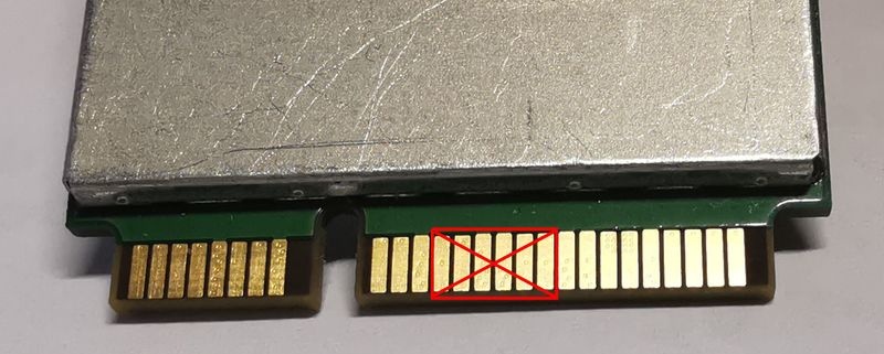
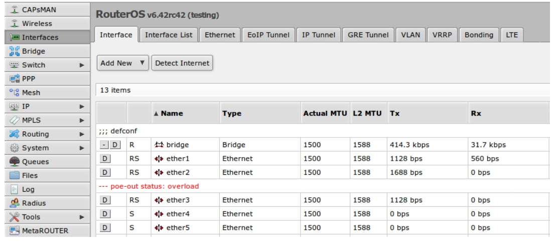
| Property | Description |
|---|---|
| dei-only (yes | no; Default: no) | Map only packets with DEI (formerly CFI) bit set in the VLAN header. |
| map (name; Default: default) | The name of the mapping table. |
| profile (name; Default: ) | The name of the QoS profile to assign to the matched packets. |
| pcp (integer: 0..7; Default: 0) | Minimum VLAN priority (PCP) value for the lookup. |
DSCP Map
Sub-menu: /interface/ethernet/switch/qos/map/ip
Matches DSCP values to QoS profiles.
| Property | Description |
|---|---|
| dscp (integer: 0..63; Default: 0) | Minimum DSCP value for the lookup. |
| map (name; Default: default) | The name of the mapping table. If not set, the standard (built-in) mapping table gets altered. |
| profile (name; Default: ) | The name of the QoS profile to assign to the matched packets. |
Transmission Manager
Sub-menu: /interface/ethernet/switch/qos/tx-manager
Transmission (Tx) Manager controls packet enqueuing for transmission and packet tx order. Different switch ports can be assigned to different Tx managers. The maximum number of hardware Tx managers depends on the switch chip model (usually - 8).
| Property | Description |
|---|---|
| ecn (yes | no; Default: no) | Enables/disables ECN marking of the transmitted packets. |
| name (string; Default: ) | The user-defined name of the Tx Manager |
Transmission Queue Scheduler
Sub-menu: /interface/ethernet/switch/qos/tx-manager/queue
Each port has eight Tx queues. The assigned Tx Manager controls packet enqueuing and schedules transmission orders. Each queue can have either strict priority (where packets with the highest traffic class are always transmitted first) or grouped together for a weighted round-robin tx schedule.
Creating a Tx Manager automatically creates all eight respective queue schedulers.
Changing any properties of Tx manager or queues completely halts traffic enqueueing and transmission during the offload process. Temporary packet loss is expected while the device is forwarding traffic.
| Property | Description |
|---|---|
| tx-manager (name; read-only) | The linked Tx Manager |
| traffic-class (integer: 0..7; read-only) | The traffic class (tc0..tc7) and the respective port queue (queue0..queue7) that the scheduler controls. |
| schedule (strict-priority | high-priority-group | low-priority-group ) |
|
| weight (integer: 0..255; Default: 1) | The weight value for the traffic class if it is a member of a schedule group. The field is not used in the case of strict priority schedule. |
| queue-buffers (integer; Default: auto) | Per-queue buffer pool. The maximum number of packets that can be assigned to the queue (per each assigned port). |
| use-shared-buffers (yes | no) | Allow the queue to use the shared buffer pool when queue-buffers are full. If the queue is full and the shared buffers are disabled, the packet gets dropped. If the shared buffers are enabled, the queue may use up to shared-packet-cap or shared-poolX-packet-cap (see QoS Settings for details) packets from the shared pool. |
| shared-pool-index (integer; Default: 0) | The shared pool index for the queue to use. Relevant only if use-shared-buffers=yes and the device supports multiple shared pools. |
| wred (yes | no; Default: no) | Enables/disables Weighted Random Early Detection for the given queue. |
Priority-based Flow Control (PFC)
Sub-menu: /interface/ethernet/switch/qos/priority-flow-control
PFC configuration is organized in profiles. Different switch ports can be assigned to different PFC profiles. The maximum number of hardware Tx managers depends on the switch chip model. The builtin profile named "disabled" cannot be changed.
| Property | Description |
|---|---|
| name (string; Default: ) | The user-defined name of the PFC profile |
| pause-threshold (percent: 0%..100% | bytes | auto; Default: auto) | Transmits a pause frame (XOFF) when the total size of enqueued packets reaches this threshold. Enqueued packets are counted per ingress port. Applies only when tx=yes. The value can be given either explicitly in bytes or percent of the respective shared pool size (shared-poolX-byte-cap). |
| resume-threshold (percent: 0%..100% | bytes | auto; Default: auto) | Transmits a resume frame (XON) when the total size of enqueued packets drops down to this threshold. Enqueued packets are counted per ingress port. Applies only when tx=yes. The value can be given either explicitly in bytes or percent of the respective shared pool size (shared-poolX-byte-cap). |
| rx (yes | no; Default: no) | Enables receiving of PFC frames. The received PFC frame pauses the specific priority queues on the port that received the PFC frame for the duration specified by the PFC frame. Disabling rx disables queue pausing. |
| traffic-class (integer array: 0..7) | The list of PFC-enabled traffic classes. |
| tx (yes | no; Default: no) | Enables transmition of PFC frames. |
Page edited by Oskars K.
- Introduction
- Internet Key Exchange Protocol (IKE)
- Authentication Header (AH)
- Encapsulating Security Payload (ESP)
- Policies
- Proposals
- Groups
- Peers
- Identities
- Active Peers
- Mode configs
- Installed SAs
- Keys
- Settings
- Application Guides
- Application examples
- Site to Site IPsec (IKEv1) tunnel
- Site to Site GRE tunnel over IPsec (IKEv2) using DNS
- Road Warrior setup using IKEv2 with RSA authentication
- Road Warrior setup using IKEv2 with EAP-MSCHAPv2 authentication handled by User Manager (RouterOS v7)
- Basic L2TP/IPsec setup
- Troubleshooting/FAQ
Introduction
Internet Protocol Security (IPsec) is a set of protocols defined by the Internet Engineering Task Force (IETF) to secure packet exchange over unprotected IP/IPv6 networks such as the Internet.
IPsec protocol suite can be divided into the following groups:
- Internet Key Exchange (IKE) protocols. Dynamically generates and distributes cryptographic keys for AH and ESP.
- Authentication Header (AH) RFC 4302
- Encapsulating Security Payload (ESP) RFC 4303
Internet Key Exchange Protocol (IKE)
The Internet Key Exchange (IKE) is a protocol that provides authenticated keying material for the Internet Security Association and Key Management Protocol (ISAKMP) framework. There are other key exchange schemes that work with ISAKMP, but IKE is the most widely used one. Together they provide means for authentication of hosts and automatic management of security associations (SA).
Most of the time IKE daemon is doing nothing. There are two possible situations when it is activated:
There is some traffic caught by a policy rule which needs to become encrypted or authenticated, but the policy doesn't have any SAs. The policy notifies the IKE daemon about that, and the IKE daemon initiates a connection to a remote host. IKE daemon responds to remote connection. In both cases, peers establish a connection and execute 2 phases:
- Phase 1 - The peers agree upon algorithms they will use in the following IKE messages and authenticate. The keying material used to derive keys for all SAs and to protect following ISAKMP exchanges between hosts is generated also. This phase should match the following settings:
- authentication method
- DH group
- encryption algorithm
- exchange mode
- hash algorithm
- NAT-T
- DPD and lifetime (optional)
- Phase 2 - The peers establish one or more SAs that will be used by IPsec to encrypt data. All SAs established by the IKE daemon will have lifetime values (either limiting time, after which SA will become invalid, or the amount of data that can be encrypted by this SA, or both). This phase should match the following settings:
- IPsec protocol
- mode (tunnel or transport)
- authentication method
- PFS (DH) group
- lifetime
There are two lifetime values - soft and hard. When SA reaches its soft lifetime threshold, the IKE daemon receives a notice and starts another phase 2 exchange to replace this SA with a fresh one. If SA reaches a hard lifetime, it is discarded.
Phase 1 is not re-keyed if DPD is disabled when the lifetime expires, only phase 2 is re-keyed. To force phase 1 re-key, enable DPD.
PSK authentication was known to be vulnerable against Offline attacks in "aggressive" mode, however recent discoveries indicate that offline attack is possible also in the case of "main" and "ike2" exchange modes. A general recommendation is to avoid using the PSK authentication method.
IKE can optionally provide a Perfect Forward Secrecy (PFS), which is a property of key exchanges, that, in turn, means for IKE that compromising the long term phase 1 key will not allow to easily gain access to all IPsec data that is protected by SAs established through this phase 1. It means an additional keying material is generated for each phase 2.
The generation of keying material is computationally very expensive. Exempli Gratia, the use of the modp8192 group can take several seconds even on a very fast computer. It usually takes place once per phase 1 exchange, which happens only once between any host pair and then is kept for a long time. PFS adds this expensive operation also to each phase 2 exchange.
Diffie-Hellman Groups
Diffie-Hellman (DH) key exchange protocol allows two parties without any initial shared secret to create one securely. The following Modular Exponential (MODP) and ECP Diffie-Hellman (also known as "Oakley") Groups are supported:
| Diffie-Hellman Group | Name | Reference |
|---|---|---|
| Group 1 | 768 bits MODP group | RFC 2409 |
| Group 2 | 1024 bits MODP group | RFC 2409 |
| Group 5 | 1536 bits MODP group | RFC 3526 |
| Group 14 | 2048 bits MODP group | RFC 3526 |
| Group 15 | 3072 bits MODP group | RFC 3526 |
| Group 16 | 4096 bits MODP group | RFC 3526 |
| Group 17 | 6144 bits MODP group | RFC 3526 |
| Group 18 | 8192 bits MODP group | RFC 3526 |
| Group 19 | 256 bits random ECP group | RFC 5903 |
| Group 20 | 384 bits random ECP group | RFC 5903 |
| Group 21 | 521 bits random ECP group | RFC 5903 |
More on standards can be found here.
Larger DH groups offer better security but require more CPU power. Here are a few commonly used DH groups with varying levels of security and CPU impact:
DH Group 14 (2048-bit) - Provides a reasonable balance between security and CPU usage. It offers 2048-bit key exchange, which is considered secure for most applications today and is widely supported.
DH Group 5 (1536-bit) - Offers a slightly lower level of security compared to DH Group 14 but has a lower CPU impact due to the smaller key size. It is still considered secure for many scenarios.
DH Group 2 (1024-bit) - Should be used with caution because it provides the least security among commonly used groups. It has a lower CPU impact but is susceptible to attacks, especially as computational power increases. It's generally not recommended for new deployments.
For optimal security, it's advisable to use DH Group 19. It's considered fast and secure. However, DH Group 14 might give large load for your router, DH Group 5 can be a reasonable compromise between security and performance. DH Group 2 should generally be avoided unless you have legacy devices that require it.
The correct way of calculating security for your network infrastructure would be to choose how many bits of security you want and you could see how long it would require to decrypt your data, then you have to choose algorithms. Please see information for reference https://www.keylength.com/en/4/
IKE Traffic
To avoid problems with IKE packets hit some SPD rule and require to encrypt it with not yet established SA (that this packet perhaps is trying to establish), locally originated packets with UDP source port 500 are not processed with SPD. The same way packets with UDP destination port 500 that are to be delivered locally are not processed in incoming policy checks.
Setup Procedure
To get IPsec to work with automatic keying using IKE-ISAKMP you will have to configure policy, peer, and proposal (optional) entries.
IPsec is very sensitive to time changes. If both ends of the IPsec tunnel are not synchronizing time equally(for example, different NTP servers not updating time with the same timestamp), tunnels will break and will have to be established again.
EAP Authentication methods
| Outer Auth | Inner Auth |
|---|---|
| EAP-GTC | |
| EAP-MD5 | |
| EAP-MSCHAPv2 | |
| EAP-PEAPv0 | EAP-MSCHAPv2 |
| EAP-SIM | |
| EAP-TLS | |
| EAP-TTLS | PAP |
EAP-TLS on Windows is called "Smart Card or other certificates".
If using IPsec with certificate X.509 must contain "SubjectKeyIdentifier" extension, which is supported only in version 3.
Using ed25519 - authentication is not yet supported.
Authentication Header (AH)
AH is a protocol that provides authentication of either all or part of the contents of a datagram through the addition of a header that is calculated based on the values in the datagram. What parts of the datagram are used for the calculation, and the placement of the header depends on whether tunnel or transport mode is used.
The presence of the AH header allows to verify the integrity of the message but doesn't encrypt it. Thus, AH provides authentication but not privacy. Another protocol (ESP) is considered superior, it provides data privacy and also its own authentication method.
RouterOS supports the following authentication algorithms for AH:
- SHA2 (256, 512)
- SHA1
- MD5
Transport mode
In transport mode, the AH header is inserted after the IP header. IP data and header is used to calculate authentication value. IP fields that might change during transit, like TTL and hop count, are set to zero values before authentication.
Tunnel mode
In tunnel mode, the original IP packet is encapsulated within a new IP packet. All of the original IP packets are authenticated.
Encapsulating Security Payload (ESP)
Encapsulating Security Payload (ESP) uses shared key encryption to provide data privacy. ESP also supports its own authentication scheme like that used in AH.
ESP packages its fields in a very different way than AH. Instead of having just a header, it divides its fields into three components:
- ESP Header - Comes before the encrypted data and its placement depends on whether ESP is used in transport mode or tunnel mode.
- ESP Trailer - This section is placed after the encrypted data. It contains padding that is used to align the encrypted data.
- ESP Authentication Data - This field contains an Integrity Check Value (ICV), computed in a manner similar to how the AH protocol works, for when ESP's optional authentication feature is used.
Transport mode
In transport mode, the ESP header is inserted after the original IP header. ESP trailer and authentication value are added to the end of the packet. In this mode only the IP payload is encrypted and authenticated, the IP header is not secured.
![]()
Tunnel mode
In tunnel mode, an original IP packet is encapsulated within a new IP packet thus securing IP payload and IP header.
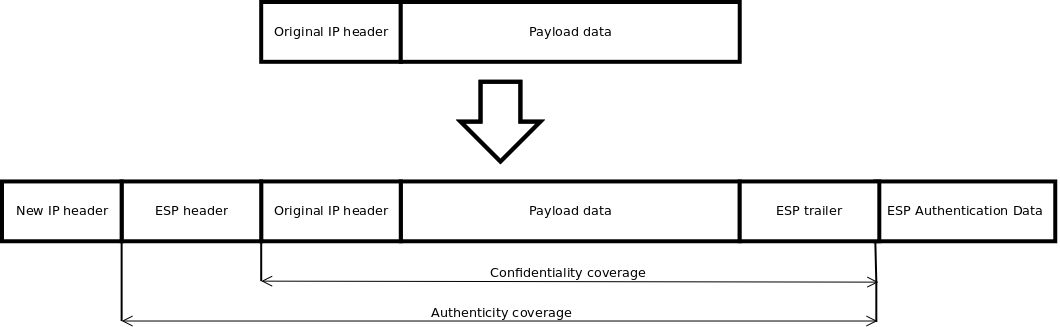
Encryption algorithms
RouterOS ESP supports various encryption and authentication algorithms.
Authentication:
- MD5
- SHA1
- SHA2 (256-bit, 512-bit)
Encryption:
- AES - 128-bit, 192-bit, and 256-bit key AES-CBC, AES-CTR, and AES-GCM algorithms;
- Blowfish - added since v4.5
- Twofish - added since v4.5
- Camellia - 128-bit, 192-bit, and 256-bit key Camellia encryption algorithm added since v4.5
- DES - 56-bit DES-CBC encryption algorithm;
- 3DES - 168-bit DES encryption algorithm;
Hardware acceleration
Hardware acceleration allows doing a faster encryption process by using a built-in encryption engine inside the CPU.
List of devices with hardware acceleration is available here
| CPU | DES and 3DES | AES-CBC | AES-CTR | AES-GCM | ||||||||||||
|---|---|---|---|---|---|---|---|---|---|---|---|---|---|---|---|---|
| MD5 | SHA1 | SHA256 | SHA512 | MD5 | SHA1 | SHA256 | SHA512 | MD5 | SHA1 | SHA256 | SHA512 | MD5 | SHA1 | SHA256 | SHA512 | |
| 88F7040 | no | yes | yes | yes | no | yes | yes | yes | no | yes | yes | yes | no | yes | yes | yes |
| AL21400 | yes | yes | yes | yes | yes | yes | yes | yes | yes | yes | yes | yes | yes | yes | yes | yes |
| AL32400 | yes | yes | yes | yes | yes | yes | yes | yes | yes | yes | yes | yes | yes | yes | yes | yes |
| AL52400 | yes | yes | yes | yes | yes | yes | yes | yes | yes | yes | yes | yes | yes | yes | yes | yes |
| AL73400 | yes | yes | yes | yes | yes | yes | yes | yes | yes | yes | yes | yes | yes | yes | yes | yes |
| IPQ-4018 / IPQ-4019 | no | yes | yes | no | no | yes* | yes* | no | no | yes* | yes* | no | no | no | no | no |
| IPQ-5018 | yes | yes | yes | no | yes | yes | yes | no | yes | yes | yes | no | no | no | no | no |
| IPQ-6010 | no | no | no | no | no | yes | yes | yes | no | yes | yes | yes | no | yes | yes | yes |
| IPQ-8064 | no | yes | yes | no | no | yes* | yes* | no | no | yes* | yes* | no | no | no | no | no |
| MT7621A | yes**** | yes**** | yes**** | no | yes | yes | yes | no | no | no | no | no | no | no | no | no |
| P1023NSN5CFB | no | no | no | no | yes** | yes** | yes** | yes** | no | no | no | no | no | no | no | no |
| P202ASSE2KFB | yes | yes | yes | no | yes | yes | yes | yes | no | no | no | no | no | no | no | no |
| PPC460GT | no | no | no | no | yes*** | yes*** | yes*** | yes*** | yes*** | yes*** | yes*** | yes*** | no | no | no | no |
| TLR4 (TILE) | yes | yes | yes | no | yes | yes | yes | no | yes | yes | yes | no | no | no | no | no |
| x86 (AES-NI) | no | no | no | no | yes*** | yes*** | yes*** | yes*** | yes*** | yes*** | yes*** | yes*** | yes*** | yes*** | yes*** | yes*** |
* supported only 128 bit and 256 bit key sizes
** only manufactured since 2016, serial numbers that begin with number 5 and 7
*** AES-CBC and AES-CTR only encryption is accelerated, hashing done in software
**** DES is not supported, only 3DES and AES-CBC
IPsec throughput results of various encryption and hash algorithm combinations are published on the MikroTik products page.
Policies
The policy table is used to determine whether security settings should be applied to a packet.
Properties
| Property | Description |
|---|---|
| action (discard | encrypt | none; Default: encrypt) | Specifies what to do with the packet matched by the policy.
|
| comment (string; Default: ) | Short description of the policy. |
| disabled (yes | no; Default: no) | Whether a policy is used to match packets. |
| dst-address (IP/IPv6 prefix; Default: 0.0.0.0/32) | Destination address to be matched in packets. Applicable when tunnel mode (tunnel=yes) or template (template=yes) is used. |
| dst-port (integer:0..65535 | any; Default: any) | Destination port to be matched in packets. If set to any all ports will be matched. |
| group (string; Default: default) | Name of the policy group to which this template is assigned. |
| ipsec-protocols (ah | esp; Default: esp) | Specifies what combination of Authentication Header and Encapsulating Security Payload protocols you want to apply to matched traffic. |
| level (require | unique | use; Default: require) | Specifies what to do if some of the SAs for this policy cannot be found:
|
| peer (string; Default: ) | Name of the peer on which the policy applies. |
| proposal (string; Default: default) | Name of the proposal template that will be sent by IKE daemon to establish SAs for this policy. |
| protocol (all | egp | ggp| icmp | igmp | ...; Default: all) | IP packet protocol to match. |
| src-address (ip/ipv6 prefix; Default: 0.0.0.0/32) | Source address to be matched in packets. Applicable when tunnel mode (tunnel=yes) or template (template=yes) is used. |
| src-port (any | integer:0..65535; Default: any) | Source port to be matched in packets. If set to any all ports will be matched. |
| template (yes | no; Default: no) | Creates a template and assigns it to a specified policy group. Following parameters are used by template:
|
| tunnel (yes | no; Default: no) | Specifies whether to use tunnel mode. |
Read-only properties
| Property | Description |
|---|---|
| active (yes | no) | Whether this policy is currently in use. |
| default (yes | no) | Whether this is a default system entry. |
| dynamic (yes | no) | Whether this is a dynamically added or generated entry. |
| invalid (yes | no) | Whether this policy is invalid - the possible cause is a duplicate policy with the same src-address and dst-address. |
| ph2-count (integer) | A number of active phase 2 sessions associated with the policy. |
| ph2-state (expired | no-phase2 | established) | Indication of the progress of key establishing. |
| sa-dst-address (ip/ipv6 address; Default: ::) | SA destination IP/IPv6 address (remote peer). |
| sa-src-address (ip/ipv6 address; Default: ::) | SA source IP/IPv6 address (local peer). |
Policy order is important starting from v6.40. Now it works similarly to firewall filters where policies are executed from top to bottom (priority parameter is removed).
All packets are IPIP encapsulated in tunnel mode, and their new IP header's src-address and dst-address are set to sa-src-address and sa-dst-address values of this policy. If you do not use tunnel mode (id est you use transport mode), then only packets whose source and destination addresses are the same as sa-src-address and sa-dst-address can be processed by this policy. Transport mode can only work with packets that originate at and are destined for IPsec peers (hosts that established security associations). To encrypt traffic between networks (or a network and a host) you have to use tunnel mode.
Statistics
This menu shows various IPsec statistics and errors.
Read-only properties
| Property | Description |
|---|---|
| in-errors (integer) | All inbound errors that are not matched by other counters. |
| in-buffer-errors (integer) | No free buffer. |
| in-header-errors (integer) | Header error. |
| in-no-states (integer) | No state is found i.e. either inbound SPI, address, or IPsec protocol at SA is wrong. |
| in-state-protocol-errors (integer) | Transformation protocol-specific error, for example, SA key is wrong or hardware accelerator is unable to handle the number of packets. |
| in-state-mode-errors (integer) | Transformation mode-specific error. |
| in-state-sequence-errors (integer) | A sequence number is out of a window. |
| in-state-expired (integer) | The state is expired. |
| in-state-mismatches (integer) | The state has a mismatched option, for example, the UDP encapsulation type is mismatched. |
| in-state-invalid (integer) | The state is invalid. |
| in-template-mismatches (integer) | No matching template for states, e.g. inbound SAs are correct but the SP rule is wrong. A possible cause is a mismatched sa-source or sa-destination address. |
| in-no-policies (integer) | No policy is found for states, e.g. inbound SAs are correct but no SP is found. |
| in-policy-blocked (integer) | Policy discards. |
| in-policy-errors (integer) | Policy errors. |
| out-errors (integer) | All outbound errors that are not matched by other counters. |
| out-bundle-errors (integer) | Bundle generation error. |
| out-bundle-check-errors (integer) | Bundle check error. |
| out-no-states (integer) | No state is found. |
| out-state-protocol-errors (integer) | Transformation protocol specific error. |
| out-state-mode-errors (integer) | Transformation mode-specific error. |
| out-state-sequence-errors (integer) | Sequence errors, for example, sequence number overflow. |
| out-state-expired (integer) | The state is expired. |
| out-policy-blocked (integer) | Policy discards. |
| out-policy-dead (integer) | The policy is dead. |
| out-policy-errors (integer) | Policy error. |
Proposals
Proposal information that will be sent by IKE daemons to establish SAs for certain policies.
Properties
| Property | Description |
|---|---|
| auth-algorithms (md5|null|sha1|sha256|sha512; Default: sha1) | Allowed algorithms for authorization. SHA (Secure Hash Algorithm) is stronger but slower. MD5 uses a 128-bit key, sha1-160bit key. |
| comment (string; Default: ) | |
| disabled (yes | no; Default: no) | Whether an item is disabled. |
| enc-algorithms (null|des|3des|aes-128-cbc|aes-128-cbc|aes-128gcm|aes-192-cbc|aes-192-ctr|aes-192-gcm|aes-256-cbc|aes-256-ctr|aes-256-gcm|blowfish|camellia-128|camellia-192|camellia-256|twofish; Default: aes-256-cbc,aes-192-cbc,aes-128-cbc) | Allowed algorithms and key lengths to use for SAs. |
| lifetime (time; Default: 30m) | How long to use SA before throwing it out. |
| name (string; Default: ) | |
| pfs-group (ecp256 | ecp384 | ecp521 | modp768 | modp1024 | modp1536 | modp2048 | modp3072 | modp4096 | modp6144 | modp8192 | none; Default: modp1024) | The diffie-Helman group used for Perfect Forward Secrecy. |
Read-only properties
| Property | Description |
|---|---|
| default (yes | no) | Whether this is a default system entry. |
Groups
In this menu, it is possible to create additional policy groups used by policy templates.
Properties
| Property | Description |
|---|---|
| name (string; Default: ) | |
| comment (string; Default: ) |
Peers
Peer configuration settings are used to establish connections between IKE daemons. This connection then will be used to negotiate keys and algorithms for SAs. Exchange mode is the only unique identifier between the peers, meaning that there can be multiple peer configurations with the same remote-address as long as a different exchange-mode is used.
Properties
| Property | Description |
|---|---|
| address (IP/IPv6 Prefix; Default: 0.0.0.0/0) | If the remote peer's address matches this prefix, then the peer configuration is used in authentication and establishment of Phase 1. If several peer's addresses match several configuration entries, the most specific one (i.e. the one with the largest netmask) will be used. |
| comment (string; Default: ) | Short description of the peer. |
| disabled (yes | no; Default: no) | Whether peer is used to matching remote peer's prefix. |
| exchange-mode (aggressive | base | main | ike2; Default: main) | Different ISAKMP phase 1 exchange modes according to RFC 2408. the main mode relaxes rfc2409 section 5.4, to allow pre-shared-key authentication in the main mode. ike2 mode enables Ikev2 RFC 7296. Parameters that are ignored by IKEv2 proposal-check, compatibility-options, lifebytes, dpd-maximum-failures, nat-traversal. |
| local-address (IP/IPv6 Address; Default: ) | Routers local address on which Phase 1 should be bounded to. |
| name (string; Default: ) | |
| passive (yes | no; Default: no) | When a passive mode is enabled will wait for a remote peer to initiate an IKE connection. The enabled passive mode also indicates that the peer is xauth responder, and disabled passive mode - xauth initiator. When a passive mode is a disabled peer will try to establish not only phase1 but also phase2 automatically, if policies are configured or created during the phase1. |
| port (integer:0..65535; Default: 500) | Communication port used (when a router is an initiator) to connect to remote peer in cases if remote peer uses the non-default port. |
| profile (string; Default: default) | Name of the profile template that will be used during IKE negotiation. |
| send-initial-contact (yes | no; Default: yes) | Specifies whether to send "initial contact" IKE packet or wait for remote side, this packet should trigger the removal of old peer SAs for current source address. Usually, in road warrior setups clients are initiators and this parameter should be set to no. Initial contact is not sent if modecfg or xauth is enabled for ikev1. |
Read-only properties
| Property | Description |
|---|---|
| dynamic (yes | no) | Whether this is a dynamically added entry by a different service (e.g L2TP). |
| responder (yes | no) | Whether this peer will act as a responder only (listen to incoming requests) and not initiate a connection. |
Profiles
Profiles define a set of parameters that will be used for IKE negotiation during Phase 1. These parameters may be common with other peer configurations.
Properties
| Property | Description |
|---|---|
| dh-group (modp768 | modp1024 | modp1536 | modp2048 | modp3072 | modp4096 | modp6144 | modp8192 | ecp256 | ecp384 | ecp521; Default: modp1024,modp2048) | Diffie-Hellman group (cipher strength) |
| dpd-interval (time | disable-dpd; Default: 2m) | Dead peer detection interval. If set to disable-dpd, dead peer detection will not be used. |
| dpd-maximum-failures (integer: 1..100; Default: 5) | Maximum count of failures until peer is considered to be dead. Applicable if DPD is enabled. |
| enc-algorithm (3des | aes-128 | aes-192 | aes-256 | blowfish | camellia-128 | camellia-192 | camellia-256 | des; Default: aes-128) | List of encryption algorithms that will be used by the peer. |
| hash-algorithm (md5 | sha1 | sha256 | sha512; Default: sha1) | Hashing algorithm. SHA (Secure Hash Algorithm) is stronger, but slower. MD5 uses 128-bit key, sha1-160bit key. |
| lifebytes (Integer: 0..4294967295; Default: 0) | Phase 1 lifebytes is used only as administrative value which is added to proposal. Used in cases if remote peer requires specific lifebytes value to establish phase 1. |
| lifetime (time; Default: 1d) | Phase 1 lifetime: specifies how long the SA will be valid. |
| name (string; Default: ) | |
| nat-traversal (yes | no; Default: yes) | Use Linux NAT-T mechanism to solve IPsec incompatibility with NAT routers between IPsec peers. This can only be used with ESP protocol (AH is not supported by design, as it signs the complete packet, including the IP header, which is changed by NAT, rendering AH signature invalid). The method encapsulates IPsec ESP traffic into UDP streams in order to overcome some minor issues that made ESP incompatible with NAT. |
| proposal-check (claim | exact | obey | strict; Default: obey) | Phase 2 lifetime check logic:
|
Identities
Identities are configuration parameters that are specific to the remote peer. The main purpose of identity is to handle authentication and verify the peer's integrity.
Properties
| Property | Description |
|---|---|
| auth-method (digital-signature | eap | eap-radius | pre-shared-key | pre-shared-key-xauth | rsa-key | rsa-signature-hybrid; Default: pre-shared-key) | Authentication method:
|
| certificate (string; Default: ) | Name of a certificate listed in System/Certificates (signing packets; the certificate must have the private key). Applicable if digital signature authentication method (auth-method=digital-signature) or EAP (auth-method=eap) is used. |
| comment (string; Default: ) | Short description of the identity. |
| disabled (yes | no; Default: no) | Whether identity is used to match remote peers. |
| eap-methods (eap-mschapv2 | eap-peap | eap-tls | eap-ttls; Default: eap-tls) | All EAP methods requires whole certificate chain including intermediate and root CA certificates to be present in System/Certificates menu. Also, the username and password (if required by the authentication server) must be specified. Multiple EAP methods may be specified and will be used in a specified order. Currently supported EAP methods:
|
| generate-policy (no | port-override | port-strict; Default: no) | Allow this peer to establish SA for non-existing policies. Such policies are created dynamically for the lifetime of SA. Automatic policies allows, for example, to create IPsec secured L2TP tunnels, or any other setup where remote peer's IP address is not known at the configuration time.
|
| key (string; Default: ) | Name of the private key from keys menu. Applicable if RSA key authentication method (auth-method=rsa-key) is used. |
| match-by (remote-id | certificate; Default: remote-id) | Defines the logic used for peer's identity validation.
|
| mode-config (none | *request-only | string; Default: none) | Name of the configuration parameters from mode-config menu. When parameter is set mode-config is enabled. |
| my-id (auto | address | fqdn | user-fqdn | key-id; Default: auto) | On initiator, this controls what ID_i is sent to the responder. On responder, this controls what ID_r is sent to the initiator. In IKEv2, responder also expects this ID in received ID_r from initiator.
|
| notrack-chain (string; Default: ) | Adds IP/Firewall/Raw rules matching IPsec policy to a specified chain. Use together with generate-policy. |
| password (string; Default: ) | XAuth or EAP password. Applicable if pre-shared key with XAuth authentication method (auth-method=pre-shared-key-xauth) or EAP (auth-method=eap) is used. |
| peer (string; Default: ) | Name of the peer on which the identity applies. |
| policy-template-group (none | string; Default: default) | If generate-policy is enabled, traffic selectors are checked against templates from the same group. If none of the templates match, Phase 2 SA will not be established. |
| remote-certificate (string; Default: ) | Name of a certificate (listed in System/Certificates) for authenticating the remote side (validating packets; no private key required). If a remote-certificate is not specified then the received certificate from a remote peer is used and checked against CA in the certificate menu. Proper CA must be imported in a certificate store. If remote-certificate and match-by=certificate is specified, only the specific client certificate will be matched. Applicable if digital signature authentication method (auth-method=digital-signature) is used. |
| remote-id (auto | fqdn | user-fqdn | key-id | ignore; Default: auto) | This parameter controls what ID value to expect from the remote peer. Note that all types except for ignoring will verify remote peer's ID with a received certificate. In case when the peer sends the certificate name as its ID, it is checked against the certificate, else the ID is checked against Subject Alt. Name.
* Wildcard key ID matching is not supported, for example remote-id="key-id:CN=*.domain.com" |
| remote-key (string; Default: ) | Name of the public key from keys menu. Applicable if RSA key authentication method (auth-method=rsa-key) is used. |
| secret (string; Default: ) | Secret string. If it starts with '0x', it is parsed as a hexadecimal value. Applicable if pre-shared key authentication method (auth-method=pre-shared-key and auth-method=pre-shared-key-xauth) is used. |
| username (string; Default: ) | XAuth or EAP username. Applicable if pre-shared key with XAuth authentication method (auth-method=pre-shared-key-xauth) or EAP (auth-method=eap) is used. |
Read only properties
| Property | Description |
|---|---|
| dynamic (yes | no) | Whether this is a dynamically added entry by a different service (e.g L2TP). |
Active Peers
This menu provides various statistics about remote peers that currently have established phase 1 connection.
Read only properties
| Property | Description |
|---|---|
| dynamic-address (ip/ipv6 address) | Dynamically assigned an IP address by mode config |
| last-seen (time) | Duration since the last message received by this peer. |
| local-address (ip/ipv6 address) | Local address on the router used by this peer. |
| natt-peer (yes | no) | Whether NAT-T is used for this peer. |
| ph2-total (integer) | The total amount of active IPsec security associations. |
| remote-address (ip/ipv6 address) | The remote peer's ip/ipv6 address. |
| responder (yes | no) | Whether the connection is initiated by a remote peer. |
| rx-bytes (integer) | The total amount of bytes received from this peer. |
| rx-packets (integer) | The total amount of packets received from this peer. |
| side (initiator | responder) | Shows which side initiated the Phase1 negotiation. |
| state (string) | State of phase 1 negotiation with the peer. For example, when phase1 and phase 2 are negotiated it will show state "established". |
| tx-bytes (integer) | The total amount of bytes transmitted to this peer. |
| tx-packets (integer) | The total amount of packets transmitted to this peer. |
| uptime (time) | How long peers are in an established state. |
Commands
| Property | Description |
|---|---|
| kill-connections () | Manually disconnects all remote peers. |
Mode configs
ISAKMP and IKEv2 configuration attributes are configured in this menu.
Properties
| Property | Description |
|---|---|
| address (none | string; Default: ) | Single IP address for the initiator instead of specifying a whole address pool. |
| address-pool (none | string; Default: ) | Name of the address pool from which the responder will try to assign address if mode-config is enabled. |
| address-prefix-length (integer [1..32]; Default: ) | Prefix length (netmask) of the assigned address from the pool. |
| comment (string; Default: ) | |
| name (string; Default: ) | |
| responder (yes | no; Default: no) | Specifies whether the configuration will work as an initiator (client) or responder (server). The initiator will request for mode-config parameters from the responder. |
| split-dns | List of DNS names that will be resolved using a system-dns=yes or static-dns= setting. |
| split-include (list of IP prefix; Default: ) | List of subnets in CIDR format, which to tunnel. Subnets will be sent to the peer using the CISCO UNITY extension, a remote peer will create specific dynamic policies. |
| src-address-list (address list; Default: ) | Specifying an address list will generate dynamic source NAT rules. This parameter is only available with responder=no. A roadWarrior client with NAT |
| static-dns (list of IP; Default: ) | Manually specified DNS server's IP address to be sent to the client. |
| system-dns (yes | no; Default: ) | When this option is enabled DNS addresses will be taken from /ip dns. |
Read-only properties
| Property | Description |
|---|---|
| default (yes | no) | Whether this is a default system entry. |
Not all IKE implementations support multiple split networks provided by the split-include option.
If RouterOS client is initiator, it will always send CISCO UNITY extension, and RouterOS supports only split-include from this extension.
Both attributes Cisco Unity Split DNS (attribute type 28675) and RFC8598 (attribute type 25) are supported, ROS will answer to these attributes but only as responder.
It is not possible to use system-dns and static-dns at the same time, ROS can use only one DNS.
Installed SAs
This menu provides information about installed security associations including the keys.
Read-only properties
| Property | Description |
|---|---|
| AH (yes | no) | Whether AH protocol is used by this SA. |
| ESP (yes | no) | Whether ESP protocol is used by this SA. |
| add-lifetime (time/time) | Added lifetime for the SA in format soft/hard:
|
| addtime (time) | Date and time when this SA was added. |
| auth-algorithm (md5 | null | sha1 | ...) | Currently used authentication algorithm. |
| auth-key (string) | Used authentication key. |
| current-bytes (64-bit integer) | A number of bytes seen by this SA. |
| dst-address (IP) | The destination address of this SA. |
| enc-algorithm (des | 3des | aes-cbc | ...) | Currently used encryption algorithm. |
| enc-key (string) | Used encryption key. |
| enc-key-size (number) | Used encryption key length. |
| expires-in (yes | no) | Time left until rekeying. |
| hw-aead (yes | no) | Whether this SA is hardware accelerated. |
| replay (integer) | Size of replay window in bytes. |
| spi (string) | Security Parameter Index identification tag |
| src-address (IP) | The source address of this SA. |
| state (string) | Shows the current state of the SA ("mature", "dying" etc) |
Commands
| Property | Description |
|---|---|
| flush () | Manually removes all installed security associations. |
Keys
This menu lists all imported public and private keys, that can be used for peer authentication. Menu has several commands to work with keys.
Properties
| Property | Description |
|---|---|
| name (string; Default: ) |
Read-only properties
| Property | Description |
|---|---|
| key-size (1024 | 2048 | 4096) | Size of this key. |
| private-key (yes | no) | Whether this is a private key. |
| rsa (yes | no) | Whether this is an RSA key. |
Commands
| Property | Description |
|---|---|
| export-pub-key (file-name; key) | Export public key to file from one of existing private keys. |
| generate-key (key-size; name) | Generate a private key. Takes two parameters, name of the newly generated key and key size 1024,2048 and 4096. |
| import (file-name; name) | Import key from file. |
Settings
| Property | Description |
|---|---|
| accounting (yes | no; Default: ) | Whether to send RADIUS accounting requests to a RADIUS server. Applicable if EAP Radius (auth-method=eap-radius) or pre-shared key with XAuth authentication method (auth-method=pre-shared-key-xauth) is used. |
| interim-update (time; Default: ) | The interval between each consecutive RADIUS accounting Interim update. Accounting must be enabled. |
| xauth-use-radius (yes | no; Default: ) | Whether to use Radius client for XAuth users or not. Property is only applicable to peers using the IKEv1 exchange mode. |
Application Guides
RoadWarrior client with NAT
Consider setup as illustrated below. RouterOS acts as a RoadWarrior client connected to Office allowing access to its internal resources.
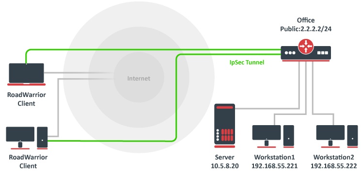
A tunnel is established, a local mode-config IP address is received and a set of dynamic policies are generated.
[admin@mikrotik] > ip ipsec policy print
Flags: T - template, X - disabled, D - dynamic, I - invalid, A - active, * - default
0 T * group=default src-address=::/0 dst-address=::/0 protocol=all proposal=default template=yes

1 DA src-address=192.168.77.254/32 src-port=any dst-address=10.5.8.0/24 dst-port=any protocol=all
action=encrypt level=unique ipsec-protocols=esp tunnel=yes sa-src-address=10.155.107.8
sa-dst-address=10.155.107.9 proposal=default ph2-count=1

2 DA src-address=192.168.77.254/32 src-port=any dst-address=192.168.55.0/24 dst-port=any protocol=all
action=encrypt level=unique ipsec-protocols=esp tunnel=yes sa-src-address=10.155.107.8
sa-dst-address=10.155.107.9 proposal=default ph2-count=1
Currently, only packets with a source address of 192.168.77.254/32 will match the IPsec policies. For a local network to be able to reach remote subnets, it is necessary to change the source address of local hosts to the dynamically assigned mode config IP address. It is possible to generate source NAT rules dynamically. This can be done by creating a new address list that contains all local networks that the NAT rule should be applied. In our case, it is 192.168.88.0/24.
/ip firewall address-list add address=192.168.88.0/24 list=local-RW
By specifying the address list under the mode-config initiator configuration, a set of source NAT rules will be dynamically generated.
/ip ipsec mode-config set [ find name="request-only" ] src-address-list=local-RW
When the IPsec tunnel is established, we can see the dynamically created source NAT rules for each network. Now every host in 192.168.88.0/24 is able to access Office's internal resources.
[admin@mikrotik] > ip firewall nat print
Flags: X - disabled, I - invalid, D - dynamic
0 D ;;; ipsec mode-config
chain=srcnat action=src-nat to-addresses=192.168.77.254 dst-address=192.168.55.0/24 src-address-list=local-RW

1 D ;;; ipsec mode-config
chain=srcnat action=src-nat to-addresses=192.168.77.254 dst-address=10.5.8.0/24 src-address-list=local-RW
Allow only IPsec encapsulated traffic
There are some scenarios where for security reasons you would like to drop access from/to specific networks if incoming/outgoing packets are not encrypted. For example, if we have L2TP/IPsec setup we would want to drop nonencrypted L2TP connection attempts.
There are several ways how to achieve this:
- Using IPsec policy matcher in firewall;
- Using generic IPsec policy with action set to drop and lower priority (can be used in Road Warrior setups where dynamic policies are generated);
- By setting DSCP or priority in mangle and matching the same values in firewall after decapsulation.
IPsec policy matcher
Let's set up an IPsec policy matcher to accept all packets that matched any of the IPsec policies and drop the rest:
add chain=input comment="ipsec policy matcher" in-interface=WAN ipsec-policy=in,ipsec
add action=drop chain=input comment="drop all" in-interface=WAN log=yes
IPsec policy matcher takes two parameters direction, policy. We used incoming direction and IPsec policy. IPsec policy option allows us to inspect packets after decapsulation, so for example, if we want to allow only GRE encapsulated packet from a specific source address and drop the rest we could set up the following rules:
add chain=input comment="ipsec policy matcher" in-interface=WAN ipsec-policy=in,ipsec protocol=gre src=address=192.168.33.1
add action=drop chain=input comment="drop all" in-interface=WAN log=yes
For L2TP rule set would be:
add chain=input comment="ipsec policy matcher" in-interface=WAN ipsec-policy=in,ipsec protocol=udp dst-port=1701
add action=drop chain=input protocol=udp dst-port=1701 comment="drop l2tp" in-interface=WAN log=yes
Using generic IPsec policy
The trick of this method is to add a default policy with an action drop. Let's assume we are running an L2TP/IPsec server on a public 1.1.1.1 address and we want to drop all nonencrypted L2TP:
/ip ipsec policy
add src-address=1.1.1.1 dst-address=0.0.0.0/0 sa-src-address=1.1.1.1 protocol=udp src-port=1701 tunnel=yes action=discard
Now router will drop any L2TP unencrypted incoming traffic, but after a successful L2TP/IPsec connection dynamic policy is created with higher priority than it is on default static rule, and packets matching that dynamic rule can be forwarded.
Policy order is important! For this to work, make sure the static drop policy is below the dynamic policies. Move it below the policy template if necessary.
[admin@rack2_10g1] /ip ipsec policy> print
Flags: T - template, X - disabled, D - dynamic, I - inactive, * - default
0 T * group=default src-address=::/0 dst-address=::/0 protocol=all
proposal=default template=yes

1 D src-address=1.1.1.1/32 src-port=1701 dst-address=10.5.130.71/32
dst-port=any protocol=udp action=encrypt level=require
ipsec-protocols=esp tunnel=no sa-src-address=1.1.1.1
sa-dst-address=10.5.130.71

2 src-address=1.1.1.1/32 src-port=1701 dst-address=0.0.0.0/0
dst-port=any protocol=udp action=discard level=unique
ipsec-protocols=esp tunnel=yes sa-src-address=1.1.1.1
sa-dst-address=0.0.0.0 proposal=default manual-sa=none
Manually specifying local-address parameter under Peer configuration
Using different routing table
IPsec, as any other service in RouterOS, uses the main routing table regardless of what local-address parameter is used for Peer configuration. It is necessary to apply routing marks to both IKE and IPSec traffic.
Consider the following example. There are two default routes - one in the main routing table and another in the routing table "backup". It is necessary to use the backup link for the IPsec site to site tunnel.
[admin@pair_r1] > /ip route print detail
Flags: X - disabled, A - active, D - dynamic, C - connect, S - static, r - rip, b - bgp, o - ospf, m - mme, B - blackhole, U - unreachable, P - prohibit
0 A S dst-address=0.0.0.0/0 gateway=10.155.107.1 gateway-status=10.155.107.1 reachable via ether1 distance=1 scope=30 target-scope=10 routing-mark=backup

1 A S dst-address=0.0.0.0/0 gateway=172.22.2.115 gateway-status=172.22.2.115 reachable via ether2 distance=1 scope=30 target-scope=10

2 ADC dst-address=10.155.107.0/25 pref-src=10.155.107.8 gateway=ether1 gateway-status=ether1 reachable distance=0 scope=10

3 ADC dst-address=172.22.2.0/24 pref-src=172.22.2.114 gateway=ether2 gateway-status=ether2 reachable distance=0 scope=10

4 ADC dst-address=192.168.1.0/24 pref-src=192.168.1.1 gateway=bridge-local gateway-status=ether2 reachable distance=0 scope=10

[admin@pair_r1] > /ip firewall nat print
Flags: X - disabled, I - invalid, D - dynamic
0 chain=srcnat action=masquerade out-interface=ether1 log=no log-prefix=""

1 chain=srcnat action=masquerade out-interface=ether2 log=no log-prefix=""
IPsec peer and policy configurations are created using the backup link's source address, as well as the NAT bypass rule for IPsec tunnel traffic.
/ip ipsec peer
add address=10.155.130.136/32 local-address=10.155.107.8 secret=test
/ip ipsec policy
add sa-src-address=10.155.107.8 src-address=192.168.1.0/24 dst-address=172.16.0.0/24 sa-dst-address=10.155.130.136 tunnel=yes
/ip firewall nat
add action=accept chain=srcnat src-address=192.168.1.0/24 dst-address=172.16.0.0/24 place-before=0
Currently, we see "phase1 negotiation failed due to time up" errors in the log. It is because IPsec tries to reach the remote peer using the main routing table with an incorrect source address. It is necessary to mark UDP/500, UDP/4500, and ipsec-esp packets using Mangle:
/ip firewall mangle
add action=mark-connection chain=output connection-mark=no-mark dst-address=10.155.130.136 dst-port=500,4500 new-connection-mark=ipsec passthrough=yes protocol=udp
add action=mark-connection chain=output connection-mark=no-mark dst-address=10.155.130.136 new-connection-mark=ipsec passthrough=yes protocol=ipsec-esp
add action=mark-routing chain=output connection-mark=ipsec new-routing-mark=backup passthrough=no
Using the same routing table with multiple IP addresses
Consider the following example. There are multiple IP addresses from the same subnet on the public interface. Masquerade rule is configured on out-interface. It is necessary to use one of the IP addresses explicitly.
[admin@pair_r1] > /ip address print
Flags: X - disabled, I - invalid, D - dynamic
# ADDRESS NETWORK INTERFACE
0 192.168.1.1/24 192.168.1.0 bridge-local
1 172.22.2.1/24 172.22.2.0 ether1
2 172.22.2.2/24 172.22.2.0 ether1
3 172.22.2.3/24 172.22.2.0 ether1

[admin@pair_r1] > /ip route print
Flags: X - disabled, A - active, D - dynamic, C - connect, S - static, r - rip, b - bgp, o - ospf, m - mme, B - blackhole, U - unreachable, P - prohibit
# DST-ADDRESS PREF-SRC GATEWAY DISTANCE
1 A S 0.0.0.0/0 172.22.2.115 1
3 ADC 172.22.2.0/24 172.22.2.1 ether1 0
4 ADC 192.168.1.0/24 192.168.1.1 bridge-local 0

[admin@pair_r1] /ip firewall nat> print
Flags: X - disabled, I - invalid, D - dynamic
0 chain=srcnat action=masquerade out-interface=ether1 log=no log-prefix=""
IPsec peer and policy configuration is created using one of the public IP addresses.
/ip ipsec peer
add address=10.155.130.136/32 local-address=172.22.2.3 secret=test
/ip ipsec policy
add sa-src-address=172.22.2.3 src-address=192.168.1.0/24 dst-address=172.16.0.0/24 sa-dst-address=10.155.130.136 tunnel=yes
/ip firewall nat
add action=accept chain=srcnat src-address=192.168.1.0/24 dst-address=172.16.0.0/24 place-before=0
Currently, the phase 1 connection uses a different source address than we specified, and "phase1 negotiation failed due to time up" errors are shown in the logs. This is because masquerade is changing the source address of the connection to match the pref-src address of the connected route. The solution is to exclude connections from the public IP address from being masqueraded.
/ip firewall nat
add action=accept chain=srcnat protocol=udp src-port=500,4500 place-before=0
Application examples
Site to Site IPsec (IKEv1) tunnel
Consider setup as illustrated below. Two remote office routers are connected to the internet and office workstations are behind NAT. Each office has its own local subnet, 10.1.202.0/24 for Office1 and 10.1.101.0/24 for Office2. Both remote offices need secure tunnels to local networks behind routers.
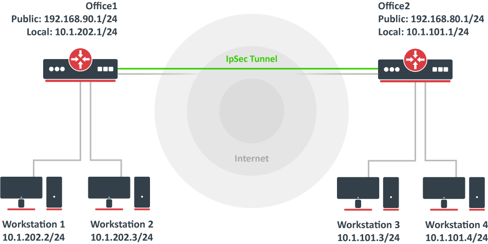
Site 1 configuration
Start off by creating a new Phase 1profileand Phase 2proposalentries using stronger or weaker encryption parameters that suit your needs. It is advised to create separate entries for each menu so that they are unique for each peer in case it is necessary to adjust any of the settings in the future. These parameters must match between the sites or else the connection will not establish.
/ip ipsec profile
add dh-group=modp2048 enc-algorithm=aes-128 name=ike1-site2
/ip ipsec proposal
add enc-algorithms=aes-128-cbc name=ike1-site2 pfs-group=modp2048
Continue by configuring a peer. Specify the address of the remote router. This address should be reachable through UDP/500 and UDP/4500 ports, so make sure appropriate actions are taken regarding the router's firewall. Specify the name for this peer as well as the newly created profile.
/ip ipsec peer
add address=192.168.80.1/32 name=ike1-site2 profile=ike1-site2
The next step is to create an identity. For a basic pre-shared key secured tunnel, there is nothing much to set except for a strong secret and the peer to which this identity applies.
/ip ipsec identity
add peer=ike1-site2 secret=thisisnotasecurepsk
If security matters, consider using IKEv2 and a different auth-method.
Lastly, create a policy that controls the networks/hosts between whom traffic should be encrypted.
/ip ipsec policy
add src-address=10.1.202.0/24 src-port=any dst-address=10.1.101.0/24 dst-port=any tunnel=yes action=encrypt proposal=ike1-site2 peer=ike1-site2
Site 2 configuration
Office 2 configuration is almost identical to Office 1 with proper IP address configuration. Start off by creating a new Phase 1 profile and Phase 2 proposal entries:
/ip ipsec profile
add dh-group=modp2048 enc-algorithm=aes-128 name=ike1-site1
/ip ipsec proposal
add enc-algorithms=aes-128-cbc name=ike1-site1 pfs-group=modp2048
Next is the peer and identity:
/ip ipsec peer
add address=192.168.90.1/32 name=ike1-site1 profile=ike1-site1
/ip ipsec identity
add peer=ike1-site1 secret=thisisnotasecurepsk
When it is done, create a policy:
/ip ipsec policy
add src-address=10.1.101.0/24 src-port=any dst-address=10.1.202.0/24 dst-port=any tunnel=yes action=encrypt proposal=ike1-site1 peer=ike1-site1
At this point, the tunnel should be established and two IPsec Security Associations should be created on both routers:
/ip ipsec
active-peers print
installed-sa print
NAT and Fasttrack Bypass
At this point if you try to send traffic over the IPsec tunnel, it will not work, packets will be lost. This is because both routers have NAT rules (masquerade) that are changing source addresses before a packet is encrypted. A router is unable to encrypt the packet because the source address does not match the address specified in the policy configuration. For more information see the IPsec packet flow example.
To fix this we need to set up IP/Firewall/NAT bypass rule.
Office 1 router:
/ip firewall nat
add chain=srcnat action=accept place-before=0 src-address=10.1.202.0/24 dst-address=10.1.101.0/24
Office 2 router:
/ip firewall nat
add chain=srcnat action=accept place-before=0 src-address=10.1.101.0/24 dst-address=10.1.202.0/24
If you previously tried to establish an IP connection before the NAT bypass rule was added, you have to clear the connection table from the existing connection or restart both routers.
It is very important that the bypass rule is placed at the top of all other NAT rules.
Another issue is if you have IP/Fasttrack enabled, the packet bypasses IPsec policies. So we need to add accept rule before FastTrack.
/ip firewall filter
add chain=forward action=accept place-before=1
src-address=10.1.101.0/24 dst-address=10.1.202.0/24 connection-state=established,related
add chain=forward action=accept place-before=1
src-address=10.1.202.0/24 dst-address=10.1.101.0/24 connection-state=established,related
However, this can add a significant load to the router's CPU if there is a fair amount of tunnels and significant traffic on each tunnel.
The solution is to use IP/Firewall/Raw to bypass connection tracking, that way eliminating the need for filter rules listed above and reducing the load on CPU by approximately 30%.
/ip firewall raw
add action=notrack chain=prerouting src-address=10.1.101.0/24 dst-address=10.1.202.0/24
add action=notrack chain=prerouting src-address=10.1.202.0/24 dst-address=10.1.101.0/24
Site to Site GRE tunnel over IPsec (IKEv2) using DNS
This example explains how it is possible to establish a secure and encrypted GRE tunnel between two RouterOS devices when one or both sites do not have a static IP address. Before making this configuration possible, it is necessary to have a DNS name assigned to one of the devices which will act as a responder (server). For simplicity, we will use RouterOS built-in DDNS service IP/Cloud.
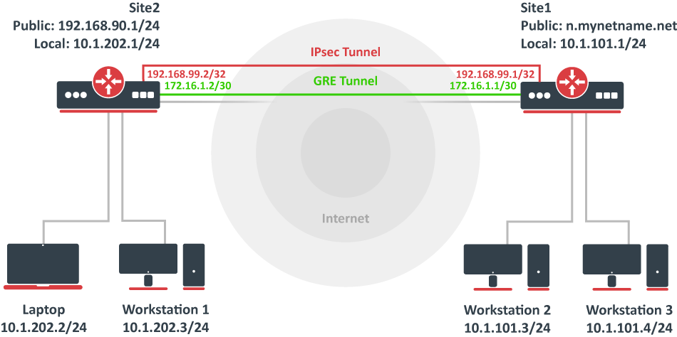
Site 1 (server) configuration
This is the side that will listen to incoming connections and act as a responder. We will use mode config to provide an IP address for the second site, but first, create a loopback (blank) bridge and assign an IP address to it that will be used later for GRE tunnel establishment.
/interface bridge
add name=loopback
/ip address
add address=192.168.99.1 interface=loopback
Continuing with the IPsec configuration, start off by creating a new Phase 1 profile and Phase 2 proposal entries using stronger or weaker encryption parameters that suit your needs. Note that this configuration example will listen to all incoming IKEv2 requests, meaning the profile configuration will be shared between all other configurations (e.g. RoadWarrior).
/ip ipsec profile
add dh-group=ecp256,modp2048,modp1024 enc-algorithm=aes-256,aes-192,aes-128 name=ike2
/ip ipsec proposal
add auth-algorithms=null enc-algorithms=aes-128-gcm name=ike2-gre pfs-group=none
Next, create a new mode config entry with responder=yes. This will provide an IP configuration for the other site as well as the host (loopback address) for policy generation.
/ip ipsec mode-config
add address=192.168.99.2 address-prefix-length=32 name=ike2-gre split-include=192.168.99.1/32 system-dns=no
It is advised to create a new policy group to separate this configuration from any existing or future IPsec configuration.
/ip ipsec policy group
add name=ike2-gre
Now it is time to set up a new policy template that will match the remote peers new dynamic address and the loopback address.
/ip ipsec policy
add dst-address=192.168.99.2/32 group=ike2-gre proposal=ike2-gre src-address=192.168.99.1/32 template=yes
The next step is to create a peer configuration that will listen to all IKEv2 requests. If you already have such an entry, you can skip this step.
/ip ipsec peer
add exchange-mode=ike2 name=ike2 passive=yes profile=ike2
Lastly, set up an identity that will match our remote peer by pre-shared-key authentication with a specific secret.
/ip ipsec identity
add generate-policy=port-strict mode-config=ike2-gre peer=ike2 policy-template-group=ike2-gre secret=test
The server side is now configured and listening to all IKEv2 requests. Please make sure the firewall is not blocking UDP/4500 port.
The last step is to create the GRE interface itself. This can also be done later when an IPsec connection is established from the client-side.
/interface gre
add local-address=192.168.99.1 name=gre-tunnel1 remote-address=192.168.99.2
Configure IP address and route to remote network through GRE interface.
/ip address
add address=172.16.1.1/30 interface=gre-tunnel1
/ip route
add dst-network=10.1.202.0/24 gateway=172.16.1.2
Site 2 (client) configuration
Similarly to server configuration, start off by creating a new Phase 1 profile and Phase 2 proposal configurations. Since this site will be the initiator, we can use a more specific profile configuration to control which exact encryption parameters are used, just make sure they overlap with what is configured on the server-side.
/ip ipsec profile
add dh-group=ecp256 enc-algorithm=aes-256 name=ike2-gre
/ip ipsec proposal
add auth-algorithms=null enc-algorithms=aes-128-gcm name=ike2-gre pfs-group=none
Next, create a new mode config entry with responder=no. This will make sure the peer requests IP and split-network configuration from the server.
/ip ipsec mode-config
add name=ike2-gre responder=no
It is also advised to create a new policy group to separate this configuration from any existing or future IPsec configuration.
/ip ipsec policy group
add name=ike2-gre
Create a new policy template on the client-side as well.
/ip ipsec policy
add dst-address=192.168.99.1/32 group=ike2-gre proposal=ike2-gre src-address=192.168.99.2/32 template=yes
Move on to peer configuration. Now we can specify the DNS name for the server under the address parameter. Obviously, you can use an IP address as well.
/ip ipsec peer
add address=n.mynetname.net exchange-mode=ike2 name=p1.ez profile=ike2-gre
Lastly, create an identity for our newly created peers.
/ip ipsec identity
add generate-policy=port-strict mode-config=ike2-gre peer=p1.ez policy-template-group=ike2-gre secret=test
If everything was done properly, there should be a new dynamic policy present.
/ip ipsec policy print
Flags: T - template, X - disabled, D - dynamic, I - invalid, A - active, * - default
0 T * group=default src-address=::/0 dst-address=::/0 protocol=all proposal=default template=yes

1 T group=ike2-gre src-address=192.168.99.2/32 dst-address=192.168.99.1/32 protocol=all proposal=ike2-gre template=yes

2 DA src-address=192.168.99.2/32 src-port=any dst-address=192.168.99.1/32 dst-port=any protocol=all action=encrypt level=unique ipsec-protocols=esp
tunnel=yes sa-src-address=192.168.90.1 sa-dst-address=(current IP of n.mynetname.net) proposal=ike2-gre ph2-count=1
A secure tunnel is now established between both sites which will encrypt all traffic between 192.168.99.2 <=> 192.168.99.1 addresses. We can use these addresses to create a GRE tunnel.
/interface gre
add local-address=192.168.99.2 name=gre-tunnel1 remote-address=192.168.99.1
Configure IP address and route to remote network through GRE interface.
/ip address
add address=172.16.1.2/30 interface=gre-tunnel1
/ip route
add dst-network=10.1.101.0/24 gateway=172.16.1.1
Road Warrior setup using IKEv2 with RSA authentication
This example explains how to establish a secure IPsec connection between a device connected to the Internet (road warrior client) and a device running RouterOS acting as a server.
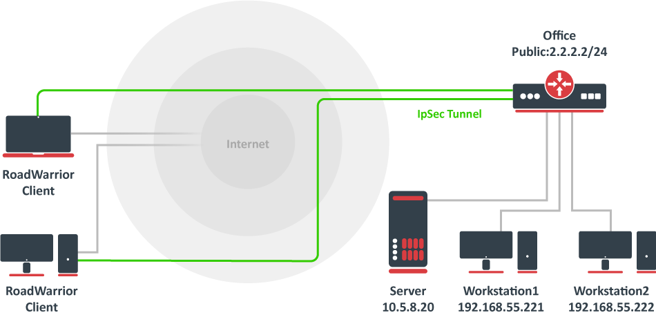
RouterOS server configuration
Before configuring IPsec, it is required to set up certificates. It is possible to use a separate Certificate Authority for certificate management, however in this example, self-signed certificates are generated in RouterOS System/Certificates menu. Some certificate requirements should be met to connect various devices to the server:
- Common name should contain IP or DNS name of the server;
- SAN (subject alternative name) should have IP or DNS of the server;
- EKU (extended key usage) tls-server and tls-client are required.
Considering all requirements above, generate CA and server certificates:
/certificate
add common-name=ca name=ca
sign ca ca-crl-host=2.2.2.2
add common-name=2.2.2.2 subject-alt-name=IP:2.2.2.2 key-usage=tls-server name=server1
sign server1 ca=ca
Now that valid certificates are created on the router, add a new Phase 1 profile and Phase 2 proposal entries with pfs-group=none:
/ip ipsec profile
add name=ike2
/ip ipsec proposal
add name=ike2 pfs-group=none
Mode config is used for address distribution from IP/Pools:
/ip pool
add name=ike2-pool ranges=192.168.77.2-192.168.77.254
/ip ipsec mode-config
add address-pool=ike2-pool address-prefix-length=32 name=ike2-conf
Since that the policy template must be adjusted to allow only specific network policies, it is advised to create a separate policy group and template.
/ip ipsec policy group
add name=ike2-policies
/ip ipsec policy
add dst-address=192.168.77.0/24 group=ike2-policies proposal=ike2 src-address=0.0.0.0/0 template=yes
Create a new IPsec peer entry that will listen to all incoming IKEv2 requests.
/ip ipsec peer
add exchange-mode=ike2 name=ike2 passive=yes profile=ike2
Identity configuration
The identity menu allows to match specific remote peers and assign different configurations for each one of them. First, create a default identity, that will accept all peers, but will verify the peer's identity with its certificate.
/ip ipsec identity
add auth-method=digital-signature certificate=server1 generate-policy=port-strict mode-config=ike2-conf peer=ike2 policy-template-group=ike2-policies
If the peer's ID (ID_i) is not matching with the certificate it sends, the identity lookup will fail. See remote-id in the identities section.
For example, we want to assign a different mode config for user "A", who uses certificate "rw-client1" to authenticate itself to the server. First of all, make sure a new mode config is created and ready to be applied for the specific user.
/ip ipsec mode-config
add address=192.168.66.2 address-prefix-length=32 name=usr_A split-include=192.168.55.0/24 system-dns=no
It is possible to apply this configuration for user "A" by using the match-by=certificate parameter and specifying his certificate with remote-certificate.
/ip ipsec identity
add auth-method=digital-signature certificate=server1 generate-policy=port-strict match-by=certificate mode-config=usr_A peer=ike2 policy-template-group=ike2-policies remote-certificate=rw-client1
(Optional) Split tunnel configuration
Split tunneling is a method that allows road warrior clients to only access a specific secured network and at the same time send the rest of the traffic based on their internal routing table (as opposed to sending all traffic over the tunnel). To configure split tunneling, changes to mode config parameters are needed.
For example, we will allow our road warrior clients to only access the 10.5.8.0/24 network.
/ip ipsec mode-conf
set [find name="rw-conf"] split-include=10.5.8.0/24
It is also possible to send a specific DNS server for the client to use. By default, system-dns=yes is used, which sends DNS servers that are configured on the router itself in IP/DNS. We can force the client to use a different DNS server by using the static-dns parameter.
/ip ipsec mode-conf
set [find name="rw-conf"] system-dns=no static-dns=10.5.8.1
While it is possible to adjust the IPsec policy template to only allow road warrior clients to generate policies to network configured by split-include parameter, this can cause compatibility issues with different vendor implementations (see known limitations). Instead of adjusting the policy template, allow access to a secured network in IP/Firewall/Filter and drop everything else.
/ip firewall filter
add action=drop chain=forward src-address=192.168.77.0/24 dst-address=!10.5.8.0/24
Split networking is not a security measure. The client (initiator) can still request a different Phase 2 traffic selector.
Generating client certificates
To generate a new certificate for the client and sign it with a previously created CA.
/certificate
add common-name=rw-client1 name=rw-client1 key-usage=tls-client
sign rw-client1 ca=ca
PKCS12 format is accepted by most client implementations, so when exporting the certificate, make sure PKCS12 is specified.
/certificate
export-certificate rw-client1 export-passphrase=1234567890 type=pkcs12
A file named cert_export_rw-client1.p12 is now located in the routers System/File section. This file should be securely transported to the client's device.
Typically PKCS12 bundle contains also a CA certificate, but some vendors may not install this CA, so a self-signed CA certificate must be exported separately using PEM format.
/certificate
export-certificate ca type=pem
A file named cert_export_ca.crt is now located in the routers System/File section. This file should also be securely transported to the client's device.
PEM is another certificate format for use in client software that does not support PKCS12. The principle is pretty much the same.
/certificate
export-certificate ca
export-certificate rw-client1 export-passphrase=1234567890
Three files are now located in the routers Files section: cert_export_ca.crt, cert_export_rw-client1.crt and cert_export_rw-client1.key which should be securely transported to the client device.
Known limitations
Here is a list of known limitations by popular client software IKEv2 implementations.
- Windows will always ignore networks received by split-include and request policy with destination 0.0.0.0/0 (TSr). When IPsec-SA is generated, Windows requests DHCP option 249 to which RouterOS will respond with configured split-include networks automatically.
- Both Apple macOS and iOS will only accept the first split-include network.
- Both Apple macOS and iOS will use the DNS servers from system-dns and static-dns parameters only when 0.0.0.0/0 split-include is used.
- While some implementations can make use of different PFS group for phase 2, it is advised to use pfs-group=none under proposals to avoid any compatibility issues.
RouterOS client configuration
Import a PKCS12 format certificate in RouterOS.
/certificate import file-name=cert_export_RouterOS_client.p12 passphrase=1234567890
There should now be the self-signed CA certificate and the client certificate in the Certificate menu. Find out the name of the client certificate.
/certificate print
cert_export_RouterOS_client.p12_0 is the client certificate.
It is advised to create a separate Phase 1 profile and Phase 2 proposal configurations to not interfere with any existing IPsec configuration.
/ip ipsec profile
add name=ike2-rw
/ip ipsec proposal
add name=ike2-rw pfs-group=none
While it is possible to use the default policy template for policy generation, it is better to create a new policy group and template to separate this configuration from any other IPsec configuration.
/ip ipsec policy group
add name=ike2-rw
/ip ipsec policy
add group=ike2-rw proposal=ike2-rw template=yes
Create a new mode config entry with responder=no that will request configuration parameters from the server.
/ip ipsec mode-config
add name=ike2-rw responder=no
Lastly, create peer and identity configurations.
/ip ipsec peer
add address=2.2.2.2/32 exchange-mode=ike2 name=ike2-rw-client
/ip ipsec identity
add auth-method=digital-signature certificate=cert_export_RouterOS_client.p12_0 generate-policy=port-strict mode-config=ike2-rw peer=ike2-rw-client policy-template-group=ike2-rw
Verify that the connection is successfully established.
/ip ipsec
active-peers print
installed-sa print
Enabling dynamic source NAT rule generation
If we look at the generated dynamic policies, we see that only traffic with a specific (received by mode config) source address will be sent through the tunnel. But a router in most cases will need to route a specific device or network through the tunnel. In such case, we can use source NAT to change the source address of packets to match the mode config address. Since the mode config address is dynamic, it is impossible to create a static source NAT rule. In RouterOS, it is possible to generate dynamic source NAT rules for mode config clients.
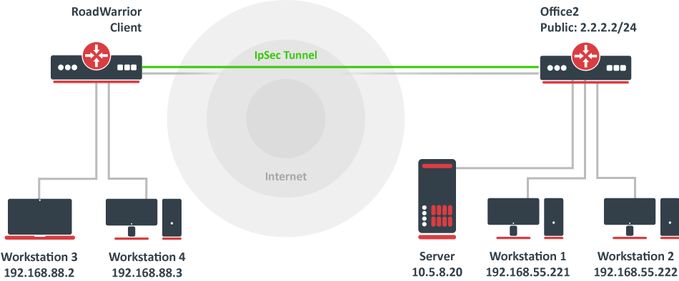
For example, we have a local network 192.168.88.0/24 behind the router and we want all traffic from this network to be sent over the tunnel. First of all, we have to make a new IP/Firewall/Address list which consists of our local network
/ip firewall address-list
add address=192.168.88.0/24 list=local
When it is done, we can assign the newly created IP/Firewall/Address list to the mode config configuration.
/ip ipsec mode-config
set [ find name=ike2-rw ] src-address-list=local
Verify correct source NAT rule is dynamically generated when the tunnel is established.
[admin@MikroTik] > /ip firewall nat print
Flags: X - disabled, I - invalid, D - dynamic
0 D ;;; ipsec mode-config
chain=srcnat action=src-nat to-addresses=192.168.77.254 src-address-list=local dst-address-list=!local
Make sure the dynamic mode config address is not a part of a local network.
Windows client configuration
Open PKCS12 format certificate file on the Windows computer. Install the certificate by following the instructions. Make sure you select the Local Machine store location.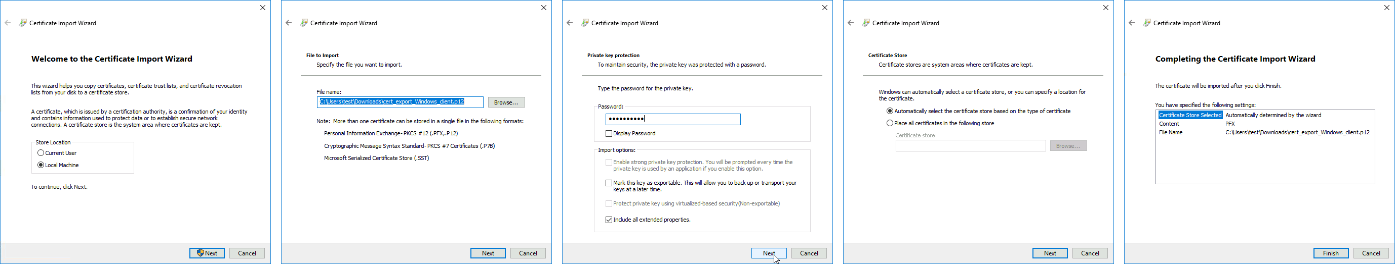 You can now proceed to Network and Internet settings -> VPN and add a new configuration. Fill in the Connection name, Server name, or address parameters. Select IKEv2 under VPN type. When it is done, it is necessary to select "Use machine certificates". This can be done in Network and Sharing Center by clicking the Properties menu for the VPN connection. The setting is located under the Security tab.
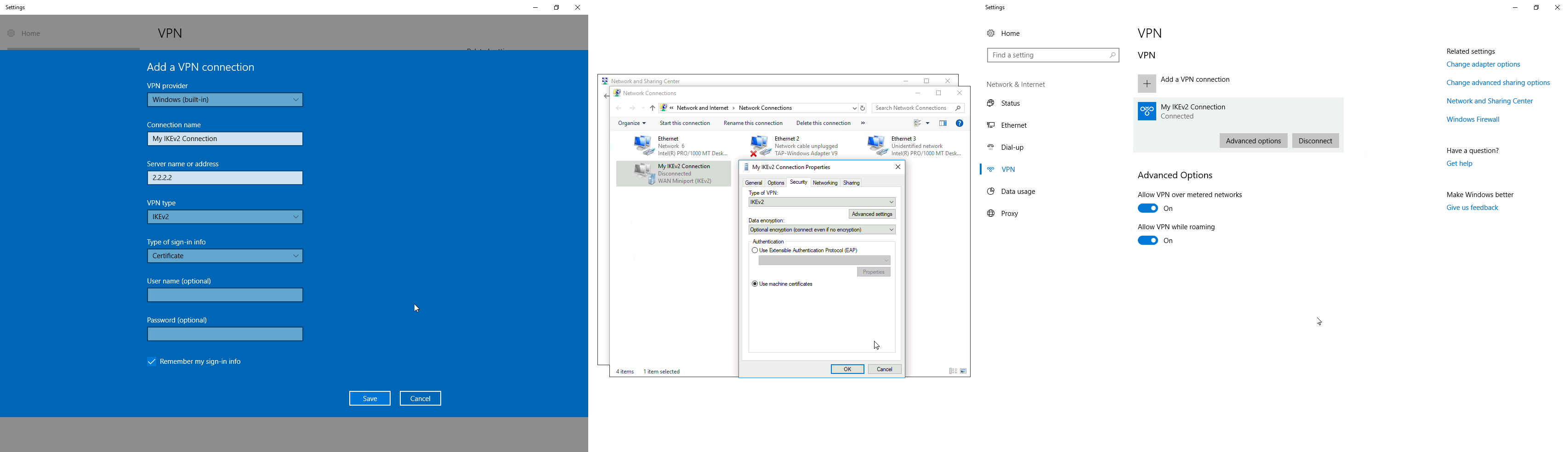
Currently, Windows 10 is compatible with the following Phase 1 ( profiles) and Phase 2 ( proposals) proposal sets:
| Phase 1 | ||
|---|---|---|
| Hash Algorithm | Encryption Algorithm | DH Group |
| SHA1 | 3DES | modp1024 |
| SHA256 | 3DES | modp1024 |
| SHA1 | AES-128-CBC | modp1024 |
| SHA256 | AES-128-CBC | modp1024 |
| SHA1 | AES-192-CBC | modp1024 |
| SHA256 | AES-192-CBC | modp1024 |
| SHA1 | AES-256-CBC | modp1024 |
| SHA256 | AES-256-CBC | modp1024 |
| SHA1 | AES-128-GCM | modp1024 |
| SHA256 | AES-128-GCM | modp1024 |
| SHA1 | AES-256-GCM | modp1024 |
| SHA256 | AES-256-GCM | modp1024 |
| Phase 2 | ||
|---|---|---|
| Hash Algorithm | Encryption Algorithm | PFS Group |
| SHA1 | AES-256-CBC | none |
| SHA1 | AES-128-CBC | none |
| SHA1 | 3DES | none |
| SHA1 | DES | none |
| SHA1 | none | none |
macOS client configuration
Open the PKCS12 format certificate file on the macOS computer and install the certificate in the "System" keychain. It is necessary to mark the CA certificate as trusted manually since it is self-signed. Locate the certificate macOS Keychain Access app under the System tab and mark it as Always Trust.

You can now proceed to System Preferences -> Network and add a new configuration by clicking the + button. Select Interface: VPN, VPN Type: IKEv2 and name your connection. Remote ID must be set equal to common-name or subjAltName of server's certificate. Local ID can be left blank. Under Authentication Settings select None and choose the client certificate. You can now test the connectivity.
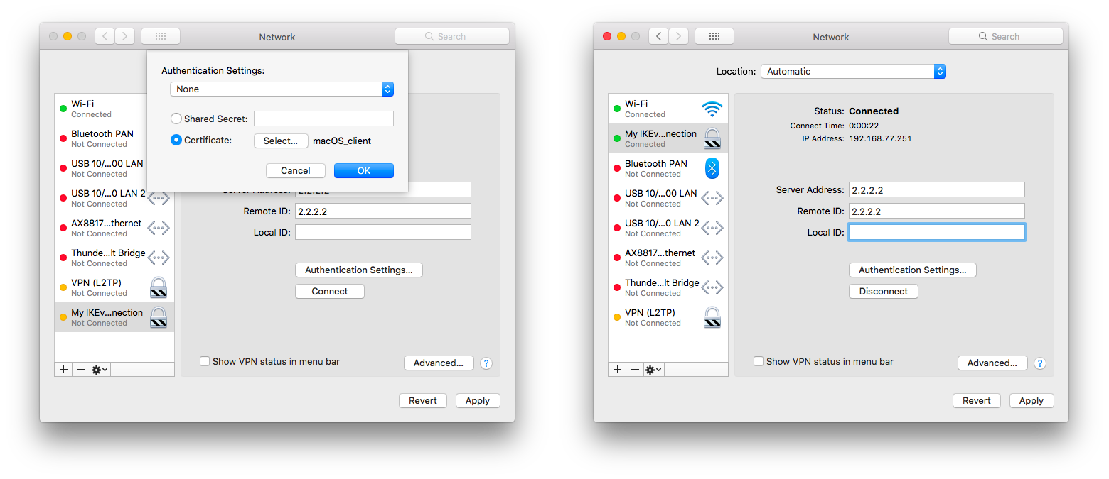
Currently, macOS is compatible with the following Phase 1 ( profiles) and Phase 2 ( proposals) proposal sets:
| Phase 1 | ||
|---|---|---|
| Hash Algorithm | Encryption Algorithm | DH Group |
| SHA256 | AES-256-CBC | modp2048 |
| SHA256 | AES-256-CBC | ecp256 |
| SHA256 | AES-256-CBC | modp1536 |
| SHA1 | AES-128-CBC | modp1024 |
| SHA1 | 3DES | modp1024 |
| Phase 2 | ||
|---|---|---|
| Hash Algorithm | Encryption Algorithm | PFS Group |
| SHA256 | AES-256-CBC | none |
| SHA1 | AES-128-CBC | none |
| SHA1 | 3DES | none |
iOS client configuration
Typically PKCS12 bundle contains also a CA certificate, but iOS does not install this CA, so a self-signed CA certificate must be installed separately using PEM format. Open these files on the iOS device and install both certificates by following the instructions. It is necessary to mark the self-signed CA certificate as trusted on the iOS device. This can be done in Settings -> General -> About -> Certificate Trust Settings menu. When it is done, check whether both certificates are marked as "verified" under the Settings -> General -> Profiles menu.
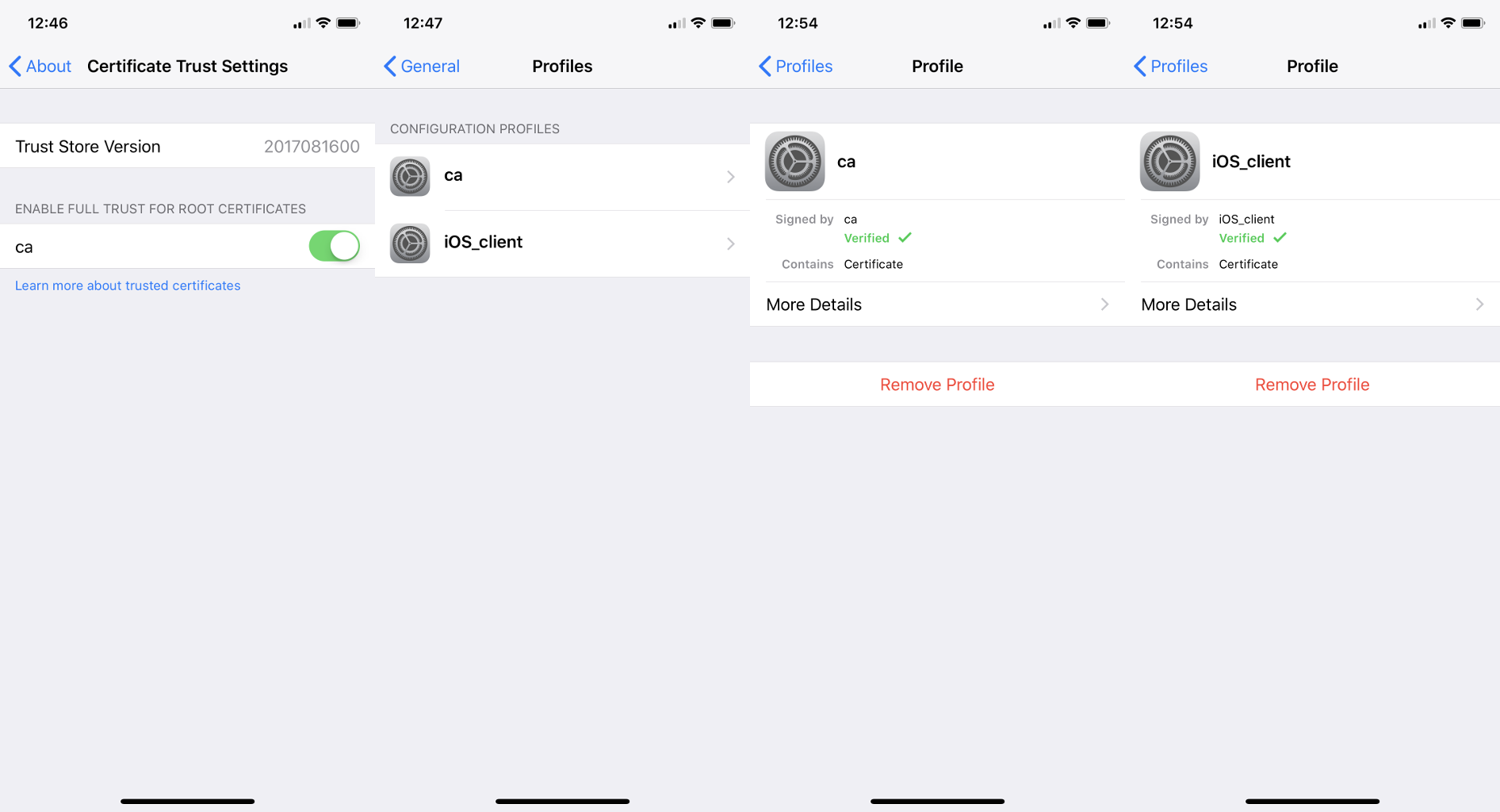
You can now proceed to Settings -> General -> VPN menu and add a new configuration. Remote ID must be set equal to common-name or subjAltName of server's certificate. Local ID can be left blank.
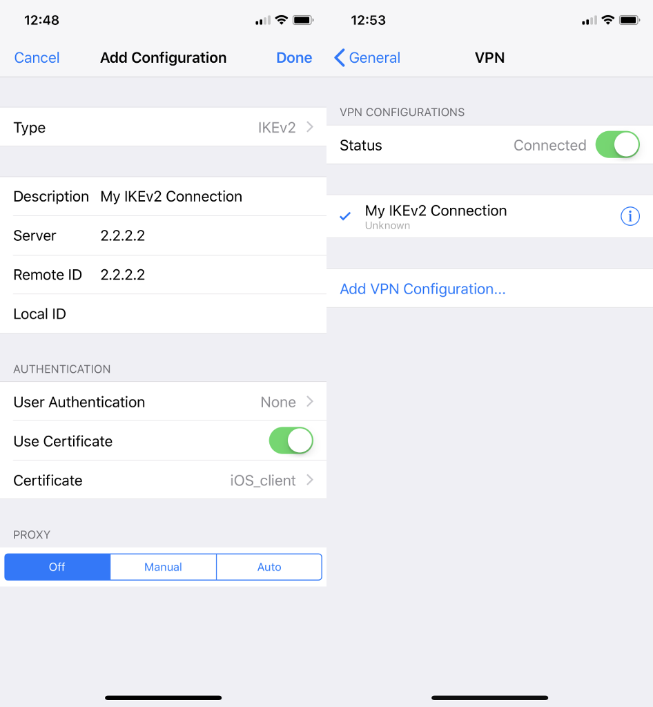
Currently, iOS is compatible with the following Phase 1 ( profiles) and Phase 2 ( proposals) proposal sets:
| Phase 1 | ||
|---|---|---|
| Hash Algorithm | Encryption Algorithm | DH Group |
| SHA256 | AES-256-CBC | modp2048 |
| SHA256 | AES-256-CBC | ecp256 |
| SHA256 | AES-256-CBC | modp1536 |
| SHA1 | AES-128-CBC | modp1024 |
| SHA1 | 3DES | modp1024 |
| Phase 2 | ||
|---|---|---|
| Hash Algorithm | Encryption Algorithm | PFS Group |
| SHA256 | AES-256-CBC | none |
| SHA1 | AES-128-CBC | none |
| SHA1 | 3DES | none |
If you are connected to the VPN over WiFi, the iOS device can go into sleep mode and disconnect from the network.
Android (strongSwan) client configuration
Currently, there is no IKEv2 native support in Android, however, it is possible to use strongSwan from Google Play Store which brings IKEv2 to Android. StrongSwan accepts PKCS12 format certificates, so before setting up the VPN connection in strongSwan, make sure you download the PKCS12 bundle to your Android device. When it is done, create a new VPN profile in strongSwan, type in the server IP, and choose "IKEv2 Certificate" as VPN Type. When selecting a User certificate, press Install and follow the certificate extract procedure by specifying the PKCS12 bundle. Save the profile and test the connection by pressing on the VPN profile.
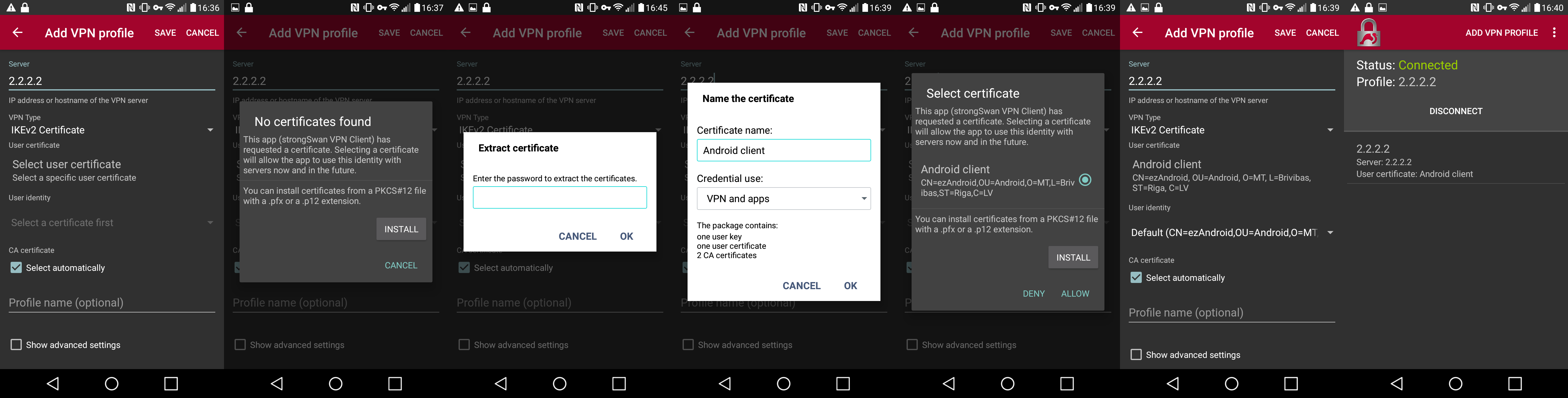
It is possible to specify custom encryption settings in strongSwan by ticking the "Show advanced settings" checkbox. Currently, strongSwan by default is compatible with the following Phase 1 ( profiles) and Phase 2 ( proposals) proposal sets:
| Phase 1 | ||
|---|---|---|
| Hash Algorithm | Encryption Algorithm | DH Group |
| SHA* | AES-*-CBC | modp2048 |
| SHA* | AES-*-CBC | ecp256 |
| SHA* | AES-*-CBC | ecp384 |
| SHA* | AES-*-CBC | ecp521 |
| SHA* | AES-*-CBC | modp3072 |
| SHA* | AES-*-CBC | modp4096 |
| SHA* | AES-*-CBC | modp6144 |
| SHA* | AES-*-CBC | modp8192 |
| SHA* | AES-*-GCM | modp2048 |
| SHA* | AES-*-GCM | ecp256 |
| SHA* | AES-*-GCM | ecp384 |
| SHA* | AES-*-GCM | ecp521 |
| SHA* | AES-*-GCM | modp3072 |
| SHA* | AES-*-GCM | modp4096 |
| SHA* | AES-*-GCM | modp6144 |
| SHA* | AES-*-GCM | modp8192 |
| Phase 2 | ||
|---|---|---|
| Hash Algorithm | Encryption Algorithm | PFS Group |
| none | AES-256-GCM | none |
| none | AES-128-GCM | none |
| SHA256 | AES-256-CBC | none |
| SHA512 | AES-256-CBC | none |
| SHA1 | AES-256-CBC | none |
| SHA256 | AES-192-CBC | none |
| SHA512 | AES-192-CBC | none |
| SHA1 | AES-192-CBC | none |
| SHA256 | AES-128-CBC | none |
| SHA512 | AES-128-CBC | none |
| SHA1 | AES-128-CBC | none |
Linux (strongSwan) client configuration
Download the PKCS12 certificate bundle and move it to /etc/ipsec.d/private directory.
Add exported passphrase for the private key to /etc/ipsec.secrets file where "strongSwan_client.p12" is the file name and "1234567890" is the passphrase.
: P12 strongSwan_client.p12 "1234567890"
Add a new connection to /etc/ipsec.conf file
conn "ikev2"
keyexchange=ikev2
ike=aes128-sha1-modp2048
esp=aes128-sha1
leftsourceip=%modeconfig
leftcert=strongSwan_client.p12
leftfirewall=yes
right=2.2.2.2
rightid="CN=2.2.2.2"
rightsubnet=0.0.0.0/0
auto=add
You can now restart (or start) the ipsec daemon and initialize the connection
$ ipsec restart
$ ipsec up ikev2
Road Warrior setup using IKEv2 with EAP-MSCHAPv2 authentication handled by User Manager (RouterOS v7)
This example explains how to establish a secure IPsec connection between a device connected to the Internet (road warrior client) and a device running RouterOS acting as an IKEv2 server and User Manager. It is possible to run User Manager on a separate device in network, however in this example both User Manager and IKEv2 server will be configured on the same device (Office).
RouterOS server configuration
Requirements
For this setup to work there are several prerequisites for the router:
- Router's IP address should have a valid public DNS record - IP Cloud could be used to achieve this.
- Router should be reachable through port TCP/80 over the Internet - if the server is behind NAT, port forwarding should be configured.
- User Manager package should be installed on the router.
Generating Let's Encrypt certificate
During the EAP-MSCHAPv2 authentication, TLS handshake has to take place, which means the server has to have a certificate that can be validated by the client. To simplify this step, we will use Let's Encrypt certificate which can be validated by most operating systems without any intervention by the user. To generate the certificate, simply enable SSL certificate under the Certificates menu. By default the command uses the dynamic DNS record provided by IP Cloud, however a custom DNS name can also be specified. Note that, the DNS record should point to the router.
/certificate enable-ssl-certificate
If the certificate generation succeeded, you should see the Let's Encrypt certificate installed under the Certificates menu.
/certificate print detail where name~"letsencrypt"
Configuring User Manager
First of all, allow receiving RADIUS requests from the localhost (the router itself):
/user-manager router
add address=127.0.0.1 comment=localhost name=local shared-secret=test
Enable the User Manager and specify the Let's Encrypt certificate (replace the name of the certificate to the one installed on your device) that will be used to authenticate the users.
/user-manager
set certificate="letsencrypt_2021-04-09T07:10:55Z" enabled=yes
Lastly add users and their credentials that clients will use to authenticate to the server.
/user-manager user
add name=user1 password=password
Configuring RADIUS client
For the router to use RADIUS server for user authentication, it is required to add a new RADIUS client that has the same shared secret that we already configured on User Manager.
/radius
add address=127.0.0.1 secret=test service=ipsec
IPsec (IKEv2) server configuration
Add a new Phase 1 profile and Phase 2 proposal entries with pfs-group=none:
/ip ipsec profile
add name=ike2
/ip ipsec proposal
add name=ike2 pfs-group=none
Mode config is used for address distribution from IP/Pools.
/ip pool
add name=ike2-pool ranges=192.168.77.2-192.168.77.254
/ip ipsec mode-config
add address-pool=ike2-pool address-prefix-length=32 name=ike2-conf
Since that the policy template must be adjusted to allow only specific network policies, it is advised to create a separate policy group and template.
/ip ipsec policy group
add name=ike2-policies
/ip ipsec policy
add dst-address=192.168.77.0/24 group=ike2-policies proposal=ike2 src-address=0.0.0.0/0 template=yes
Create a new IPsec peer entry which will listen to all incoming IKEv2 requests.
/ip ipsec peer
add exchange-mode=ike2 name=ike2 passive=yes profile=ike2
Lastly create a new IPsec identity entry that will match all clients trying to authenticate with EAP. Note that generated Let's Encrypt certificate must be specified.
/ip ipsec identity
add auth-method=eap-radius certificate="letsencrypt_2021-04-09T07:10:55Z" generate-policy=port-strict mode-config=ike2-conf peer=ike2 \
policy-template-group=ike2-policies
(Optional) Split tunnel configuration
Split tunneling is a method that allows road warrior clients to only access a specific secured network and at the same time send the rest of the traffic based on their internal routing table (as opposed to sending all traffic over the tunnel). To configure split tunneling, changes to mode config parameters are needed.
For example, we will allow our road warrior clients to only access the 10.5.8.0/24 network.
/ip ipsec mode-conf
set [find name="rw-conf"] split-include=10.5.8.0/24
It is also possible to send a specific DNS server for the client to use. By default, system-dns=yes is used, which sends DNS servers that are configured on the router itself in IP/DNS. We can force the client to use a different DNS server by using the static-dns parameter.
/ip ipsec mode-conf
set [find name="rw-conf"] system-dns=no static-dns=10.5.8.1
Split networking is not a security measure. The client (initiator) can still request a different Phase 2 traffic selector.
(Optional) Assigning static IP address to user
Static IP address to any user can be assigned by use of RADIUS Framed-IP-Address attribute.
/user-manager user
set [find name="user1"] attributes=Framed-IP-Address:192.168.77.100 shared-users=1
To avoid any conflicts, the static IP address should be excluded from the IP pool of other users, as well as shared-users should be set to 1 for the specific user.
(Optional) Accounting configuration
To keep track of every user's uptime, download and upload statistics, RADIUS accounting can be used. By default RADIUS accounting is already enabled for IPsec, but it is advised to configure Interim Update timer that sends statistic to the RADIUS server regularly. If the router will handle a lot of simultaneous sessions, it is advised to increase the update timer to avoid increased CPU usage.
/ip ipsec settings
set interim-update=1m
Basic L2TP/IPsec setup
This example demonstrates how to easily set up an L2TP/IPsec server on RouterOS for road warrior connections (works with Windows, Android, iOS, macOS, and other vendor L2TP/IPsec implementations).
RouterOS server configuration
The first step is to enable the L2TP server:
/interface l2tp-server server
set enabled=yes use-ipsec=required ipsec-secret=mySecret default-profile=default
use-ipsec is set to required to make sure that only IPsec encapsulated L2TP connections are accepted.
Now what it does is enables an L2TP server and creates a dynamic IPsec peer with a specified secret.
[admin@MikroTik] /ip ipsec peer> print
0 D address=0.0.0.0/0 local-address=0.0.0.0 passive=yes port=500
auth-method=pre-shared-key secret="123" generate-policy=port-strict
exchange-mode=main-l2tp send-initial-contact=yes nat-traversal=yes
hash-algorithm=sha1 enc-algorithm=3des,aes-128,aes-192,aes-256
dh-group=modp1024 lifetime=1d dpd-interval=2m dpd-maximum-failures=5
Care must be taken if static IPsec peer configuration exists.
The next step is to create a VPN pool and add some users.
/ip pool add name=vpn-pool range=192.168.99.2-192.168.99.100

/ppp profile
set default local-address=192.168.99.1 remote-address=vpn-pool

/ppp secret
add name=user1 password=123
add name=user2 password=234
Now the router is ready to accept L2TP/IPsec client connections.
RouterOS client configuration
For RouterOS to work as L2TP/IPsec client, it is as simple as adding a new L2TP client.
/interface l2tp-client
add connect-to=1.1.1.1 disabled=no ipsec-secret=mySecret name=l2tp-out1 \
password=123 use-ipsec=yes user=user1
It will automatically create dynamic IPsec peer and policy configurations.
Troubleshooting/FAQ
Phase 1 Failed to get a valid proposal
[admin@MikroTik] /log> print
(..)
17:12:32 ipsec,error no suitable proposal found.
17:12:32 ipsec,error 10.5.107.112 failed to get valid proposal.
17:12:32 ipsec,error 10.5.107.112 failed to pre-process ph1 packet (side: 1, status 1).
17:12:32 ipsec,error 10.5.107.112 phase1 negotiation failed.
(..)
Peers are unable to negotiate encryption parameters causing the connection to drop. To solve this issue, enable IPSec to debug logs and find out which parameters are proposed by the remote peer, and adjust the configuration accordingly.
[admin@MikroTik] /system logging> add topics=ipsec,!debug
[admin@MikroTik] /log> print
(..)
17:21:08 ipsec rejected hashtype: DB(prop#1:trns#1):Peer(prop#1:trns#1) = MD5:SHA
17:21:08 ipsec rejected enctype: DB(prop#1:trns#2):Peer(prop#1:trns#1) = 3DES-CBC:AES-CBC
17:21:08 ipsec rejected hashtype: DB(prop#1:trns#2):Peer(prop#1:trns#1) = MD5:SHA
17:21:08 ipsec rejected enctype: DB(prop#1:trns#1):Peer(prop#1:trns#2) = AES-CBC:3DES-CBC
17:21:08 ipsec rejected hashtype: DB(prop#1:trns#1):Peer(prop#1:trns#2) = MD5:SHA
17:21:08 ipsec rejected hashtype: DB(prop#1:trns#2):Peer(prop#1:trns#2) = MD5:SHA
17:21:08 ipsec,error no suitable proposal found.
17:21:08 ipsec,error 10.5.107.112 failed to get valid proposal.
17:21:08 ipsec,error 10.5.107.112 failed to pre-process ph1 packet (side: 1, status 1).
17:21:08 ipsec,error 10.5.107.112 phase1 negotiation failed.
(..)
In this example, the remote end requires SHA1 to be used as a hash algorithm, but MD5 is configured on the local router. Setting before the column symbol (:) is configured on the local side, parameter after the column symbol (:) is configured on the remote side.
"phase1 negotiation failed due to time up" what does it mean?
There are communication problems between the peers. Possible causes include - misconfigured Phase 1 IP addresses; firewall blocking UDP ports 500 and 4500; NAT between peers not properly translating IPsec negotiation packets. This error message can also appear when a local-address parameter is not used properly. More information available here.
Random packet drops or connections over the tunnel are very slow, enabling packet sniffer/torch fixes the problem?
Problem is that before encapsulation packets are sent to Fasttrack/FastPath, thus bypassing IPsec policy checking. The solution is to exclude traffic that needs to be encapsulated/decapsulated from Fasttrack, see configuration example here.
How to enable ike2?
For basic configuration enabling ike2 is very simple, just change exchange-mode in peer settings to ike2.
fatal NO-PROPOSAL-CHOSEN notify message?
Remote peer sent notify that it cannot accept proposed algorithms, to find the exact cause of the problem, look at remote peers debug logs or configuration and verify that both client and server have the same set of algorithms.
I can ping only in one direction?
A typical problem in such cases is strict firewall, firewall rules allow the creation of new connections only in one direction. The solution is to recheck firewall rules, or explicitly accept all traffic that should be encapsulated/decapsulated.
Can I allow only encrypted traffic?
Yes, you can, see "Allow only IPsec encapsulated traffic" examples.
I enable IKEv2 REAUTH on StrongSwan and got the error 'initiator did not reauthenticate as requested'
RouterOS does not support rfc4478, reauth must be disabled on StrongSwan.
Page edited by Edgars P.
- Summary
- Bridge Interface Setup
- Spanning Tree Protocol
- Bridge Settings
- Port Settings
- Hosts Table
- Multicast Table
- Bridge Hardware Offloading
- Bridge VLAN Filtering
- Fast Forward
- IGMP/MLD Snooping
- DHCP Snooping and DHCP Option 82
- Controller Bridge and Port Extender
- Bridge Firewall
- See also
Summary
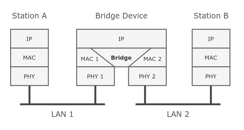
Ethernet-like networks (Ethernet, Ethernet over IP, IEEE 802.11 in ap-bridge or bridge mode, WDS, VLAN) can be connected together using MAC bridges. The bridge feature allows the interconnection of hosts connected to separate LANs (using EoIP, geographically distributed networks can be bridged as well if any kind of IP network interconnection exists between them) as if they were attached to a single LAN. As bridges are transparent, they do not appear in the traceroute list, and no utility can make a distinction between a host working in one LAN and a host working in another LAN if these LANs are bridged. However, depending on the way the LANs are interconnected, latency and data rate between hosts may vary.
Network loops may emerge (intentionally or not) in complex topologies. Without any special treatment, loops would prevent the network from functioning normally, as they would lead to avalanche-like packet multiplication. Each bridge runs an algorithm that calculates how the loop can be prevented. (R/M)STP allows bridges to communicate with each other, so they can negotiate a loop-free topology. All other alternative connections that would otherwise form loops are put on standby, so that should the main connection fail, another connection could take its place. This algorithm exchanges configuration messages (BPDU - Bridge Protocol Data Unit) periodically, so that all bridges are updated with the newest information about changes in a network topology. (R/M)STP selects a root bridge which is responsible for network reconfiguration, such as blocking and opening ports on other bridges. The root bridge is the bridge with the lowest bridge ID.
Bridge Interface Setup
To combine a number of networks into one bridge, a bridge interface should be created. Later, all the desired interfaces should be set up as its ports. One MAC address from slave (secondary) ports will be assigned to the bridge interface. The MAC address will be chosen automatically, depending on the "port-number", and it can change after a reboot. To avoid unwanted MAC address changes, it is recommended to disable "auto-mac" and manually specifying the MAC address by using "admin-mac".
Sub-menu: /interface bridge
| Property | Description | |||||||||||||||||||||||||||
|---|---|---|---|---|---|---|---|---|---|---|---|---|---|---|---|---|---|---|---|---|---|---|---|---|---|---|---|---|
| add-dhcp-option82 (yes | no; Default: no) | Whether to add DHCP Option-82 information (Agent Remote ID and Agent Circuit ID) to DHCP packets. Can be used together with Option-82 capable DHCP server to assign IP addresses and implement policies. This property only has an effect when dhcp-snooping is set to yes. | |||||||||||||||||||||||||||
| admin-mac (MAC address; Default: none) | Static MAC address of the bridge. This property only has an effect when auto-mac is set to no. | |||||||||||||||||||||||||||
| ageing-time (time; Default: 00:05:00) | How long a host's information will be kept in the bridge database. | |||||||||||||||||||||||||||
| arp (disabled | enabled | local-proxy-arp | proxy-arp | reply-only; Default: enabled) | Address Resolution Protocol setting
| |||||||||||||||||||||||||||
| arp-timeout (auto | integer; Default: auto) | How long the ARP record is kept in the ARP table after no packets are received from IP address. Value auto equals to the value of arp-timeout in ip/settings, default is 30s. | |||||||||||||||||||||||||||
| auto-mac (yes | no; Default: yes) | Automatically select one MAC address of bridge ports as a bridge MAC address, bridge MAC will be chosen from the first added bridge port. After a device reboots, the bridge MAC can change depending on the port-number. | |||||||||||||||||||||||||||
| comment (string; Default: ) | Short description of the interface. | |||||||||||||||||||||||||||
| dhcp-snooping (yes | no; Default: no) | Enables or disables DHCP Snooping on the bridge. | |||||||||||||||||||||||||||
| disabled (yes | no; Default: no) | Changes whether the bridge is disabled. | |||||||||||||||||||||||||||
| ether-type (0x9100 | 0x8100 | 0x88a8; Default: 0x8100) | Changes the EtherType, which will be used to determine if a packet has a VLAN tag. Packets that have a matching EtherType are considered as tagged packets. This property only has an effect when vlan-filtering is set to yes. | |||||||||||||||||||||||||||
| fast-forward (yes | no; Default: yes) | Special and faster case of Fast Path which works only on bridges with 2 interfaces (enabled by default only for new bridges). More details can be found in the Fast Forward section. | |||||||||||||||||||||||||||
| forward-delay (time; Default: 00:00:15) | The time which is spent during the initialization phase of the bridge interface (i.e., after router startup or enabling the interface) in the listening/learning state before the bridge will start functioning normally. | |||||||||||||||||||||||||||
| forward-reserved-addresses (yes | no: Default: no) | Whether to forward IEEE reserved multicast MAC address that are in the 01:80:C2:00:00:0x range. Bridges compliant with R/M/STP standards should refrain from forwarding these packets, this property can only be applied when Enabling forwarding of reserved MAC addresses may affect certain protocols relying on these addresses. It is advisable to enable forwarding only when absolutely necessary, such as in transparent bridging setups (e.g., extending long links, using bridge as media converters, or conducting network analysis). Here are some notable MAC addresses and protocols used by RouterOS:
The Flow Control MAC address 01:80:C2:00:00:01 is an exception, it does not get forwarded by the bridge. | |||||||||||||||||||||||||||
| frame-types (admit-all | admit-only-untagged-and-priority-tagged | admit-only-vlan-tagged; Default: admit-all) | Specifies allowed frame types on a bridge port. This property only has an effect when vlan-filtering is set to yes. | |||||||||||||||||||||||||||
| igmp-snooping (yes | no; Default: no) | Enables multicast group and port learning to prevent multicast traffic from flooding all interfaces in a bridge. | |||||||||||||||||||||||||||
| igmp-version (2 | 3; Default: 2) | Selects the IGMP version in which IGMP membership queries will be generated when the bridge interface is acting as an IGMP querier. This property only has an effect when igmp-snooping and multicast-querier is set to yes. | |||||||||||||||||||||||||||
| ingress-filtering (yes | no; Default: yes) | Enables or disables VLAN ingress filtering, which checks if the ingress port is a member of the received VLAN ID in the bridge VLAN table. By default, VLANs that don't exist in the bridge VLAN table are dropped before they are sent out (egress), but this property allows you to drop the packets when they are received (ingress). Should be used with frame-types to specify if the ingress traffic should be tagged or untagged. This property only has an effect when vlan-filtering is set to yes. The setting is enabled by default since RouterOS v7. | |||||||||||||||||||||||||||
| l2mtu (read-only; Default: ) | L2MTU indicates the maximum size of the frame without a MAC header that can be sent by this interface. The L2MTU value will be automatically set by the bridge and it will use the lowest L2MTU value of any associated bridge port. This value cannot be manually changed. | |||||||||||||||||||||||||||
| last-member-interval (time; Default: 1s) | When the last client on the bridge port unsubscribes to a multicast group and the bridge is acting as an active querier, the bridge will send group-specific IGMP/MLD query, to make sure that no other client is still subscribed. The setting changes the response time for these queries. In case no membership reports are received in a certain time period ( If the bridge port is configured with fast-leave, the multicast group is removed right away without sending any queries. This property only has an effect when | |||||||||||||||||||||||||||
| last-member-query-count (integer: 0..4294967295; Default: 2) | How many times should last-member-interval pass until the IGMP/MLD snooping bridge stops forwarding a certain multicast stream. This property only has an effect when igmp-snooping and multicast-querier is set to yes. | |||||||||||||||||||||||||||
| max-hops (integer: 6..40; Default: 20) | Bridge count which BPDU can pass in an MSTP enabled network in the same region before BPDU is being ignored. This property only has an effect when protocol-mode is set to mstp. | |||||||||||||||||||||||||||
| max-learned-entries (integer: 0..4294967295 | auto | unlimited; Default: auto) | Sets the maximum number of learned hosts for the bridge interface. The default value is The default values for certain RAM sizes:
This limit specifically applies to the bridge interface, not the hardware limits on the switch FDB table. Even if the bridge limit is reached, the switch can continue learn hosts up to its hardware limits and make correct forwarding decisions. However, these additional hosts will not show up in the " This setting has been available since RouterOS version 7.16. | |||||||||||||||||||||||||||
| max-message-age (time: 6s..40s; Default: 00:00:20) | Changes the Max Age value in BPDU packets, which is transmitted by the root bridge. A root bridge sends a BPDUs with Max Age set to max-message-age value and a Message Age of 0. Every sequential bridge will increment the Message Age before sending their BPDUs. Once a bridge receives a BPDU where Message Age is equal or greater than Max Age, the BPDU is ignored. This property only has an effect when protocol-mode is set to stp or rstp. | |||||||||||||||||||||||||||
| membership-interval (time; Default: 4m20s) | The amount of time after an entry in the Multicast Database (MDB) is removed if no IGMP/MLD membership reports are received on a bridge port. This property only has an effect when igmp-snooping is set to yes. | |||||||||||||||||||||||||||
| mld-version (1 | 2; Default: 1) | Selects the MLD version in which MLD membership queries will be generated, when the bridge interface is acting as an MLD querier. This property only has an effect when the bridge has an active IPv6 address, igmp-snooping and multicast-querier is set to yes. | |||||||||||||||||||||||||||
| mtu (integer; Default: auto) | Maximum transmission unit, by default, the bridge will set MTU automatically and it will use the lowest MTU value of any associated bridge port. The default bridge MTU value without any bridge ports added is 1500. The MTU value can be set manually, but it cannot exceed the bridge L2MTU or the lowest bridge port L2MTU. If a new bridge port is added with L2MTU which is smaller than the When adding VLAN interfaces on the bridge, and when VLAN is using higher MTU than default 1500, it is recommended to set manually the MTU of the bridge. | |||||||||||||||||||||||||||
| multicast-querier (yes | no; Default: no) | Multicast querier generates periodic IGMP/MLD general membership queries to which all IGMP/MLD capable devices respond with an IGMP/MLD membership report, usually a PIM (multicast) router or IGMP proxy generates these queries. By using this property you can make an IGMP/MLD snooping enabled bridge to generate IGMP/MLD general membership queries. This property should be used whenever there is no active querier (PIM router or IGMP proxy) in a Layer2 network. Without a multicast querier in a Layer2 network, the Multicast Database (MDB) is not being updated, the learned entries will timeout and IGMP/MLD snooping will not function properly. Only untagged IGMP/MLD general membership queries are generated, IGMP queries are sent with IPv4 0.0.0.0 source address, MLD queries are sent with IPv6 link-local address of the bridge interface. The bridge will not send queries if an external IGMP/MLD querier is detected (see the monitoring values This property only has an effect when | |||||||||||||||||||||||||||
| multicast-router (disabled | permanent | temporary-query; Default: temporary-query) | A multicast router port is a port where a multicast router or querier is connected. On this port, unregistered multicast streams and IGMP/MLD membership reports will be sent. This setting changes the state of the multicast router for a bridge interface itself. This property can be used to send IGMP/MLD membership reports to the bridge interface for further multicast routing or proxying. This property only has an effect when igmp-snooping is set to yes.
| |||||||||||||||||||||||||||
| name (text; Default: bridgeN) | Name of the bridge interface. | |||||||||||||||||||||||||||
| port-cost-mode (long | short; Default: long) | Changes the port path-cost and internal-path-cost mode for bridged ports, utilizing automatic values based on interface speed. This setting does not impact bridged ports with manually configured
For bonded interfaces, the highest path-cost among all bonded member ports is applied, this value remains unaffected by the total link speed of the bonding. For virtual interfaces (such as VLAN, EoIP, VXLAN), as well as wifi, wireless, and 60GHz interfaces, a path-cost of 20,000 is assigned for long mode, and 10 for short mode. For dynamically bridged interfaces (e.g. wifi, wireless, PPP, VPLS), the path-cost defaults to 20,000 for long mode and 10 for short mode. However, this can be manually overridden by the service that dynamically adds interfaces to bridge, for instance, by using the CAPsMAN Use port monitor to observe the applied path-cost. This property has an effect when | |||||||||||||||||||||||||||
| priority (integer: 0..65535 decimal format or 0x0000-0xffff hex format; Default: 32768 / 0x8000) | Bridge priority, used by R/STP to determine root bridge, used by MSTP to determine CIST and IST regional root bridge. This property has no effect when protocol-mode is set to none. | |||||||||||||||||||||||||||
| protocol-mode (none | rstp | stp | mstp; Default: rstp) | Select Spanning tree protocol (STP) or Rapid spanning tree protocol (RSTP) to ensure a loop-free topology for any bridged LAN. RSTP provides a faster spanning tree convergence after a topology change. Select MSTP to ensure loop-free topology across multiple VLANs. The forwarding of reserved MAC addresses that are in the 01:80:C2:00:00:0x range is separated from | |||||||||||||||||||||||||||
| pvid (integer: 1..4094; Default: 1) | Port VLAN ID (pvid) specifies which VLAN the untagged ingress traffic is assigned to. It applies e.g. to frames sent from bridge IP and destined to a bridge port. This property only has an effect when vlan-filtering is set to yes. | |||||||||||||||||||||||||||
| querier-interval (time; Default: 4m15s) | Changes the timeout period for detected querier and multicast-router ports. This property only has an effect when igmp-snooping is set to yes. | |||||||||||||||||||||||||||
| query-interval (time; Default: 2m5s) | Changes the interval on how often IGMP/MLD general membership queries are sent out when the bridge interface is acting as an IGMP/MLD querier. The interval takes place when the last startup query is sent. This property only has an effect when igmp-snooping and multicast-querier is set to yes. | |||||||||||||||||||||||||||
| query-response-interval (time; Default: 10s) | The setting changes the response time for general IGMP/MLD queries when the bridge is active as an IGMP/MLD querier. This property only has an effect when igmp-snooping and multicast-querier is set to yes. | |||||||||||||||||||||||||||
| region-name (text; Default: ) | MSTP region name. This property only has an effect when protocol-mode is set to mstp. | |||||||||||||||||||||||||||
| region-revision (integer: 0..65535; Default: 0) | MSTP configuration revision number. This property only has an effect when protocol-mode is set to mstp. | |||||||||||||||||||||||||||
| startup-query-count (integer: 0..4294967295; Default: 2) | Specifies how many times general IGMP/MLD queries must be sent when bridge interface is enabled or active querier timeouts. This property only has an effect when igmp-snooping and multicast-querier is set to yes. | |||||||||||||||||||||||||||
| startup-query-interval (time; Default: 31s250ms) | Specifies the interval between startup general IGMP/MLD queries. This property only has an effect when igmp-snooping and multicast-querier is set to yes. | |||||||||||||||||||||||||||
| transmit-hold-count (integer: 1..10; Default: 6) | The Transmit Hold Count used by the Port Transmit state machine to limit the transmission rate. | |||||||||||||||||||||||||||
| vlan-filtering (yes | no; Default: no) | Globally enables or disables VLAN functionality for the bridge. |
Changing certain properties can cause the bridge to temporarily disable all ports. This must be taken into account whenever changing such properties on production environments since it can cause all packets to be temporarily dropped. Such properties include vlan-filtering, protocol-mode, igmp-snooping, fast-forward and others.
Example
To add and enable a bridge interface that will forward L2 packets:
[admin@MikroTik] > interface bridge add
[admin@MikroTik] > interface bridge print
Flags: X - disabled, R - running
0 R name="bridge1" mtu=auto actual-mtu=1500 l2mtu=65535 arp=enabled arp-timeout=auto mac-address=5E:D2:42:95:56:7F protocol-mode=rstp fast-forward=yes
igmp-snooping=no auto-mac=yes ageing-time=5m priority=0x8000 max-message-age=20s forward-delay=15s transmit-hold-count=6 vlan-filtering=no
dhcp-snooping=no
Bridge Monitoring
To monitor the current status of a bridge interface, use the monitor command.
Sub-menu: /interface bridge monitor
| Property | Description |
|---|---|
| current-mac-address (MAC address) | Current MAC address of the bridge |
| designated-port-count (integer) | Number of designated bridge ports |
| igmp-querier (none | interface & IPv4 address) | Shows a bridge port and source IP address from the detected IGMP querier. Only shows detected external IGMP querier, local bridge IGMP querier (including IGMP proxy and PIM) will not be displayed. Monitoring value appears only when igmp-snooping is enabled. |
| mld-querier (none | interface & IPv6 address) | Shows a bridge port and source IPv6 address from the detected MLD querier. Only shows detected external MLD querier, local bridge MLD querier will not be displayed. Monitoring value appears only when igmp-snooping is enabled and the bridge has an active IPv6 address. |
| multicast-router (yes | no) | Shows if a multicast router is detected on the port. Monitoring value appears only when igmp-snooping is enabled. |
| port-count (integer) | Number of the bridge ports |
| root-bridge (yes | no) | Shows whether the bridge is the root bridge of the spanning tree |
| root-bridge-id (text) | The root bridge ID, which is in form of bridge-priority.bridge-MAC-address |
| root-path-cost (integer) | The total cost of the path to the root-bridge |
| root-port (name) | Port to which the root bridge is connected to |
| state (enabled | disabled) | State of the bridge |
[admin@MikroTik] /interface bridge monitor bridge1
                  state: enabled
    current-mac-address: CC:2D:E0:E4:B3:38
            root-bridge: yes
         root-bridge-id: 0x8000.CC:2D:E0:E4:B3:38
         root-path-cost: 0
              root-port: none
             port-count: 2
  designated-port-count: 2
           fast-forward: no
Spanning Tree Protocol
RouterOS bridge interfaces are capable of running Spanning Tree Protocol to ensure a loop-free and redundant topology. For small networks with just 2 bridges STP does not bring many benefits, but for larger networks properly configured STP is very crucial, leaving STP-related values to default may result in a completely unreachable network in case of an even single bridge failure. To achieve a proper loop-free and redundant topology, it is necessary to properly set bridge priorities, port path costs, and port priorities.
In RouterOS it is possible to set any value for bridge priority between 0 and 65535, the IEEE 802.1W standard states that the bridge priority must be in steps of 4096. This can cause incompatibility issues between devices that do not support such values. To avoid compatibility issues, it is recommended to use only these priorities: 0, 4096, 8192, 12288, 16384, 20480, 24576, 28672, 32768, 36864, 40960, 45056, 49152, 53248, 57344, 61440
STP has multiple variants, currently, RouterOS supports STP, RSTP, and MSTP. Depending on needs, either one of them can be used, some devices are able to run some of these protocols using hardware offloading, detailed information about which device support it can be found in the Hardware Offloading section. STP is considered to be outdated and slow, it has been almost entirely replaced in all network topologies by RSTP, which is backward compatible with STP. For network topologies that depend on VLANs, it is recommended to use MSTP since it is a VLAN aware protocol and gives the ability to do load balancing per VLAN groups. There are a lot of considerations that should be made when designing an STP enabled network, more detailed case studies can be found in the Spanning Tree Protocol article. In RouterOS, the protocol-mode property controls the used STP variant.
RouterOS bridge does not work with PVST and its variants. The PVST BPDUs (with a MAC destination 01:00:0C:CC:CC:CD) are treated by RouterOS bridges as typical multicast packets. In simpler terms, they undergo RouterOS bridge/switch forwarding logic and may get tagged or untagged.
By the IEEE 802.1ad standard, the BPDUs from bridges that comply with IEEE 802.1Q are not compatible with IEEE 802.1ad bridges, this means that the same bridge VLAN protocol should be used across all bridges in a single Layer2 domain, otherwise (R/M)STP will not function properly.
Per-port STP
There might be certain situations where you want to limit STP functionality on single or multiple ports. Below you can find some examples for different use cases.
Be careful when changing the default (R/M)STP functionality, make sure you understand the working principles of STP and BPDUs. Misconfigured (R/M)STP can cause unexpected behavior.
Create edge ports
Setting a bridge port as an edge port will restrict it from sending BPDUs and will ignore any received BPDUs:
/interface bridge
add name=bridge1
/interface bridge port
add bridge=bridge1 interface=ether1 edge=yes
add bridge=bridge1 interface=ether2
Drop received BPDUs
The bridge filter or NAT rules cannot drop BPDUs when the bridge has STP/RSTP/MSTP enabled due to the special processing of BPDUs. However, dropping received BPDUs on a certain port can be done on some switch chips using ACL rules:
On CRS3xx:
/interface ethernet switch rule
add dst-mac-address=01:80:C2:00:00:00/FF:FF:FF:FF:FF:FF new-dst-ports="" ports=ether1 switch=switch1
On CRS1xx/CRS2xx with Access Control List (ACL) support:
/interface ethernet switch acl
add action=drop mac-dst-address=01:80:C2:00:00:00 src-ports=ether1
In this example all received BPDUs on ether1 are dropped.
If you intend to drop received BPDUs on a port, then make sure to prevent BPDUs from being sent out from the interface that this port is connected to. A root bridge always sends out BPDUs and under normal conditions is waiting for a more superior BPDU (from a bridge with a lower bridge ID), but the bridge must temporarily disable the new root-port when transitioning from a root bridge to a designated bridge. If you have blocked BPDUs only on one side, then a port will flap continuously.
Enable BPDU guard
In this example, if ether1 receives a BPDU, it will block the port and will require you to manually re-enable it.
/interface bridge
add name=bridge1
/interface bridge port
add bridge=bridge1 interface=ether1 bpdu-guard=yes
add bridge=bridge1 interface=ether2
Enable Root guard
In this example, ether1 is configured with restricted-role=yes. It prevented the port from becoming the root port for the CIST or any MSTI, regardless of its best spanning tree priority vector. Such a port will be selected as an Alternate Port (discarding state) and remains so as long as it continues to receive superior BPDUs. It will automatically transition to the forwarding state when it no longer detects a superior root path. Network administrators may enable this setting to safeguard against external bridges influencing the active spanning tree.
/interface bridge
add name=bridge1
/interface bridge port
add bridge=bridge1 interface=ether1 restricted-role=yes
add bridge=bridge1 interface=ether2

[admin@MikroTik] /interface/bridge/port monitor [find]
                 interface: ether1                   ether2
                    status: in-bridge                in-bridge
               port-number: 1                        2
                      role: alternate-port           designated-port
                 edge-port: no                       yes
       edge-port-discovery: yes                      yes
       point-to-point-port: yes                      yes
              external-fdb: no                       no
              sending-rstp: yes                      yes
                  learning: no                       yes
                forwarding: no                       yes
          actual-path-cost: 20000                    20000
            root-path-cost: 20000
         designated-bridge: 0x7000.64:D1:54:C7:3A:6E
           designated-cost: 0
    designated-port-number: 1
          hw-offload-group: switch1                  switch1
Bridge Settings
Under the bridge settings menu, it is possible to control certain features for all bridge interfaces and monitor global bridge counters.
Sub-menu: /interface bridge settings
| Property | Description |
|---|---|
| use-ip-firewall (yes | no; Default: no) | Force bridged traffic to also be processed by prerouting, forward, and postrouting sections of IP routing (see more details on Packet Flow article). This does not apply to routed traffic. This property is required in case you want to assign Simple Queues or global Queue Tree to traffic in a bridge. Property use-ip-firewall-for-vlan is required in case bridge vlan-filtering is used. |
| use-ip-firewall-for-pppoe (yes | no; Default: no) | Send bridged un-encrypted PPPoE traffic to also be processed by IP/Firewall. This property only has an effect when use-ip-firewall is set to yes. This property is required in case you want to assign Simple Queues or global Queue Tree to PPPoE traffic in a bridge. |
| use-ip-firewall-for-vlan (yes | no; Default: no) | Send bridged VLAN traffic to also be processed by IP/Firewall. This property only has an effect when use-ip-firewall is set to yes. This property is required in case you want to assign Simple Queues or global Queue Tree to VLAN traffic in a bridge. |
| allow-fast-path (yes | no; Default: yes) | Whether to enable a bridge Fast Path globally. |
| bridge-fast-path-active (yes | no; Default: ) | Shows whether a bridge FastPath is active globally, Fast Path status per bridge interface is not displayed. |
| bridge-fast-path-packets (integer; Default: ) | Shows packet count forwarded by bridge Fast Path. |
| bridge-fast-path-bytes (integer; Default: ) | Shows byte count forwarded by bridge Fast Path. |
| bridge-fast-forward-packets (integer; Default: ) | Shows packet count forwarded by bridge Fast Forward. |
| bridge-fast-forward-bytes (integer; Default: ) | Shows byte count forwarded by bridge Fast Forward. |
In case you want to assign Simple Queues or global Queue Trees to traffic that is being forwarded by a bridge, then you need to enable the use-ip-firewall property. Without using this property the bridge traffic will never reach the postrouting chain, Simple Queues and global Queue Trees are working in the postrouting chain. To assign Simple Queues or global Queue Trees for VLAN or PPPoE traffic in a bridge you should enable appropriate properties as well.
Port Settings
Port submenu is used to add interfaces in a particular bridge.
Sub-menu: /interface bridge port
| Property | Description |
|---|---|
| auto-isolate (yes | no; Default: no) | When enabled, prevents a port moving from discarding into forwarding state if no BPDUs are received from the neighboring bridge. The port will change into a forwarding state only when a BPDU is received. This property only has an effect when protocol-mode is set to rstp or mstp and edge is set to no. |
| bpdu-guard (yes | no; Default: no) | Enables or disables BPDU Guard feature on a port. This feature puts the port in a disabled role if it receives a BPDU and requires the port to be manually disabled and enabled if a BPDU was received. Should be used to prevent a bridge from BPDU related attacks. This property has no effect when protocol-mode is set to none. |
| bridge (name; Default: none) | The bridge interface where the respective interface is grouped in. |
| broadcast-flood (yes | no; Default: yes) | When enabled, bridge floods broadcast traffic to all bridge egress ports. When disabled, drops broadcast traffic on egress ports. Can be used to filter all broadcast traffic on an egress port. Broadcast traffic is considered as traffic that uses FF:FF:FF:FF:FF:FF as destination MAC address, such traffic is crucial for many protocols such as DHCP, ARP, NDP, BOOTP (Netinstall), and others. This option does not limit traffic flood to the CPU. |
| edge (auto | no | no-discover | yes | yes-discover; Default: auto) | Set port as edge port or non-edge port, or enable edge discovery. Edge ports are connected to a LAN that has no other bridges attached. An edge port will skip the learning and the listening states in STP and will transition directly to the forwarding state, this reduces the STP initialization time. If the port is configured to discover edge port then as soon as the bridge detects a BPDU coming to an edge port, the port becomes a non-edge port. This property has no effect when protocol-mode is set to none.
|
| fast-leave (yes | no; Default: no) | Enables IGMP/MLD fast leave feature on the bridge port. The bridge will stop forwarding multicast traffic to a bridge port when an IGMP/MLD leave message is received. This property only has an effect when igmp-snooping is set to yes. |
| frame-types (admit-all | admit-only-untagged-and-priority-tagged | admit-only-vlan-tagged; Default: admit-all) | Specifies allowed ingress frame types on a bridge port. This property only has an effect when vlan-filtering is set to yes. |
| ingress-filtering (yes | no; Default: yes) | Enables or disables VLAN ingress filtering, which checks if the ingress port is a member of the received VLAN ID in the bridge VLAN table. Should be used with frame-types to specify if the ingress traffic should be tagged or untagged. This property only has effect when vlan-filtering is set to yes. The setting is enabled by default since RouterOS v7. |
| learn (auto | no | yes; Default: auto) | Changes MAC learning behavior on a bridge port
|
| multicast-router (disabled | permanent | temporary-query; Default: temporary-query) | A multicast router port is a port where a multicast router or querier is connected. On this port, unregistered multicast streams and IGMP/MLD membership reports will be sent. This setting changes the state of the multicast router for bridge ports. This property can be used to send IGMP/MLD membership reports to certain bridge ports for further multicast routing or proxying. This property only has an effect when igmp-snooping is set to yes.
|
| horizon (integer 0..429496729; Default: none) | Use split horizon bridging to prevent bridging loops. Set the same value for a group of ports, to prevent them from sending data to ports with the same horizon value. Split horizon is a software feature that disables hardware offloading. Read more about Bridge split horizon. |
| hw (yes | no; Default: yes) | Allows to enable or disable hardware offloading on interfaces capable of HW offloading. For software interfaces like EoIP or VLAN this setting is ignored and has no effect. Certain bridge or port functions can automatically disable HW offloading, use the print command to see whether the "H" flag is active. |
| internal-path-cost (integer: 1..200000000; Default: ) | Path cost to the interface for MSTI0 inside a region. If not manually configured, the bridge automatically determines the internal-path-cost based on the interface speed and the /interface bridge port set [find interface=sfp28-1] !internal-path-cost Use port monitor to observe the applied internal-path-cost. |
| interface (name; Default: none) | Name of the interface. |
| path-cost (integer: 1..200000000; Default: ) | Path cost to the interface, used by STP and RSTP to determine the best path, and used by MSTP to determine the best path between regions. If not manually configured, the bridge automatically determines the path-cost based on the interface speed and the /interface bridge port set [find interface=sfp28-1] !path-cost Use port monitor to observe the applied path-cost. |
| point-to-point (auto | yes | no; Default: auto) | Specifies if a bridge port is connected to a bridge using a point-to-point link for faster convergence in case of failure. By setting this property to yes, you are forcing the link to be a point-to-point link, which will skip the checking mechanism, which detects and waits for BPDUs from other devices from this single link. By setting this property to no, you are expecting that a link can receive BPDUs from multiple devices. By setting the property to yes, you are significantly improving (R/M)STP convergence time. In general, you should only set this property to no if it is possible that another device can be connected between a link, this is mostly relevant to Wireless mediums and Ethernet hubs. If the Ethernet link is full-duplex, auto enables point-to-point functionality. This property has no effect when protocol-mode is set to none. |
| priority (integer: 0..240; Default: 128) | The priority of the interface, used by STP to determine the root port, used by MSTP to determine root port between regions. |
| pvid (integer 1..4094; Default: 1) | Port VLAN ID (pvid) specifies which VLAN the untagged ingress traffic is assigned to. This property only has an effect when vlan-filtering is set to yes. |
| restricted-role (yes | no; Default: no) | Enables or disables the restricted role on a port. When enabled, it prevents the port from becoming the root port for the CIST or any MSTI, regardless of its best spanning tree priority vector. Such a port will be selected as an Alternate Port (discarding state) and remains so as long as it continues to receive superior BPDUs. It will automatically transition to the forwarding state when it no longer detects a superior root path. Network administrators may enable this setting to safeguard against external bridges influencing the active spanning tree, a feature also known as root-guard or root-protection. This property has an effect when protocol-mode is set to stp, rstp, or mstp (support for STP and RSTP is available since RouterOS v7.14). |
| restricted-tcn (yes | no; Default: no) | Enables or disables topology change notification (TCN) handling on a port. When enabled, it causes the port not to propagate received topology change notifications to other ports, and any changes caused by the port itself does not result in topology change notification to other ports. This parameter is disabled by default. It can be set by a network administrator to prevent external bridges causing MAC address flushing in local network. This property has an effect when protocol-mode is set to stp, rstp, or mstp (support for STP and RSTP is available since RouterOS v7.14). |
| tag-stacking (yes | no; Default: no) | Forces all packets to be treated as untagged packets. Packets on ingress port will be tagged with another VLAN tag regardless if a VLAN tag already exists, packets will be tagged with a VLAN ID that matches the pvid value and will use EtherType that is specified in ether-type. This property only has effect when vlan-filtering is set to yes. |
| trusted (yes | no; Default: no) | When enabled, it allows forwarding DHCP packets towards the DHCP server through this port. Mainly used to limit unauthorized servers to provide malicious information for users. This property only has an effect when dhcp-snooping is set to yes. |
| unknown-multicast-flood (yes | no; Default: yes) | Changes the multicast flood option on bridge port, only controls the egress traffic. When enabled, the bridge allows flooding multicast packets to the specified bridge port, but when disabled, the bridge restricts multicast traffic from being flooded to the specified bridge port. The setting affects all multicast traffic, this includes non-IP, IPv4, IPv6 and the link-local multicast ranges (e.g. 224.0.0.0/24 and ff02::1). Note that when When using this setting together with |
| unknown-unicast-flood (yes | no; Default: yes) | Changes the unknown unicast flood option on bridge port, only controls the egress traffic. When enabled, the bridge allows flooding unknown unicast packets to the specified bridge port, but when disabled, the bridge restricts unknown unicast traffic from being flooded to the specified bridge port. If a MAC address is not learned in the host table, then the traffic is considered as unknown unicast traffic and will be flooded to all ports. MAC address is learned as soon as a packet on a bridge port is received and the source MAC address is added to the bridge host table. Since it is required for the bridge to receive at least one packet on the bridge port to learn the MAC address, it is recommended to use static bridge host entries to avoid packets being dropped until the MAC address has been learned. |
RouterOS can handle a maximum of 1024 bridged interfaces, this limit is fixed and cannot be modified. If you try to add more interfaces as bridge ports, it may lead to unpredictable behavior.
Example
To group ether1 and ether2 in the already created bridge1 interface.
[admin@MikroTik] /interface bridge port add bridge=bridge1 interface=ether1
[admin@MikroTik] /interface bridge port add bridge=bridge1 interface=ether2
[admin@MikroTik] /interface bridge port print
Flags: X - disabled, I - inactive, D - dynamic, H - hw-offload
 #     INTERFACE       BRIDGE       HW  PVID PRIORITY  PATH-COST INTERNAL-PATH-COST    HORIZON
 0     ether1          bridge1      yes  100     0x80         10                 10       none
 1     ether2          bridge1      yes  200     0x80         10                 10       none
Interface lists
Starting with RouterOS v6.41 it possible to add interface lists as a bridge port and sort them. Interface lists are useful for creating simpler firewall rules. Below is an example how to add an interface list to a bridge:
/interface list
add name=LAN1
add name=LAN2
/interface list member
add interface=ether1 list=LAN1
add interface=ether2 list=LAN1
add interface=ether3 list=LAN2
add interface=ether4 list=LAN2
/interface bridge port
add bridge=bridge1 interface=LAN1
add bridge=bridge1 interface=LAN2
Ports from an interface list added to a bridge will show up as dynamic ports:
[admin@MikroTik] /interface bridge port> pr
Flags: X - disabled, I - inactive, D - dynamic, H - hw-offload
 #     INTERFACE       BRIDGE       HW  PVID PRIORITY  PATH-COST INTERNAL-PATH-COST    HORIZON
 0     LAN1            bridge1      yes    1     0x80         10                 10       none
 1  D  ether1          bridge1      yes    1     0x80         10                 10       none
 2  D  ether2          bridge1      yes    1     0x80         10                 10       none
 3     LAN2            bridge1      yes    1     0x80         10                 10       none
 4  D  ether3          bridge1      yes    1     0x80         10                 10       none
 5  D  ether4          bridge1      yes    1     0x80         10                 10       none
It is also possible to sort the order of lists in which they appear. This can be done using the move command. Below is an example of how to sort interface lists:
[admin@MikroTik] > /interface bridge port move 3 0
[admin@MikroTik] > /interface bridge port print
Flags: X - disabled, I - inactive, D - dynamic, H - hw-offload
 #     INTERFACE       BRIDGE       HW  PVID PRIORITY  PATH-COST INTERNAL-PATH-COST    HORIZON
 0     LAN2            bridge1      yes    1     0x80         10                 10       none
 1  D  ether3          bridge1      yes    1     0x80         10                 10       none
 2  D  ether4          bridge1      yes    1     0x80         10                 10       none
 3     LAN1            bridge1      yes    1     0x80         10                 10       none
 4  D  ether1          bridge1      yes    1     0x80         10                 10       none
 5  D  ether2          bridge1      yes    1     0x80         10                 10       none
The second parameter when moving interface lists is considered as "before id", the second parameter specifies before which interface list should be the selected interface list moved. When moving the first interface list in place of the second interface list, then the command will have no effect since the first list will be moved before the second list, which is the current state either way.
Bridge Port Monitoring
To monitor the current status of bridge ports, use the monitor command.
Sub-menu: /interface bridge port monitor
| Property | Description |
|---|---|
| designated-bridge (bridge identifier) | Shows the received bridge identifier. |
| designated-cost (integer) | Shows the received root-path-cost. |
| designated-port-number (integer) | Shows the received port number. |
| edge-port (yes | no) | Whether the port is an edge port or not. |
| edge-port-discovery (yes | no) | Whether the port is set to automatically detect edge ports. |
| external-fdb (yes | no) | Whether the registration table is used instead of a forwarding database. |
| forwarding (yes | no) | Shows if the port is not blocked by (R/M)STP. |
| hw-offload-group (switchX) | Switch chip used by the port. |
| interface (name) | Interface name. |
| learning (yes | no) | Shows whether the port is capable of learning MAC addresses. |
| multicast-router (yes | no) | Shows if a multicast router is detected on the port. Monitoring value appears only when igmp-snooping is enabled. |
| path-cost (integer: 1..200000000) | Shows the actual port path-cost. Either manually applied or automatically determined based on the interface speed and the port-cost-mode setting. |
| port-number (integer 1..4095) | A port-number will be assigned in the order that ports got added to the bridge, but this is only true until reboot. After reboot, the internal port numbering will be used. |
| point-to-point-port (yes | no) | Whether the port is connected to a bridge port using full-duplex (yes) or half-duplex (no). |
| role (designated | root port | alternate | backup | disabled) | (R/M)STP algorithm assigned the role of the port:
|
| root-path-cost (integer) | The total cost of the path to the root-bridge |
| sending-rstp (yes | no) | Whether the port is using RSTP or MSTP BPDU types. A port will transit to STP type when RSTP/MSTP enabled port receives an STP BPDU. This settings does not indicate whether the BDPUs are actually sent. |
| status (in-bridge | inactive) | Port status:
|
[admin@MikroTik] /interface bridge port monitor [find interface=sfp-sfpplus2]
               interface: sfp-sfpplus2
                  status: in-bridge
             port-number: 1
                    role: root-port
               edge-port: no
     edge-port-discovery: yes
     point-to-point-port: yes
            external-fdb: no
            sending-rstp: yes
                learning: yes
              forwarding: yes
               path-cost: 2000
          root-path-cost: 4000
       designated-bridge: 0x8000.DC:2C:6E:9E:11:1C
         designated-cost: 2000
  designated-port-number: 2
Hosts Table
MAC addresses that have been learned on a bridge interface can be viewed in the host menu. Below is a table of parameters and flags that can be viewed.
Sub-menu: /interface bridge host
| Property | Description |
|---|---|
| bridge (read-only: name) | The bridge the entry belongs to |
| disabled (read-only: flag) | Whether the static host entry is disabled |
| dynamic (read-only: flag) | Whether the host has been dynamically created |
| external (read-only: flag) | Whether the host has been learned using an external table, for example, from a switch chip or Wireless registration table. Adding a static host entry on a hardware-offloaded bridge port will also display an active external flag |
| invalid (read-only: flag) | Whether the host entry is invalid, can appear for statically configured hosts on already removed interface |
| local (read-only: flag) | Whether the host entry is created from the bridge itself (that way all local interfaces are shown) |
| mac-address (read-only: MAC address) | Host's MAC address |
| on-interface (read-only: name) | Which of the bridged interfaces the host is connected to |
Monitoring
To get the active hosts table:
[admin@MikroTik] /interface bridge host print
Flags: X - disabled, I - invalid, D - dynamic, L - local, E - external
 #       MAC-ADDRESS        VID ON-INTERFACE            BRIDGE
 0   D   B8:69:F4:C9:EE:D7      ether1                  bridge1
 1   D   B8:69:F4:C9:EE:D8      ether2                  bridge1
 2   DL  CC:2D:E0:E4:B3:38      bridge1                 bridge1
 3   DL  CC:2D:E0:E4:B3:39      ether2                  bridge1
Static entries
It is possible to add a static MAC address entry into the host table. This can be used to forward a certain type of traffic through a specific port. Another use case for static host entries is to protect the device resources by disabling dynamic learning and relying only on configured static host entries. Below is a table of possible parameters that can be set when adding a static MAC address entry into the host table.
Sub-menu: /interface bridge host
| Property | Description |
|---|---|
| bridge (name; Default: none) | The bridge interface to which the MAC address is going to be assigned. |
| disabled (yes | no; Default: no) | Disables/enables static MAC address entry. |
| interface (name; Default: none) | Name of the interface. |
| mac-address (MAC address; Default: ) | MAC address that will be added to the host table statically. |
| vid (integer: 1..4094; Default: ) | VLAN ID for the statically added MAC address entry. |
For example, if it was required that all traffic destined to 4C:5E:0C:4D:12:43 is forwarded only through ether2, then the following commands can be used:
/interface bridge host
add bridge=bridge interface=ether2 mac-address=4C:5E:0C:4D:12:43
Multicast Table
When IGMP/MLD snooping is enabled, the bridge will start to listen to IGMP/MLD communication, create multicast database (MDB) entries, and make forwarding decisions based on the received information. Packets with link-local multicast destination addresses 224.0.0.0/24 and ff02::1 are not restricted and are always flooded on all ports and VLANs. To see learned multicast database entries, use the print command.
Sub-menu: /interface bridge mdb
Property | Description |
|---|---|
| bridge (read-only: name) | Shows the bridge interface the entry belongs to. |
| group (read-only: ipv4 | ipv6 address) | Shows a multicast group address. |
| on-ports (read-only: name) | Shows the bridge ports which are subscribed to the certain multicast group. |
| vid (read-only: integer) | Shows the VLAN ID for the multicast group, only applies when vlan-filtering is enabled. |
[admin@MikroTik] /interface bridge mdb print
Flags: D - DYNAMIC
Columns: GROUP, VID, ON-PORTS, BRIDGE
 #   GROUP              VID  ON-PORTS  BRIDGE
 0 D ff02::2              1  bridge1   bridge1
 1 D ff02::6a             1  bridge1   bridge1
 2 D ff02::1:ff00:0       1  bridge1   bridge1
 3 D ff02::1:ff01:6a43    1  bridge1   bridge1
 4 D 229.1.1.1           10  ether2    bridge1
 5 D 229.2.2.2           10  ether3    bridge1
                             ether2
 6 D ff02::2             10  ether5    bridge1
                             ether3
                             ether2
                             ether4
Static entries
Since RouterOS version 7.7, it is possible to create static MDB entries for IPv4 and IPv6 multicast groups.
Sub-menu: /interface bridge mdb
Property | Description |
|---|---|
| bridge (name; Default: ) | The bridge interface to which the MDB entry is going to be assigned. |
| disabled (yes | no; Default: no) | Disables or enables static MDB entry. |
| group (ipv4 | ipv6 address; Default: ) | The IPv4 or IPv6 multicast address. Static entries for link-local multicast groups 224.0.0.0/24 and ff02::1 cannot be created, as these packets are always flooded on all ports and VLANs. |
| ports (name; Default: ) | The list of bridge ports to which the multicast group will be forwarded. |
| vid (integer: 1..4094; Default: ) | The VLAN ID on which the MDB entry will be created, only applies when vlan-filtering is enabled. When VLAN ID is not specified, the entry will work in shared-VLAN mode and dynamically apply on all defined VLAN IDs for particular ports. |
For example, to create a static MDB entry for multicast group 229.10.10.10 on ports ether2 and ether3 on VLAN 10, use the command below:
/interface bridge mdb
add bridge=bridge1 group=229.10.10.10 ports=ether2,ether3 vid=10
Verify the results with the print command:
[admin@MikroTik] > /interface bridge mdb print where group=229.10.10.10
Columns: GROUP, VID, ON-PORTS, BRIDGE
 # GROUP         VID  ON-PORTS  BRIDGE
12 229.10.10.10   10  ether2    bridge1
                      ether3
In case a certain IPv6 multicast group does not need to be snooped and it is desired to be flooded on all ports and VLANs, it is possible to create a static MDB entry on all VLANs and ports, including the bridge interface itself. Use the command below to create a static MDB entry for multicast group ff02::2 on all VLANs and ports (modify the ports setting for your particular setup):
/interface bridge mdb
add bridge=bridge1 group=ff02::2 ports=bridge1,ether2,ether3,ether4,ether5

[admin@MikroTik] > /interface bridge mdb print where group=ff02::2
Flags: D - DYNAMIC
Columns: GROUP, VID, ON-PORTS, BRIDGE
 #   GROUP    VID  ON-PORTS  BRIDGE
 0   ff02::2                 bridge1
15 D ff02::2    1  bridge1   bridge1
16 D ff02::2   10  bridge1   bridge1
                   ether2
                   ether3
                   ether4
                   ether5
17 D ff02::2   20  bridge1   bridge1
                   ether2
                   ether3
18 D ff02::2   30  bridge1   bridge1
                   ether2
                   ether3
Bridge Hardware Offloading
It is possible to switch multiple ports together if a device has a built-in switch chip. While a bridge is a software feature that will consume CPU's resources, the bridge hardware offloading feature will allow you to use the built-in switch chip to forward packets. This allows you to achieve higher throughput if configured correctly.
In previous versions (prior to RouterOS v6.41) you had to use the master-port property to switch multiple ports together, but in RouterOS v6.41 this property is replaced with the bridge hardware offloading feature, which allows your to switch ports and use some of the bridge features, for example, Spanning Tree Protocol.
When upgrading from previous versions (before RouterOS v6.41), the old master-port configuration is automatically converted to the new Bridge Hardware Offloading configuration. When downgrading from newer versions (RouterOS v6.41 and newer) to older versions (before RouterOS v6.41) the configuration is not converted back, a bridge without hardware offloading will exist instead, in such a case you need to reconfigure your device to use the old master-port configuration.
Below is a list of devices and feature that supports hardware offloading (+) or disables hardware offloading (-):
| RouterBoard/[Switch Chip] Model | Features in Switch menu | Bridge STP/RSTP | Bridge MSTP | Bridge IGMP Snooping | Bridge DHCP Snooping | Bridge VLAN Filtering | Bonding 4, 5 | Horizon 4 |
| CRS3xx, CRS5xx series | + | + | + | + | + | + | + | - |
| CCR2116, CCR2216 | + | + | + | + | + | + | + | - |
| CRS1xx/CRS2xx series | + | + | - | + 2 | + 1 | - | - | - |
| [QCA8337] | + | + | - | - | + 2 | - | - | - |
| [Atheros8327] | + | + | - | - | + 2 | - | - | - |
| [Atheros8316] | + | + | - | - | + 2 | - | - | - |
| [Atheros8227] | + | + | - | - | - | - | - | - |
| [Atheros7240] | + | + | - | - | - | - | - | - |
| [IPQ-PPE] | +6 | - | - | - | - | - | - | - |
| [ICPlus175D] | + | - | - | - | - | - | - | - |
| [MT7621, MT7531] | + | + 3 | + 3 | - | - | + 3 | - | - |
| [RTL8367] | + | + 3 | + 3 | - | - | + 3 | - | - |
[88E6393X, 88E6191X, 88E6190] | + | + | + | + | + | + 3 | + 7 | - |
Footnotes:
- The feature will not work properly in VLAN switching setups. It is possible to correctly snoop DHCP packets only for a single VLAN, but this requires that these DHCP messages get tagged with the correct VLAN tag using an ACL rule, for example,
/interface ethernet switch acl add dst-l3-port=67-68 ip-protocol=udp mac-protocol=ip new-customer-vid=10 src-ports=switch1-cpu. DHCP Option 82 will not contain any information regarding VLAN-ID. - The feature will not work properly in VLAN switching setups.
- The HW vlan-filtering and R/M/STP was added in the RouterOS 7.1rc1 (for RTL8367) and 7.1rc5 (for MT7621) versions. The switch does not support other ether-type 0x88a8 or 0x9100 (only 0x8100 is supported) and no tag-stacking. Using these features will disable HW offload.
- The HW offloading will be disabled only for the specific bridge port, not the entire bridge.
- Only
802.3adandbalance-xormodes can be HW offloaded. Other bonding modes do not support HW offloading. - Currently, HW offloaded bridge support for the IPQ-PPE switch chip is still a work in progress. We recommend using, the default, non-HW offloaded bridge (enabled RSTP).
- The
802.3admode is compatible only with R/M/STP enabled bridge.
When upgrading from older versions (before RouterOS v6.41), only the master-port configuration is converted. For each master-port a bridge will be created. VLAN configuration is not converted and should not be changed, check the Basic VLAN switching guide to be sure how VLAN switching should be configured for your device.
Bridge Hardware Offloading should be considered as port switching, but with more possible features. By enabling hardware offloading you are allowing a built-in switch chip to process packets using its switching logic. The diagram below illustrates that switching occurs before any software related action.
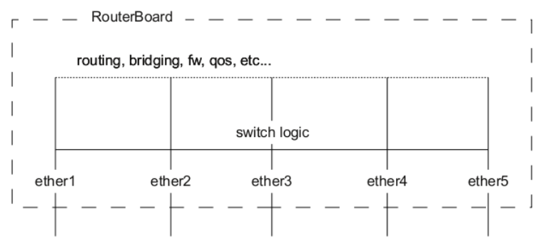
A packet that is received by one of the ports always passes through the switch logic first. Switch logic decides which ports the packet should be going to (most commonly this decision is made based on the destination MAC address of a packet, but there might be other criteria that might be involved based on the packet and the configuration). In most cases the packet will not be visible to RouterOS (only statistics will show that a packet has passed through), this is because the packet was already processed by the switch chip and never reached the CPU.
Though it is possible in certain situations to allow a packet to be processed by the CPU, this is usually called a packet forwarding to the switch CPU port (or the bridge interface in bridge VLAN filtering scenario). This allows the CPU to process the packet and lets the CPU to forward the packet. Passing the packet to the CPU port will give you the opportunity to route packets to different networks, perform traffic control and other software related packet processing actions. To allow a packet to be processed by the CPU, you need to make certain configuration changes depending on your needs and on the device you are using (most commonly passing packets to the CPU are required for VLAN filtering setups). Check the manual page for your specific device:
- CRS1xx/2xx series switches
- CRS3xx, CRS5xx series switches and CCR2116, CCR2216 routers
- non-CRS series switches
Certain bridge and Ethernet port properties are directly related to switch chip settings. Changing such properties can trigger a switch chip reset, temporarily disabling all Ethernet ports that are on the switch chip for the settings to take effect. This must be taken into account whenever changing properties in production environments. Such properties include DHCP Snooping, IGMP Snooping, VLAN filtering, L2MTU, Flow Control, and others. The exact settings that can trigger a switch chip reset depend on the device's model.
The CRS1xx/2xx series switches support multiple hardware offloaded bridges per switch chip. All other devices support only one hardware offloaded bridge per switch chip. Use the hw=yes/no parameter to select which bridge will use hardware offloading.
Example
Port switching with bridge configuration and enabled hardware offloading:
/interface bridge
add name=bridge1
/interface bridge port
add bridge=bridge1 interface=ether2 hw=yes
add bridge=bridge1 interface=ether3 hw=yes
add bridge=bridge1 interface=ether4 hw=yes
add bridge=bridge1 interface=ether5 hw=yes
Make sure that hardware offloading is enabled and active by checking the "H" flag:
[admin@MikroTik] /interface bridge port print
Flags: X - disabled, I - inactive, D - dynamic, H - hw-offload
 #     INTERFACE       BRIDGE       HW  PVID PRIORITY  PATH-COST INTERNAL-PATH-COST    HORIZON
 0   H ether2          bridge1      yes    1     0x80         10                 10       none
 1   H ether3          bridge1      yes    1     0x80         10                 10       none
 2   H ether4          bridge1      yes    1     0x80         10                 10       none
 3   H ether5          bridge1      yes    1     0x80         10                 10       none
Port switching in RouterOS v6.41 and newer is done using the bridge configuration. Prior to RouterOS v6.41 port switching was done using the master-port property.
Bridge VLAN Filtering
Bridge VLAN Filtering provides VLAN-aware Layer 2 forwarding and VLAN tag modifications within the bridge. This set of features makes bridge operation more similar to a traditional Ethernet switch and allows overcoming Spanning Tree compatibility issues compared to the configuration when VLAN interfaces are bridged. Bridge VLAN Filtering configuration is highly recommended to comply with STP (IEEE 802.1D), RSTP (IEEE 802.1W) standards and is mandatory to enable MSTP (IEEE 802.1s) support in RouterOS.
The main VLAN setting is vlan-filtering which globally controls VLAN-awareness and VLAN tag processing in the bridge. If vlan-filtering=no is configured, the bridge ignores VLAN tags, works in a shared-VLAN-learning (SVL) mode, and cannot modify VLAN tags of packets. Turning on vlan-filtering enables all bridge VLAN related functionality and independent-VLAN-learning (IVL) mode. Besides joining the ports for Layer2 forwarding, the bridge itself is also an interface therefore it has Port VLAN ID (pvid).
Currently, CRS3xx, CRS5xx series switches, CCR2116, CCR2216 routers and RTL8367, 88E6393X, 88E6191X, 88E6190, MT7621 and MT7531 switch chips (since RouterOS v7) are capable of using bridge VLAN filtering and hardware offloading at the same time, other devices will not be able to use the benefits of a built-in switch chip when bridge VLAN filtering is enabled. Other devices should be configured according to the method described in the Basic VLAN switching guide. If an improper configuration method is used, your device can cause throughput issues in your network.
Bridge VLAN table
Bridge VLAN table represents per-VLAN port mapping with an egress VLAN tag action. The tagged ports send out frames with a corresponding VLAN ID tag. The untagged ports remove a VLAN tag before sending out frames. Bridge ports with frame-types set to admit-all or admit-only-untagged-and-priority-tagged will be automatically added as untagged ports for the pvid VLAN.
Sub-menu: /interface bridge vlan
| Property | Description |
|---|---|
| bridge (name; Default: none) | The bridge interface which the respective VLAN entry is intended for. |
| disabled (yes | no; Default: no) | Enables or disables Bridge VLAN entry. |
| tagged (interfaces; Default: none) | Interface list with a VLAN tag adding action in egress. This setting accepts comma-separated values. e.g. tagged=ether1,ether2. |
| untagged (interfaces; Default: none) | Interface list with a VLAN tag removing action in egress. This setting accepts comma-separated values. e.g. untagged=ether3,ether4 |
| vlan-ids (integer 1..4094; Default: 1) | The list of VLAN IDs for certain port configuration. This setting accepts the VLAN ID range as well as comma-separated values. e.g. vlan-ids=100-115,120,122,128-130. |
The vlan-ids parameter can be used to specify a set or range of VLANs, but specifying multiple VLANs in a single bridge VLAN table entry should only be used for ports that are tagged ports. In case multiple VLANs are specified for access ports, then tagged packets might get sent out as untagged packets through the wrong access port, regardless of the PVID value.
Make sure you have added all needed interfaces to the bridge VLAN table when using bridge VLAN filtering. For routing functions to work properly on the same device through ports that use bridge VLAN filtering, you will need to allow access to the bridge interface (this automatically include a switch-cpu port when HW offloaded vlan-filtering is used, e.g. on CRS3xx series switches), this can be done by adding the bridge interface itself to the VLAN table, for tagged traffic you will need to add the bridge interface as a tagged port and create a VLAN interface on the bridge interface. Examples can be found in the inter-VLAN routing and Management port sections.
When allowing access to the CPU, you are allowing access from a certain port to the actual router/switch, this is not always desirable. Make sure you implement proper firewall filter rules to secure your device when access to the CPU is allowed from a certain VLAN ID and port, use firewall filter rules to allow access to only certain services.
Improperly configured bridge VLAN filtering can cause security issues, make sure you fully understand how Bridge VLAN table works before deploying your device into production environments.
Bridge port settings
Each bridge port have multiple VLAN related settings, that can change untagged VLAN membership, VLAN tagging/untagging behavior and packet filtering based on VLAN tag presence.
Sub-menu: /interface bridge port
| Property | Description |
|---|---|
| frame-types (admit-all | admit-only-untagged-and-priority-tagged | admit-only-vlan-tagged; Default: admit-all) | Specifies allowed ingress frame types on a bridge port. This property only has an effect when vlan-filtering is set to yes. |
| ingress-filtering (yes | no; Default: yes) | Enables or disables VLAN ingress filtering, which checks if the ingress port is a member of the received VLAN ID in the bridge VLAN table. Should be used with frame-types to specify if the ingress traffic should be tagged or untagged. This property only has effect when vlan-filtering is set to yes. The setting is enabled by default since RouterOS v7. |
| pvid (integer 1..4094; Default: 1) | Port VLAN ID (pvid) specifies which VLAN the untagged ingress traffic is assigned to. This property only has an effect when vlan-filtering is set to yes. |
| tag-stacking (yes | no; Default: no) | Forces all packets to be treated as untagged packets. Packets on ingress port will be tagged with another VLAN tag regardless if a VLAN tag already exists, packets will be tagged with a VLAN ID that matches the pvid value and will use EtherType that is specified in ether-type. This property only has effect when vlan-filtering is set to yes. |
Bridge host table
Bridge host table allows monitoring learned MAC addresses. When vlan-filtering is enabled, it shows learned VLAN ID as well (enabled independent-VLAN-learning or IVL).
[admin@MikroTik] > /interface bridge host print where !local
Flags: X - disabled, I - invalid, D - dynamic, L - local, E - external
 #       MAC-ADDRESS        VID ON-INTERFACE       BRIDGE
 0   D   CC:2D:E0:E4:B3:AA  300 ether3             bridge1
 1   D   CC:2D:E0:E4:B3:AB  400 ether4             bridge1
VLAN Example - Trunk and Access Ports
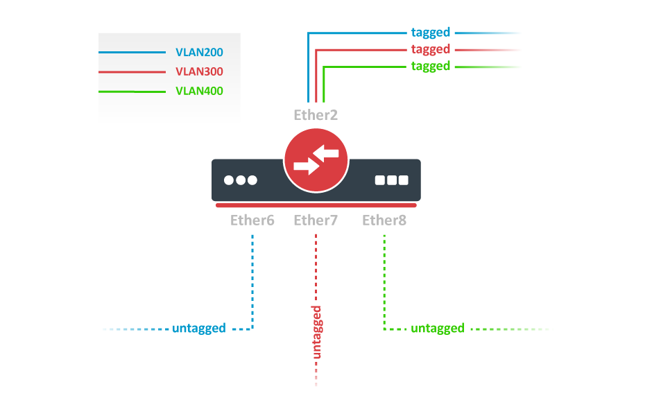
Create a bridge with disabled vlan-filtering to avoid losing access to the device before VLANs are completely configured. If you need a management access to the bridge, see the Management access configuration section.
/interface bridge
add name=bridge1 vlan-filtering=no
Add bridge ports and specify pvid for access ports to assign their untagged traffic to the intended VLAN. Use frame-types setting to accept only tagged or untagged packets.
/interface bridge port
add bridge=bridge1 interface=ether2 frame-types=admit-only-vlan-tagged
add bridge=bridge1 interface=ether6 pvid=200 frame-types=admit-only-untagged-and-priority-tagged
add bridge=bridge1 interface=ether7 pvid=300 frame-types=admit-only-untagged-and-priority-tagged
add bridge=bridge1 interface=ether8 pvid=400 frame-types=admit-only-untagged-and-priority-tagged
Add Bridge VLAN entries and specify tagged ports in them. Bridge ports with frame-types set to admit-only-untagged-and-priority-tagged will be automatically added as untagged ports for the pvid VLAN.
/interface bridge vlan
add bridge=bridge1 tagged=ether2 vlan-ids=200
add bridge=bridge1 tagged=ether2 vlan-ids=300
add bridge=bridge1 tagged=ether2 vlan-ids=400
In the end, when VLAN configuration is complete, enable Bridge VLAN Filtering.
/interface bridge set bridge1 vlan-filtering=yes
Optional step is to set frame-types=admit-only-vlan-tagged on the bridge interface in order to disable the default untagged VLAN 1 (pvid=1).
/interface bridge set bridge1 frame-types=admit-only-vlan-tagged
VLAN Example - Trunk and Hybrid Ports
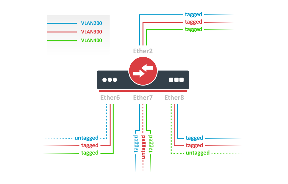
Create a bridge with disabled vlan-filtering to avoid losing access to the router before VLANs are completely configured. If you need a management access to the bridge, see the Management access configuration section.
/interface bridge
add name=bridge1 vlan-filtering=no
Add bridge ports and specify pvid on hybrid VLAN ports to assign untagged traffic to the intended VLAN. Use frame-types setting to accept only tagged packets on ether2.
/interface bridge port
add bridge=bridge1 interface=ether2 frame-types=admit-only-vlan-tagged
add bridge=bridge1 interface=ether6 pvid=200
add bridge=bridge1 interface=ether7 pvid=300
add bridge=bridge1 interface=ether8 pvid=400
Add Bridge VLAN entries and specify tagged ports in them. In this example egress VLAN tagging is done on ether6,ether7,ether8 ports too, making them into hybrid ports. Bridge ports with frame-types set to admit-all will be automatically added as untagged ports for the pvid VLAN.
/interface bridge vlan
add bridge=bridge1 tagged=ether2,ether7,ether8 vlan-ids=200
add bridge=bridge1 tagged=ether2,ether6,ether8 vlan-ids=300
add bridge=bridge1 tagged=ether2,ether6,ether7 vlan-ids=400
In the end, when VLAN configuration is complete, enable Bridge VLAN Filtering.
/interface bridge set bridge1 vlan-filtering=yes
Optional step is to set frame-types=admit-only-vlan-tagged on the bridge interface in order to disable the default untagged VLAN 1 (pvid=1).
/interface bridge set bridge1 frame-types=admit-only-vlan-tagged
You don't have to add access ports as untagged ports, because they will be added dynamically as an untagged port with the VLAN ID that is specified in pvid, you can specify just the trunk port as a tagged port. All ports that have the same pvid set will be added as untagged ports in a single entry. You must take into account that the bridge itself is a port and it also has a pvid value, this means that the bridge port also will be added as an untagged port for the ports that have the same pvid. You can circumvent this behavior by either setting different pvid on all ports (even the trunk port and bridge itself), or to use frame-type set to accept-only-vlan-tagged.
VLAN Example - InterVLAN Routing by Bridge
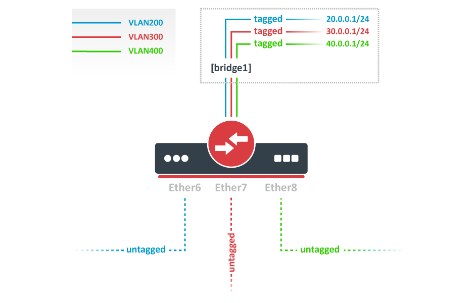
Create a bridge with disabled vlan-filtering to avoid losing access to the router before VLANs are completely configured. If you need a management access to the bridge, see the Management access configuration section.
/interface bridge
add name=bridge1 vlan-filtering=no
Add bridge ports and specify pvid for VLAN access ports to assign their untagged traffic to the intended VLAN. Use frame-types setting to accept only untagged packets.
/interface bridge port
add bridge=bridge1 interface=ether6 pvid=200 frame-types=admit-only-untagged-and-priority-tagged
add bridge=bridge1 interface=ether7 pvid=300 frame-types=admit-only-untagged-and-priority-tagged
add bridge=bridge1 interface=ether8 pvid=400 frame-types=admit-only-untagged-and-priority-tagged
Add Bridge VLAN entries and specify tagged ports in them. In this example bridge1 interface is the VLAN trunk that will send traffic further to do InterVLAN routing. Bridge ports with frame-types set to admit-only-untagged-and-priority-tagged will be automatically added as untagged ports for the pvid VLAN.
/interface bridge vlan
add bridge=bridge1 tagged=bridge1 vlan-ids=200
add bridge=bridge1 tagged=bridge1 vlan-ids=300
add bridge=bridge1 tagged=bridge1 vlan-ids=400
Configure VLAN interfaces on the bridge1 to allow handling of tagged VLAN traffic at routing level and set IP addresses to ensure routing between VLANs as planned.
/interface vlan
add interface=bridge1 name=VLAN200 vlan-id=200
add interface=bridge1 name=VLAN300 vlan-id=300
add interface=bridge1 name=VLAN400 vlan-id=400

/ip address
add address=20.0.0.1/24 interface=VLAN200
add address=30.0.0.1/24 interface=VLAN300
add address=40.0.0.1/24 interface=VLAN400
In the end, when VLAN configuration is complete, enable Bridge VLAN Filtering:
/interface bridge set bridge1 vlan-filtering=yes
Optional step is to set frame-types=admit-only-vlan-tagged on the bridge interface in order to disable the default untagged VLAN 1 (pvid=1).
/interface bridge set bridge1 frame-types=admit-only-vlan-tagged
Since RouterOS v7, it is possible to route traffic using the L3 HW offloading on certain devices. See more details on L3 Hardware Offloading.
Management access configuration
There are multiple ways to set up management access on a device that uses bridge VLAN filtering. Below are some of the most popular approaches to properly enable access to a router/switch. Start by creating a bridge without VLAN filtering enabled:
/interface bridge add name=bridge1 vlan-filtering=no
Untagged access without VLAN filtering
In case VLAN filtering will not be used and access with untagged traffic is desired, the only requirement is to create an IP address on the bridge interface.
/ip address add address=192.168.99.1/24 interface=bridge1
Tagged access without VLAN filtering
In case VLAN filtering will not be used and access with tagged traffic is desired, create a routable VLAN interface on the bridge and add an IP address on the VLAN interface.
/interface vlan add interface=bridge1 name=MGMT vlan-id=99 /ip address add address=192.168.99.1/24 interface=MGMT
Tagged access with VLAN filtering
In case VLAN filtering is used and access with tagged traffic is desired, additional steps are required. In this example, VLAN 99 will be used to access the device. A VLAN interface on the bridge must be created and an IP address must be assigned to it.
/interface vlan add interface=bridge1 name=MGMT vlan-id=99 /ip address add address=192.168.99.1/24 interface=MGMT
For example, if you want to allow access to the device from ports ether3, ether4, sfp-sfpplus1 using tagged VLAN 99 traffic, then you must add this entry to the VLAN table. Note that the bridge1 interface is also included in the tagged port list:
/interface bridge vlan add bridge=bridge1 tagged=bridge1,ether3,ether4,sfp-sfpplus1 vlan-ids=99
After that you can enable VLAN filtering:
/interface bridge set bridge1 vlan-filtering=yes
Untagged access with VLAN filtering
In case VLAN filtering is used and access with untagged traffic is desired, the VLAN interface must use the same VLAN ID as the untagged port VLAN ID (pvid). Just like in the previous example, start by creating a VLAN interface on the bridge and add an IP address for the VLAN.
/interface vlan add interface=bridge1 name=MGMT vlan-id=99 /ip address add address=192.168.99.1/24 interface=MGMT
For example, untagged ports ether2 and ether3 should be able to communicate with the VLAN 99 interface using untagged traffic. In order to achieve this, these ports should be configured with the pvid that matches the VLAN ID on management VLAN. Note that the bridge1 interface is a tagged port member, you can configure additional tagged ports if necessary (see the previous example).
/interface bridge port set [find interface=ether2] pvid=99 set [find interface=ether3] pvid=99 /interface bridge vlan add bridge=bridge1 tagged=bridge1 untagged=ether2,ether3 vlan-ids=99
After that you can enable VLAN filtering:
/interface bridge set bridge1 vlan-filtering=yes
Changing untagged VLAN for the bridge interface
In case VLAN filtering is used, it is possible to change the untagged VLAN ID for the bridge interface using the pvid setting. Note that creating routable VLAN interfaces and allowing tagged traffic on the bridge is a more flexible and generally recommended option.
First, create an IP address on the bridge interface.
/ip address add address=192.168.99.1/24 interface=bridge1
For example, untagged bridge1 traffic should be able to communicate with untagged ether2 and ether3 ports and tagged sfp-sfpplus1 port in VLAN 99. In order to achieve this, bridge1, ether2, ether3 should be configured with the same pvid and sfp-sfpplus1 added as a tagged member.
/interface bridge set [find name=bridge1] pvid=99 /interface bridge port set [find interface=ether2] pvid=99 set [find interface=ether3] pvid=99 /interface bridge vlan add bridge=bridge1 tagged=sfp-sfpplus1 untagged=bridge1,ether2,ether3 vlan-ids=99
After that you can enable VLAN filtering:
/interface bridge set bridge1 vlan-filtering=yes
If the connection to the router/switch through an IP address is not required, then steps adding an IP address can be skipped since a connection to the router/switch through Layer2 protocols (e.g. MAC-telnet) will be working either way.
VLAN Tunneling (QinQ)
Since RouterOS v6.43 the RouterOS bridge is IEEE 802.1ad compliant and it is possible to filter VLAN IDs based on Service VLAN ID (0x88a8) rather than Customer VLAN ID (0x8100). The same principles can be applied as with IEEE 802.1Q VLAN filtering (the same setup examples can be used). Below is a topology for a common Provider bridge:
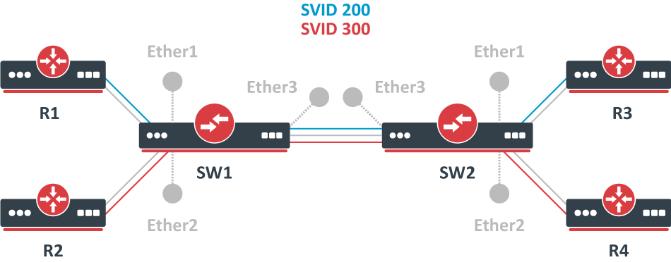
In this example, R1, R2, R3, and R4 might be sending any VLAN tagged traffic by 802.1Q (CVID), but SW1 and SW2 needs isolate traffic between routers in a way that R1 is able to communicate only with R3, and R2 is only able to communicate with R4. To do so, you can tag all ingress traffic with an SVID and only allow these VLANs on certain ports. Start by enabling the service tag 0x88a8, introduced by 802.1ad, on the bridge. Use these commands on SW1 and SW2:
/interface bridge add name=bridge1 vlan-filtering=no ether-type=0x88a8
In this setup, ether1 and ether2 are going to be access ports (untagged), use the pvid parameter to tag all ingress traffic on each port, use these commands on SW1 and SW2:
/interface bridge port add interface=ether1 bridge=bridge1 pvid=200 add interface=ether2 bridge=bridge1 pvid=300 add interface=ether3 bridge=bridge1
Specify tagged and untagged ports in the bridge VLAN table, use these commands on SW1 and SW2:
/interface bridge vlan add bridge=bridge1 tagged=ether3 untagged=ether1 vlan-ids=200 add bridge=bridge1 tagged=ether3 untagged=ether2 vlan-ids=300
When the bridge VLAN table is configured, you can enable bridge VLAN filtering, use these commands on SW1 and SW2:
/interface bridge set bridge1 vlan-filtering=yes
By enabling vlan-filtering you will be filtering out traffic destined to the CPU, before enabling VLAN filtering you should make sure that you set up a Management port.
Note, that if you are using the new EtherType/TPID 0x88a8 (service tag) and you also need a VLAN interface for your Service VLAN, you will also have to apply the use-service-tag parameter on the VLAN interface.
When ether-type=0x8100 is configured, the bridge checks the outer VLAN tag and sees if it is using EtherType 0x8100. If the bridge receives a packet with an outer tag that has a different EtherType, it will mark the packet as untagged. Since RouterOS only checks the outer tag of a packet, it is not possible to filter 802.1Q packets when the 802.1ad protocol is used.
Currently, only CRS3xx, CRS5xx series switches and CCR2116, CCR2216 routers are capable of hardware offloaded VLAN filtering using the Service tag, EtherType/TPID 0x88a8.
Devices with switch chip Marvell-98DX3257 (e.g. CRS354 series) do not support VLAN filtering on 1Gbps Ethernet interfaces for other VLAN types (0x88a8 and 0x9100).
Tag stacking
Since RouterOS v6.43 it is possible to forcefully add a new VLAN tag over any existing VLAN tags, this feature can be used to achieve a CVID stacking setup, where a CVID (0x8100) tag is added before an existing CVID tag. This type of setup is very similar to the Provider bridge setup, to achieve the same setup but with multiple CVID tags (CVID stacking) we can use the same topology:
In this example R1, R2, R3, and R4 might be sending any VLAN tagged traffic, it can be 802.1ad, 802.1Q or any other type of traffic, but SW1 and SW2 needs isolate traffic between routers in a way that R1 is able to communicate only with R3, and R2 is only able to communicate with R4. To do so, you can tag all ingress traffic with a new CVID tag and only allow these VLANs on certain ports. Start by selecting the proper EtherType, use these commands on SW1 and SW2:
/interface bridge add name=bridge1 vlan-filtering=no ether-type=0x8100
In this setup, ether1 and ether2 will ignore any VLAN tags that are present and add a new VLAN tag, use the pvid parameter to tag all ingress traffic on each port and allow tag-stacking on these ports, use these commands on SW1 and SW2:
/interface bridge port add interface=ether1 bridge=bridge1 pvid=200 tag-stacking=yes add interface=ether2 bridge=bridge1 pvid=300 tag-stacking=yes add interface=ether3 bridge=bridge1
Specify tagged and untagged ports in the bridge VLAN table, you only need to specify the VLAN ID of the outer tag, use these commands on SW1 and SW2:
/interface bridge vlan add bridge=bridge1 tagged=ether3 untagged=ether1 vlan-ids=200 add bridge=bridge1 tagged=ether3 untagged=ether2 vlan-ids=300
When the bridge VLAN table is configured, you can enable bridge VLAN filtering, which is required in order for the pvid parameter to have any effect, use these commands on SW1 and SW2:
/interface bridge set bridge1 vlan-filtering=yes
By enabling vlan-filtering you will be filtering out traffic destined to the CPU, before enabling VLAN filtering you should make sure that you set up a Management port.
MVRP
Multiple VLAN Registration protocol (MVRP) is a protocol based on Multiple Registration Protocol (MRP) which allows to register attributes (VLAN IDs in case of MVRP) with other members of Bridged LAN.
An MRP application can make or withdraw declarations of attributes which result in registration or leaving of those attributes with other MRP participants.
Here's how it works.
MRP consists of two parts:
Applicant - responsible for sending declarations (or leaves). Its behavior can be configured on a per-port basis using the setting called
mvrp-applicant-state, and per-VLAN using themvrp-forbiddensetting.Registrar - responsible for registering incoming declarations. Its configuration can be set per-port using the
mvrp-registrar-statesetting, and per-VLAN using themvrp-forbiddensetting.
Registration Propagation: Incoming registration on a bridge port dynamically makes that specific port a tagged VLAN member. Additionally, the attributes associated with this registration are spread to all active (forwarding) bridge ports as a declaration.
Declaration Operation: In case of MVRP, the configured VLAN's get declared on each port, but they will only get configured as members of those VLAN's when a declaration is received from the LAN (Registrar will register the VLAN). From the perspective of an end-station, a single declaration will be registered on each upstream port across the entire LAN. When another end-station declares the same attribute, a path of registrations will be made between the two (or more) end stations, see the picture below.
MVRP helps to dynamically propagate VLAN information throughout the bridged network and configure VLANs only on the needed ports. This makes the network efficient by avoiding unnecessary traffic flooding.
As noted before, MVRP is only active on ports that are forwarding. In case of MSTP declarations and registrations are made only if the port is forwarding in the MSTI in which VLAN is mapped.
The point-to-point ports speed up the process of registration (or leaving). Manually configuring point-to-point=yes can be advantageous for non-Ethernet interfaces.
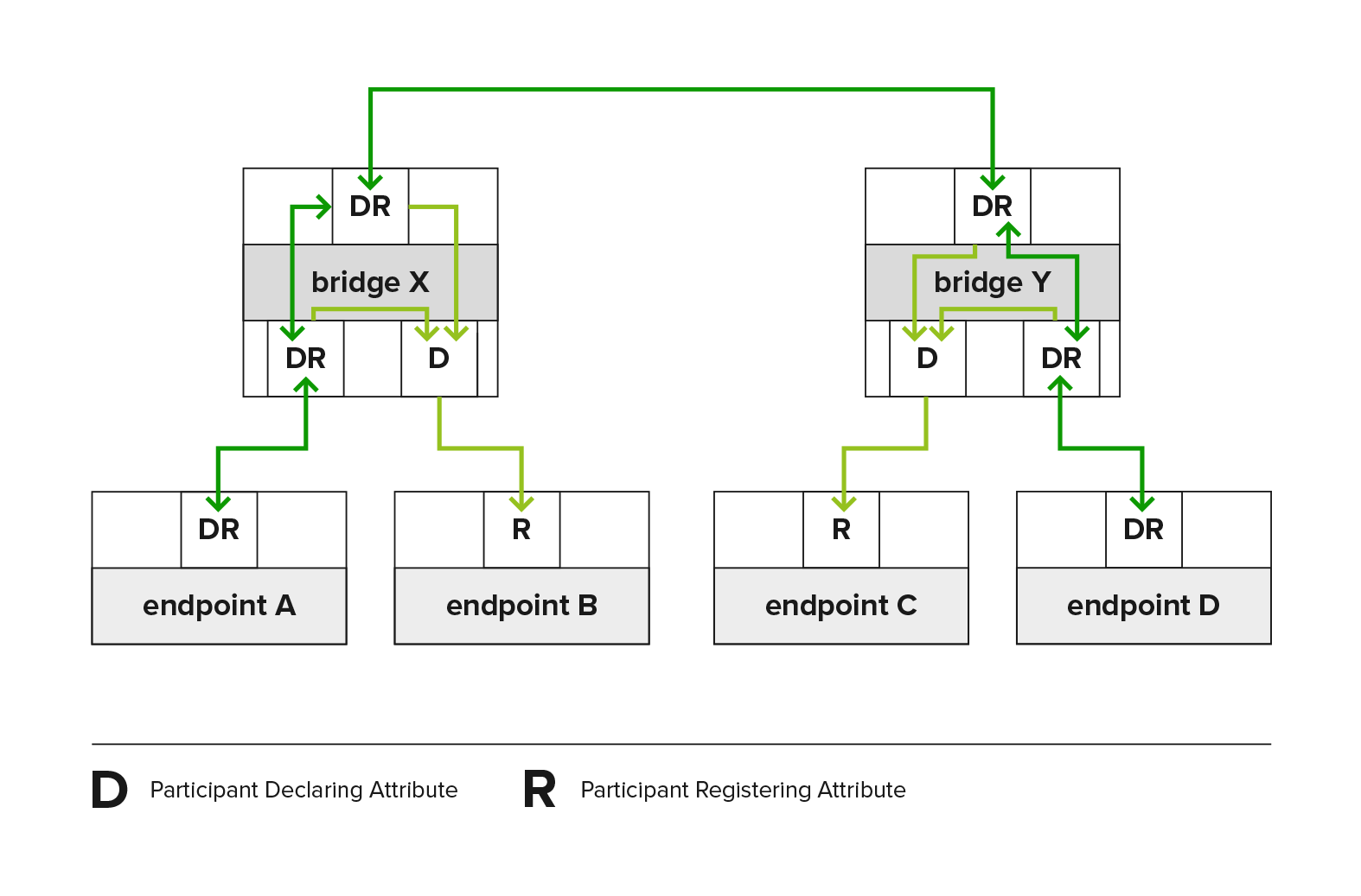
Property Reference
Sub-menu: /interface bridge
Property | Description |
|---|---|
mvrp (yes | no; Default: no) | Enables MVRP for bridge. It ensures that the MAC address 01:80:C2:00:00:21 is trapped and not forwarded, the |
Sub-menu: /interface bridge port
The port menu enables control over the applicant and registrar settings on a per-port basis.
Property | Description |
|---|---|
mvrp-applicant-state (non-participant | normal-participant; Default: normal-participant) | MVRP applicant options:
|
mvrp-registrar-state (fixed | normal; Default: normal) | MVRP registrar options:
|
To monitor the currently declared and registered VLAN IDs, use the monitor command.
[admin@MikroTik] > interface/bridge/port monitor [find interface=sfp-sfpplus1]
interface: sfp-sfpplus1
status: in-bridge
port-number: 1
role: designated-port
edge-port: no
edge-port-discovery: yes
point-to-point-port: yes
external-fdb: no
sending-rstp: yes
learning: yes
forwarding: yes
actual-path-cost: 2000
hw-offload-group: switch1
declared-vlan-ids: 1,10,20-21
registered-vlan-ids: 1,10,20,30-33 Sub-menu: /interface bridge vlan
All ports that are members of static VLANs or dynamic untagged VLANs created by the port pvid setting are treated as "fixed." Meaning the registrar disregards all MRP messages and remains registered (IN) for those VLANs.
When VLAN is neither manually configured nor created by the port pvid setting, incoming registrations on a bridge port can dynamically designate that specific port as a tagged VLAN member. The mvrp-forbidden feature allows creating a list of ports that are restricted from registering into a specific VLAN ID.
VLANs that are static or dynamic will be declared by the applicants unless this functionality is disabled by the port's mvrp-applicant-state, or by VLAN's mvrp-forbidden setting.
Property | Description |
|---|---|
mvrp-forbidden (interfaces; Default: ) | Ports that ignore all MRP messages and remains Not Registered (MT), as well as disables applicant from declaring specific VLAN ID. |
Sub-menu: /interface bridge vlan mvrp
The MVRP attributes menu can be used to see internal MVRP attribute states, as specified in the IEEE 802.1Q-2011.
Property | Description |
|---|---|
applicant-state | The Applicant state machine that declares attributes. Its state can be VO, VP, VN, AN, AA, QA, LA, AO, QO, AP, QP, or LO. Each state consists of two letters. The first letter indicates the state:
The second letter indicates the membership state:
For example, VP indicates "Very anxious, Passive member." |
registrar-state | The Registrar state machine that records the registration state of attributes declared by other participants. Its state can be IN, LV, or MT:
|
[admin@Mikrotik] /interface/bridge/vlan/mvrp print where vlan-id=10 Columns: BRIDGE, PORT, VLAN-ID, REGISTRAR-STATE, APPLICANT-STATE, LAST-EVENT # BRIDGE PORT VLAN-ID REGISTRAR-STATE APPLICANT-STATE LAST-EVENT 1 bridge67 sfp-sfpplus1 10 IN Quiet Active JoinIn 9 bridge67 sfp-sfpplus5 10 MT Quiet Active JoinEmpty 17 bridge67 sfp-sfpplus9 10 MT Quiet Active JoinEmpty 25 bridge67 sfp-sfpplus13 10 IN Quiet Active JoinIn
Fast Forward
Fast Forward allows forwarding packets faster under special conditions. When Fast Forward is enabled, then the bridge can process packets even faster since it can skip multiple bridge-related checks, including MAC learning. Below you can find a list of conditions that MUST be met in order for Fast Forward to be active:
- Bridge has
fast-forwardset toyes - Bridge has only 2 running ports
- Both bridge ports support Fast Path, Fast Path is active on ports and globally on the bridge
- Bridge Hardware Offloading is disabled
- Bridge VLAN Filtering is disabled
- Bridge DHCP snooping is disabled
unknown-multicast-floodis set toyesunknown-unicast-floodis set toyesbroadcast-floodis set toyes- MAC address for the bridge matches with a MAC address from one of the bridge slave ports
horizonfor both ports is set tonone
Fast Forward disables MAC learning, this is by design to achieve faster packet forwarding. MAC learning prevents traffic from flooding multiple interfaces, but MAC learning is not needed when a packet can only be sent out through just one interface.
Fast Forward is disabled when hardware offloading is enabled. Hardware offloading can achieve full write-speed performance when it is active since it will use the built-in switch chip (if such exists on your device), fast forward uses the CPU to forward packets. When comparing throughput results, you would get such results: Hardware offloading > Fast Forward > Fast Path > Slow Path.
It is possible to check how many packets where processed by Fast Forward:
[admin@MikroTik] /interface bridge settings> pr use-ip-firewall: no use-ip-firewall-for-vlan: no use-ip-firewall-for-pppoe: no allow-fast-path: yes bridge-fast-path-active: yes bridge-fast-path-packets: 0 bridge-fast-path-bytes: 0 bridge-fast-forward-packets: 16423 bridge-fast-forward-bytes: 24864422
If packets are processed by Fast Path, then Fast Forward is not active. Packet count can be used as an indicator of whether Fast Forward is active or not.
Since RouterOS 6.44 it is possible to monitor Fast Forward status, for example:
[admin@MikroTik] /interface bridge monitor bridge1 state: enabled current-mac-address: B8:69:F4:C9:EE:D7 root-bridge: yes root-bridge-id: 0x8000.B8:69:F4:C9:EE:D7 root-path-cost: 0 root-port: none port-count: 2 designated-port-count: 2 fast-forward: yes
Disabling or enabling fast-forward will temporarily disable all bridge ports for settings to take effect. This must be taken into account whenever changing this property on production environments since it can cause all packets to be temporarily dropped.
IGMP/MLD Snooping
The bridge supports IGMP/MLD snooping. It controls multicast streams and prevents multicast flooding on unnecessary ports. Its settings are placed in the bridge menu and it works independently in every bridge interface. Software-driven implementation works on all devices with RouterOS, but CRS3xx, CRS5xx series switches, CCR2116, CR2216 routers, and 88E6393X, 88E6191X, 88E6190 switch chips also support IGMP/MLD snooping with hardware offloading. See more details on IGMP/MLD snooping manual.
DHCP Snooping and DHCP Option 82
DHCP Snooping and DHCP Option 82 is supported by bridge. The DHCP Snooping is a Layer2 security feature, that limits unauthorized DHCP servers from providing malicious information to users. In RouterOS, you can specify which bridge ports are trusted (where known DHCP server resides and DHCP messages should be forwarded) and which are untrusted (usually used for access ports, received DHCP server messages will be dropped). The DHCP Option 82 is additional information (Agent Circuit ID and Agent Remote ID) provided by DHCP Snooping enabled devices that allow identifying the device itself and DHCP clients.
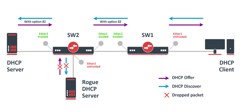
In this example, SW1 and SW2 are DHCP Snooping, and Option 82 enabled devices. First, we need to create a bridge, assign interfaces and mark trusted ports. Use these commands on SW1:
/interface bridge add name=bridge /interface bridge port add bridge=bridge interface=ether1 add bridge=bridge interface=ether2 trusted=yes
For SW2, the configuration will be similar, but we also need to mark ether1 as trusted, because this interface is going to receive DHCP messages with Option 82 already added. You need to mark all ports as trusted if they are going to receive DHCP messages with added Option 82, otherwise these messages will be dropped. Also, we add ether3 to the same bridge and leave this port untrusted, imagine there is an unauthorized (rogue) DHCP server. Use these commands on SW2:
/interface bridge add name=bridge /interface bridge port add bridge=bridge interface=ether1 trusted=yes add bridge=bridge interface=ether2 trusted=yes add bridge=bridge interface=ether3
Then we need to enable DHCP Snooping and Option 82. In case your DHCP server does not support DHCP Option 82 or you do not implement any Option 82 related policies, this option can be disabled. Use these commands on SW1 and SW2:
/interface bridge set [find where name="bridge"] dhcp-snooping=yes add-dhcp-option82=yes
Now both devices will analyze what DHCP messages are received on bridge ports. The SW1 is responsible for adding and removing the DHCP Option 82. The SW2 will limit rogue DHCP server from receiving any discovery messages and drop malicious DHCP server messages from ether3.
Currently, CRS3xx, CRS5xx series switches, CCR2116, CR2216 routers, and 88E6393X, 88E6191X, 88E6190 switch chips fully support hardware offloaded DHCP Snooping and Option 82. For CRS1xx and CRS2xx series switches it is possible to use DHCP Snooping along with VLAN switching, but then you need to make sure that DHCP packets are sent out with the correct VLAN tag using egress ACL rules. Other devices are capable of using DHCP Snooping and Option 82 features along with hardware offloading, but you must make sure that there is no VLAN-related configuration applied on the device, otherwise, DHCP Snooping and Option 82 might not work properly. See the Bridge Hardware Offloading section with supported features.
For CRS3xx, CRS5xx series switches and CCR2116, CR2216 routers DHCP snooping will not work when hardware offloading bonding interfaces are created.
Controller Bridge and Port Extender
Controller Bridge (CB) and Port Extender (PE) is an IEEE 802.1BR standard implementation in RouterOS for CRS3xx, CRS5xx series switches and CCR2116, CCR2216 routers. It allows virtually extending the CB ports with a PE device and managing these extended interfaces from a single controlling device. Such configuration provides a simplified network topology, flexibility, increased port density, and ease of manageability. See more details on Controller Bridge and Port Extender manual.
Bridge Firewall
The bridge firewall implements packet filtering and thereby provides security functions that are used to manage data flow to, from, and through the bridge.
Packet flow diagram shows how packets are processed through the router. It is possible to force bridge traffic to go through /ip firewall filter rules (see the bridge settings).
There are two bridge firewall tables:
- filter - bridge firewall with three predefined chains:
- input - filters packets, where the destination is the bridge (including those packets that will be routed, as they are destined to the bridge MAC address anyway)
- output - filters packets, which come from the bridge (including those packets that has been routed normally)
- forward - filters packets, which are to be bridged (note: this chain is not applied to the packets that should be routed through the router, just to those that are traversing between the ports of the same bridge)
- nat - bridge network address translation provides ways for changing source/destination MAC addresses of the packets traversing a bridge. Has two built-in chains:
- srcnat - used for "hiding" a host or a network behind a different MAC address. This chain is applied to the packets leaving the router through a bridged interface
- dstnat - used for redirecting some packets to other destinations
You can put packet marks in bridge firewall (filter and NAT), which are the same as the packet marks in IP firewall configured by '/ip firewall mangle'. In this way, packet marks put by bridge firewall can be used in 'IP firewall', and vice versa.
General bridge firewall properties are described in this section. Some parameters that differ between nat and filter rules are described in further sections.
Sub-menu: /interface bridge filter, /interface bridge nat
| Property | Description |
|---|---|
| 802.3-sap (integer; Default: ) | DSAP (Destination Service Access Point) and SSAP (Source Service Access Point) are 2 one-byte fields, which identify the network protocol entities which use the link-layer service. These bytes are always equal. Two hexadecimal digits may be specified here to match an SAP byte. |
| 802.3-type (integer; Default: ) | Ethernet protocol type, placed after the IEEE 802.2 frame header. Works only if 802.3-sap is 0xAA (SNAP - Sub-Network Attachment Point header). For example, AppleTalk can be indicated by the SAP code of 0xAA followed by a SNAP type code of 0x809B. |
| action (accept | drop | jump | log | mark-packet | passthrough | return | set-priority; Default: ) | Action to take if the packet is matched by the rule:
|
| arp-dst-address (IP address; Default: ) | ARP destination IP address. |
| arp-dst-mac-address (MAC address; Default: ) | ARP destination MAC address. |
| arp-gratuitous (yes | no; Default: ) | Matches ARP gratuitous packets. |
| arp-hardware-type (integer; Default: 1) | ARP hardware type. This is normally Ethernet (Type 1). |
| arp-opcode (arp-nak | drarp-error | drarp-reply | drarp-request | inarp-reply | inarp-request | reply | reply-reverse | request | request-reverse; Default: ) | ARP opcode (packet type)
|
| arp-packet-type (integer 0..65535 | hex 0x0000-0xffff; Default: ) | ARP Packet Type. |
| arp-src-address (IP address; Default: ) | ARP source IP address. |
| arp-src-mac-address (MAC addres; Default: ) | ARP source MAC address. |
| chain (text; Default: ) | Bridge firewall chain, which the filter is functioning in (either a built-in one, or a user-defined one). |
| dst-address (IP address; Default: ) | Destination IP address (only if MAC protocol is set to IP). |
| dst-address6 (IPv6 address; Default: ) | Destination IPv6 address (only if MAC protocol is set to IPv6). |
| dst-mac-address (MAC address; Default: ) | Destination MAC address. |
| dst-port (integer 0..65535; Default: ) | Destination port number or range (only for TCP or UDP protocols). |
| in-bridge (name; Default: ) | Bridge interface through which the packet is coming in. |
| in-bridge-list (name; Default: ) | Set of bridge interfaces defined in interface list. Works the same as in-bridge. |
| in-interface (name; Default: ) | Physical interface (i.e., bridge port) through which the packet is coming in. |
| in-interface-list (name; Default: ) | Set of interfaces defined in interface list. Works the same as in-interface. |
| ingress-priority (integer 0..63; Default: ) | Matches the priority of an ingress packet. Priority may be derived from VLAN, WMM, DSCP or MPLS EXP bit. read more |
| ip-protocol (dccp | ddp | egp | encap | etherip | ggp | gre | hmp | icmp | icmpv6 | idpr-cmtp | igmp | ipencap | ipip | ipsec-ah | ipsec-esp | ipv6 | ipv6-frag | ipv6-nonxt | ipv6-opts | ipv6-route | iso-tp4 | l2tp | ospf | pim | pup | rdp | rspf | rsvp | sctp | st | tcp | udp | udp-lite | vmtp | vrrp | xns-idp | xtp; Default: ) | IP protocol (only if MAC protocol is set to IPv4)
|
| jump-target (name; Default: ) | If action=jump specified, then specifies the user-defined firewall chain to process the packet. |
| limit (integer/time,integer; Default: ) | Restricts packet match rate to a given limit.
|
| log (yes | no; Default: no) | Add a message to the system log containing the following data: in-interface, out-interface, src-mac, dst-mac, eth-protocol, ip-protocol, src-ip:port->dst-ip:port, and length of the packet. |
| log-prefix (text; Default: ) | Defines the prefix to be printed before the logging information. |
| mac-protocol (802.2 | arp | homeplug-av | ip | ipv6 | ipx | length | lldp | loop-protect | mpls-multicast | mpls-unicast | packing-compr | packing-simple | pppoe | pppoe-discovery | rarp | service-vlan | vlan | integer 0..65535 | hex 0x0000-0xffff; Default: ) | Ethernet payload type (MAC-level protocol). To match protocol type for VLAN encapsulated frames (0x8100 or 0x88a8), a vlan-encap property should be used.
|
| new-packet-mark (string; Default: ) | Sets a new packet-mark value. |
| new-priority (integer | from-ingress; Default: ) | Sets a new priority for a packet. This can be the VLAN, WMM or MPLS EXP priority Read more. This property can also be used to set an internal priori |
| out-bridge (name; Default: ) | Outgoing bridge interface. |
| out-bridge-list (name; Default: ) | Set of bridge interfaces defined in interface list. Works the same as out-bridge. |
| out-interface (name; Default: ) | Interface that the packet is leaving the bridge through. |
| out-interface-list (name; Default: ) | Set of interfaces defined in interface list. Works the same as out-interface. |
| packet-mark (name; Default: ) | Match packets with a certain packet mark. |
| packet-type (broadcast | host | multicast | other-host; Default: ) | MAC frame type:
|
| src-address (IP address; Default: ) | Source IP address (only if MAC protocol is set to IPv4). |
| src-address6 (IPv6 address; Default: ) | Source IPv6 address (only if MAC protocol is set to IPv6). |
| src-mac-address (MAC address; Default: ) | Source MAC address. |
| src-port (integer 0..65535; Default: ) | Source port number or range (only for TCP or UDP protocols). |
| stp-flags (topology-change | topology-change-ack; Default: ) | The BPDU (Bridge Protocol Data Unit) flags. Bridge exchange configuration messages named BPDU periodically for preventing loops
|
| stp-forward-delay (integer 0..65535; Default: ) | Forward delay timer. |
| stp-hello-time (integer 0..65535; Default: ) | STP hello packets time. |
| stp-max-age (integer 0..65535; Default: ) | Maximal STP message age. |
| stp-msg-age (integer 0..65535; Default: ) | STP message age. |
| stp-port (integer 0..65535; Default: ) | STP port identifier. |
| stp-root-address (MAC address; Default: ) | Root bridge MAC address. |
| stp-root-cost (integer 0..65535; Default: ) | Root bridge cost. |
| stp-root-priority (integer 0..65535; Default: ) | Root bridge priority. |
| stp-sender-address (MAC address; Default: ) | STP message sender MAC address. |
| stp-sender-priority (integer 0..65535; Default: ) | STP sender priority. |
| stp-type (config | tcn; Default: ) | The BPDU type:
|
| tls-host (string; Default: ) | Allows matching https traffic based on TLS SNI hostname. Accepts GLOB syntax for wildcard matching. Note that matcher will not be able to match hostname if the TLS handshake frame is fragmented into multiple TCP segments (packets). |
| vlan-encap (802.2 | arp | ip | ipv6 | ipx | length | mpls-multicast | mpls-unicast | pppoe | pppoe-discovery | rarp | vlan | integer 0..65535 | hex 0x0000-0xffff; Default: ) | Matches the MAC protocol type encapsulated in the VLAN frame. |
| vlan-id (integer 0..4095; Default: ) | Matches the VLAN identifier field. |
| vlan-priority (integer 0..7; Default: ) | Matches the VLAN priority (priority code point) |
Footnotes:
- STP matchers are only valid if the destination MAC address is
01:80:C2:00:00:00/FF:FF:FF:FF:FF:FF(Bridge Group address), also STP should be enabled.
- ARP matchers are only valid if mac-protocol is
arporrarp
- VLAN matchers are only valid for
0x8100or0x88a8ethernet protocols
- IP or IPv6 related matchers are only valid if mac-protocol is either set to
iporipv6
- 802.3 matchers are only consulted if the actual frame is compliant with IEEE 802.2 and IEEE 802.3 standards. These matchers are ignored for other packets.
Bridge Packet Filter
This section describes specific bridge filter options.
Sub-menu: /interface bridge filter
| Property | Description |
|---|---|
| action (accept | drop | jump | log | mark-packet | passthrough | return | set-priority; Default: accept) | Action to take if the packet is matched by the rule:
|
Bridge NAT
This section describes specific bridge NAT options.
Sub-menu: /interface bridge nat
| Property | Description |
|---|---|
| action (accept | drop | jump | mark-packet | redirect | set-priority | arp-reply | dst-nat | log | passthrough | return | src-nat; Default: accept) | Action to take if the packet is matched by the rule:
|
| to-arp-reply-mac-address (MAC address; Default: ) | Source MAC address to put in Ethernet frame and ARP payload, when action=arp-reply is selected |
| to-dst-mac-address (MAC address; Default: ) | Destination MAC address to put in Ethernet frames, when action=dst-nat is selected |
| to-src-mac-address (MAC address; Default: ) | Source MAC address to put in Ethernet frames, when action=src-nat is selected |
See also
MikroTik newsletter
To follow the latest product and software news, make sure to read our newsletters in the blog section.