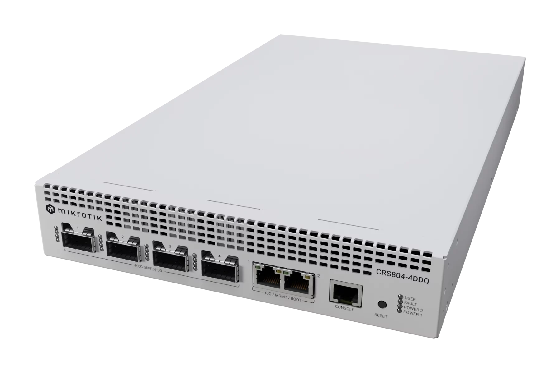
CRS804-4DDQ-hRM
A compact 1U 400G switch built for AI clusters, storage fabrics, and high-speed aggregation, featuring four 400G QSFP56-DD ports, dual 10 Gigabit Ethernet, and RouterOS v7.
Safety Warnings
Before you work on any equipment, be aware of the hazards involved with electrical circuitry, and be familiar with standard practices for preventing accidents.
Ultimate disposal of this product should be handled according to all national laws and regulations.
The Installation of the equipment must comply with local and national electrical codes.
This unit is intended to be installed in the rackmount. Please read the mounting instructions carefully before beginning installation. Failure to use the correct hardware or to follow the correct procedures could result in a hazardous situation to people and damage to the system.
This product is intended to be installed indoors. Keep this product away from water, fire, humidity or hot environments.
Use only the power supply and accessories approved by the manufacturer, and which can be found in the original packaging of this product.
The socket-outlet shall be installed near the equipment and shall be easily accessible.
Read the installation instructions before connecting the system to the power source.
We cannot guarantee that no accidents or damage will occur due to the improper use of the device. Please use this product with care and operate at your own risk!
In the case of device failure, please disconnect it from power. The fastest way to do so is by unplugging the power plug from the power outlet.
It is the customer's responsibility to follow local country regulations. All Mikrotik devices must be professionally installed.
This is a Class A product. In a domestic environment, this product might cause radio interference in which case the user might be required to take adequate measures
Quick start
- Connect with your PC to any Ethernet port;
- Connect the device to a power source;
- Configure the IP settings of your network card to 192.168.88.2/24;
- Use WebFig in a web browser or the "WinBox" configuration tool https://mt.lv/winbox; multiple configuration methods are available to ensure accessibility;
- Open http://192.168.88.1 in a web browser to start setup. If the IP address is unavailable, use WinBox and choose the "Neighbors" tab to find the device. Proceed to connect using the MAC address. The username is "admin", and there is no password (or, for some models, check user and wireless passwords on the sticker);
- For a manual update of the device, visit mikrotik.com, select your model, and locate the required packages in the "Downloads" section;
- Upload downloaded packages to the WebFig or WinBox "Files" menu and reboot the device;
- By upgrading your RouterOS software to the latest version, you can ensure optimal performance, stability, and security updates;
- Set up your router password.
Expansion slots and ports
- Product code: CRS804-4DDQ-hRM.
- CPU: Quad-Core AL52400 2000 MHz.
- CPU: architecture ARM 64bit.
- Size of RAM: 4 GB.
- RAM type: DDR4.
- Storage: 512 MB, NAND.
- Number of 10M/100M/1G/10G Ethernet ports: 2. Marked as MGMT/BOOT. It is possible to set Ether1 or Ether2 as the Etherboot port in System → RouterBOARD → Settings → Etherboot Port.
- Number of 400G QSFP56-DD ports: 4.
- PoE-out ports: Ether9-Ether16, 802.3af/at, Total output power 150 W.
- 1x RJ45 console port (set at 115200bits/s, 8 data bits, 1 stop bit no parity).
- Switch chip model: 98DX7335.
- Dimensions: 387 x 218 x 44 mm.
- Operating system RouterOS: v7, License level 6.
- Operating temperature: -10°C to +60°C.
- IP: 20
Please visit wiki pages for MikroTik SFP module compatibility and configuration table: https://help.mikrotik.com/docs/display/ROS/MikroTik+wired+interface+compatibility
LED indicators
- PWR1, PWR2 LEDs are lit when the router is powered with the PSU in use.
- USER LED indicates the device's state while powering it up into different modes, such as resetting the configuration or booting device for the Netinstall utility.
- FAULT LED indicates a problem with any of the cooling fans.
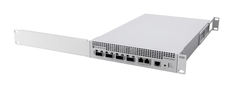
Mounting
The device is intended for indoor use and can be mounted in a 1U rackmount enclosure using the supplied rackmount accessories, or placed on a flat surface. For desktop installation, attach the supplied rubber feet to the bottom of the device. For rackmount installation, use a Phillips screwdriver to attach the rackmount ears to the device as described below.
Single device installation in a 1U rackmount enclosure

Attach the front rackmount bracket to one side of the device.
Attach the long rackmount bracket to the opposite side.
Attach the rear support ear to the device.
Secure all brackets using four screws, as shown in the illustration.
Place the device into the rackmount enclosure and align it with the mounting holes.
Tighten the rack screws to secure the device in place.
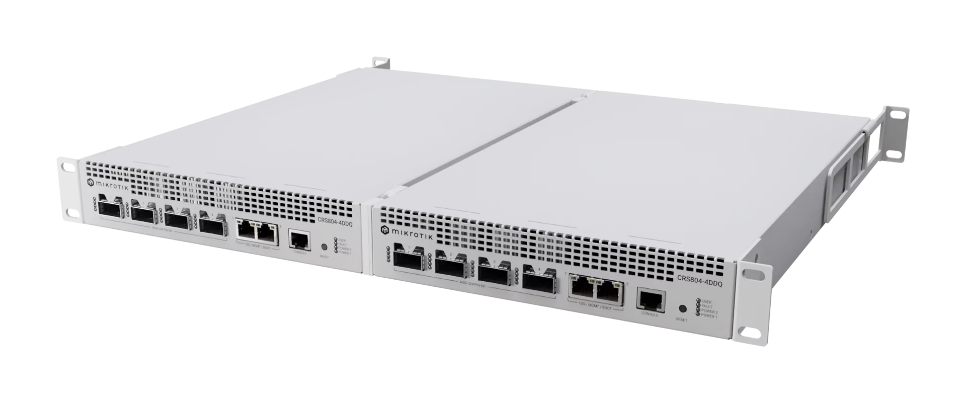
Installing two CRS804-4DDQ-hRM devices using RMK-2x10/19
Using the RMK-2x10/19 kit (included in the package), it is possible to mount two CRS804-4DDQ-hRM devices side by side within a single 1U rack unit.

Attach the front rackmount bracket and the rear support ear to the same (opposite) side of each device.
Secure each bracket using four screws, as shown in the illustration.
Attach the RMK-2x10/19 mounting parts to the remaining sides of both devices.
Secure the RMK-2x10/19 parts using four screws, as shown in the illustration.
Align and latch the two devices together according to the mounting guide.
Place the assembled unit into the rackmount enclosure and align it with the mounting holes.
Tighten the rack screws to secure the assembly in place.
The device is not protected against water exposure; please install it in a dry, well‑ventilated location.
We recommend using Cat 6 cables with our devices.
Mounting and configuring this device should be performed by a qualified professional.
Powering
The unit is equipped with two Hot Swap IEC type AC power supply G1394-0350WNA. AC input 100-240 V ⏦ (~ 50/60 Hz 8 A max). DC input 240V, 27,5A MAX +5VSB, 4A.
The maximum power consumption without attachments is 92 W, and under maximum load, it can reach 123W.
Configuration
Full documentation for RouterOS is available at: https://mt.lv/help.
You can configure the device using WebFig in a web browser or the "WinBox" configuration tool https://mt.lv/winbox; multiple configuration methods are available to ensure accessibility.
To start setup, open http://192.168.88.1 in a web browser to start setup. If the IP address is unavailable, use WinBox and choose the "Neighbors" tab to find the device. Proceed to connect using the MAC address. The username is "admin", and there is no password (or, for some models, check user and wireless passwords on the sticker).
The device is equipped with an RJ45 serial port, set by default to 115200 bit/s, 8 data bits, 1 stop bit, no parity. For recovery purposes, it is possible to reinstall the device from the network, see the Reset button.
Marvell Prestera switch chip features user manual
Cooling
The device is equipped with two New MT-HotSwapFan-V2 units.
Buttons
Reset button:
- Hold this button during boot time until the USR LED light starts flashing, release the button to reset RouterOS configuration.
- Hold the Reset button and power on your device (wait until the "USR" led is blinking then stable "On", and when the "USR" led is "Off" - release the Reset button) - the device is booting in bootp mode to reinstall RouterOS using Netinstall.
The MGMT/BOOT Ethernet port (Ether1 or Ether2) is used for the Netinstall process. See RouterOS documentation about using the Netinstall recovery utility.
Regardless of the above option used, the system will load the backup RouterBOOT loader if the button is pressed before power is applied to the device. Release the button before LED begins to flash, to only load backup RouterBOOT without resetting. This is useful for RouterBOOT debugging and recovery.
Accessories
Package includes the following accessories that come with the device:

Operating System Support
The device supports RouterOS software version 7 or above, as indicated in the RouterOS menu under /system resource. Other operating systems have not been tested.