Documentation
This document describes RouterOS, the operating system of MikroTik devices.
While the documentation is still being migrated, many additional articles are located in our old documentation portal..
|
Confluence Syndication Feed |
|||||||||||||||||||||||||||||||||||||||||||||||||||||||||||||||||||||||||||||||||||||||||||||||||||||||||||||||||||||
|---|---|---|---|---|---|---|---|---|---|---|---|---|---|---|---|---|---|---|---|---|---|---|---|---|---|---|---|---|---|---|---|---|---|---|---|---|---|---|---|---|---|---|---|---|---|---|---|---|---|---|---|---|---|---|---|---|---|---|---|---|---|---|---|---|---|---|---|---|---|---|---|---|---|---|---|---|---|---|---|---|---|---|---|---|---|---|---|---|---|---|---|---|---|---|---|---|---|---|---|---|---|---|---|---|---|---|---|---|---|---|---|---|---|---|---|---|---|
|
Kid Control
Page edited by Guntis G. SummarySub-menu: "Kid control" is a parental control feature to limit internet connectivity for LAN devices. Property DescriptionIn this menu, it is possible to create a profile for each Kid and restrict internet accessibility.
Time unlimited rate parameters have higher priority than rate-limit parameter. DevicesSub-menu: This sub-menu contains information if there are multiple connected devices to the internet (phone, tablet, gaming console, tv etc.). The device is identified by the MAC address that is retrieved from the ARP table. The appropriate IP address is taken from there.
Application exampleWith the following example we will restrict access for Peter's mobile phone:
[admin@MikroTik] > /ip kid-control add name=Peter mon="" tur-tue="00:00-24h" wed="" tur-thu="11:00-22:00" fri="" sat="18:30-22:00" tur-sun="15h-21h" rate-limit=3M
[admin@MikroTik] > /ip kid-control device add name=Mobile-phone user=Peter mac-address=FF:FF:FF:ED:83:63
Internet access limitation is implemented by adding dynamic firewall filter rules or simple queue rules. Here are example firewall filter rules: [admin@MikroTik] > /ip firewall filter print
1 D ;;; Mobile-phone, kid-control
chain=forward action=reject src-address=192.168.88.254
2 D ;;; Mobile-phone, kid-control
chain=forward action=reject dst-address=192.168.88.254 Dynamically created simple queue: [admin@MikroTik] > /queue simple print
Flags: X - disabled, I - invalid, D - dynamic
1 D ;;; Mobile-phone, kid-control
name="queue1" target=192.168.88.254/32 parent=none packet-marks="" priority=8/8 queue=default-small/default-small limit-at=3M/3M max-limit=3M/3M burst-limit=0/0
burst-threshold=0/0 burst-time=0s/0s bucket-size=0.1/0.1 It is possible to monitor how much data is used by the specific device: [admin@MikroTik] > /ip kid-control device print stats Flags: X - disabled, D - dynamic, B - blocked, L - limited, I - inactive # NAME IDLE-TIME RATE-DOWN RATE-UP BYTES-DOWN BYTES-UP 1 BI Mobile-phone 30s 0bps 0bps 3438.1KiB 8.9KiB It is also possible to pause Internet access for the created kids, it will restrict all access until resume is used, which will continue with configured settings: [admin@MikroTik] > /ip kid-control pause Peter [admin@MikroTik] > /ip kid-control print Flags: X - disabled, P - paused, B - blocked, L - rate-limited # NAME SUN MON TUE WED THU FRI SAT 0 PB Peter 15h-21h 11h-22h 18:30h-22h |
|||||||||||||||||||||||||||||||||||||||||||||||||||||||||||||||||||||||||||||||||||||||||||||||||||||||||||||||||||||
|
FlashFig
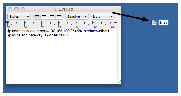
Page edited by Mārtiņš S. DescriptionFlashFig is an application for mass router configuration. It can be used by MikroTik distributors, ISPs, or any other companies who need to apply RouterOS configuration to many routers in the shortest possible time. FlashFig applies MikroTik RouterOS configuration to any RouterBOARD within 3 seconds. You can perform FlashFig on a batch of routers, the only thing you need is to connect RouterBOARD to a Layer 2 network running FlashFig and to power a FlashFig-enabled RouterBOARD up. FlashFig only runs on a Windows computer and is available from the downloads page. All RouterBOARDs support FlashFig mode. It works between a Windows computer running FlashFig and a RouterBOARD in the same broadcast domain (direct Layer 2 Ethernet network connection is required). FlashFig support is enabled on every new RouterBOARD manufactured since March 2010 by default from the factory. For older models, FlashFig can be enabled via RouterBOOT or from MikroTik RouterOS console - /system routerboard settings set boot-device=flash-boot-once-then-nand or /system routerboard settings set boot-device=flash-boot. FlashFig mode on a brand new RouterBOARD is disabled on further boots only after the first successful user login or successful FlashFig attempt to avoid unwanted reconfiguration at a later time. To use FlashFig a second time on the same router, you need to enable flash-boot in Bootloader settings (this setting will revert to NAND after a successful configuration change OR once any user logs into the board). If RouterOS reset-configuration command is used later (or configuration reset using the Reset button), FlashFig configuration is loaded. To permanently overwrite, use the Netinstall process and check Apply default configuration or use -r flag in Linux-based command line. You view FlashFig video tutorial on MikroTik YouTube channel. FlashFig ExampleThis is a step-by-step example of how to use the FlashFig process to apply a chosen MikroTik RouterOS configuration to a 'factory fresh' RouterBOARD. RequirementsThe Windows computer must be equipped with the following ports and contain the following files:
Be aware of the text editor's treatment of CR/LF characters and test that the config has no errors when normally applied onto an identical version of RouterOS before applying via FlashFig as run-time errors will not be visible! Pre-ConfigurationWindows Computer
RouterBOARD
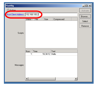
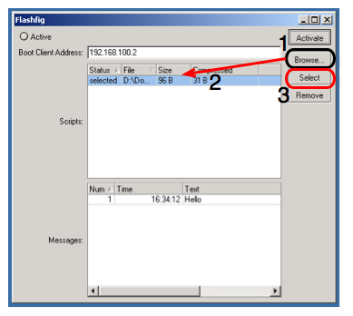
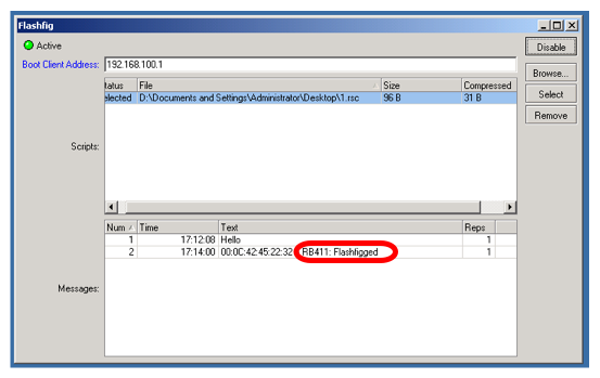
system/routerboard/settings/set boot-device=flash-boot Or use a more preferable option, for a single boot flash-boot: system/routerboard/settings/set boot-device=flash-boot-once-then-nand Your router is now ready for FlashFig. ConnectConnect the Boot port of RouterBOARD and FlashFig computer to the same Local Area Network. Run FlashFig
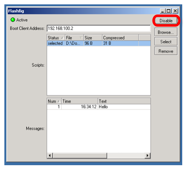
Messages log shows "FlashFigged" and RouterBOARD should repeatedly make the morse code sound for the character "/" ("_.._." and flash the LED - it is now safe to unplug / power down the router.
TroubleshootFlashFig can not find a routerIf between a PC and a router there is another device (a router/switch), ensure that for this device:
FlashFig finds a router, flashing is not done (no TFTP request)Ensure that the computer on which FlashFig is running has only one network interface active. FlashFig is done, but a configuration is not appliedIf all procedures went successfully, but RouterOS configuration from .rsc file is not applied, add startup delay to *.rsc configuration file. The reason might be, that the configuration script is executed before all interfaces boots up. Not enough flash space, ignoringFlashFig configuration maximum file size is up to 4000 bytes, otherwise program will return an error as above. |
|||||||||||||||||||||||||||||||||||||||||||||||||||||||||||||||||||||||||||||||||||||||||||||||||||||||||||||||||||||
|
LTE
Page edited by Emīls T.
|
| Property | Description |
|---|---|
| allow-roaming (yes | no; Default: no) | Enable data roaming for connecting to other countries' data-providers. Not all LTE modems support this feature. Some modems, that do not fully support this feature, will connect to the network but will not establish an IP data connection with allow-roaming set to no. |
| apn-profiles (string; Default: default) | Which APN profile to use for this interface |
| band (integer list; Default: "") | LTE Frequency band used in communication LTE Bands and bandwidths |
| nr-band (integer list; Default: "") | 5G NR Frequency band used in communication 5G NR Bands and bandwidths |
| comment (string; Default: "") | Descriptive name of an item |
| disabled (yes | no; Default: yes) | Whether the interface is disabled or not. By default it is disabled. |
| modem-init (string; Default: "") | Modem init string (AT command that will be executed at modem startup) |
| mtu (integer; Default: 1500) | Maximum Transmission Unit. Max packet size that the LTE interface will be able to send without packet fragmentation. |
| name (string; Default: "") | Descriptive name of the interface. |
| network-mode (3g | gsm | lte | 5g) | Select/force mode for LTE interface to operate with |
| operator (integer; Default: "") | used to lock the device to a specific operator full PLMN number is used for the lock consisting of MCC+MNC. PLMN codes |
| pin (integer; Default: "") | SIM Card's PIN code. |
APN profiles
All network-related settings are under profiles
Sub-menu: /interface lte apn
| Property | Description |
|---|---|
| add-default-route (yes | no) | Whether to add a default route to forward all traffic over the LTE interface. |
| apn (string) | Service Provider's Access Point Name |
| authentication (pap | chap | none; Default: none) | Allowed protocol to use for authentication |
| default-route-distance (integer; Default: 2) | Sets distance value applied to auto-created default route, if add-default-route is also selected. LTE route by default is with distance 2 to prefer wired routes over LTE |
| ip-type (ipv4 | ipv4-ipv6 | ipv6; Default: ) | Requested PDN type |
| ipv6-interface (; Default: ) | Interface on which to advertise IPv6 prefix |
| name (string; Default: ) | APN profile name |
| number (integer; Default: ) | APN profile number |
| passthrough-interface (; Default: ) | Interface to passthrough IP configuration (activates passthrough) |
| passthrough-mac (MAC; Default: auto) | If set to auto, then will learn MAC from the first packet |
| passthrough-subnet-selection (auto / p2p; Default: auto) | "auto" selects the smallest possible subnet to be used for the passthrough interface. "p2p" sets the passthrough interface subnet as /32 and picks gateway address from 10.177.0.0/16 range. The gateway address stays the same until the apn configuration is changed. |
| password (string; Default: ) | Password used if any of the authentication protocols are active |
| use-network-apn (yes | no; Default: yes) | Parameter is available starting from RouterOS v7 and used only for MBIM modems. If set to yes, uses network provided APN. |
| use-peer-dns (yes | no; Default: yes) | If set to yes, uses DNS received from LTE interface |
| user (integer) | Username used if any of the authentication protocols are active |
LTE settings
LTE and router-specific LTE settings. The menu is available starting from RouterOS v7.
Sub-menu: /interface lte settings
| Property | Description |
|---|---|
| mode (auto | mbim | serial / user; Default: auto) | Operation mode setting.
|
| firmware-path (string) | Firmware path in host OS. Modem gobi firmware |
| external-antenna (auto | both | div | main | none; Default: auto) | This setting is only available for "Chateau" routers, except for Chateau 5G versions.
|
| external-antenna-selected () | This setting is only available for "Chateau" routers, except for Chateau 5G versions. Shows the currently selected antenna if "external-antenna" is set to "auto" |
| sim-slot () | This setting is available for routers that have switchable SIM slots (LtAP, SXT). Selection options differ between products. |
Scanner
It is possible to scan LTE interfaces with /interface lte scan command. Example:
[admin@MikroTik] > /interface lte scan duration=60 number=0
Columns: OPERATOR, MCC-MNC, RSSI, RSRP, RSRQ
OPERATOR  MCC-MNC  RSSI    RSRP    RSRQ
LMT         24701  -36dBm  -63dBm  -7dB
Available properties:
| Property | Description |
|---|---|
| duration (integer) | Duration of scan in seconds |
| freeze-frame-interval (integer) | time between data printout |
| number (integer) | Interface number or name |
User Info command
It is possible to send a special "info" command to LTE interface with /interface lte info command. In RouterOS v7 this command is moved to /interface lte monitor menu.
Properties (Up to 6.40)
| Property | Description |
|---|---|
| user-command (string; Default: "") | send a command to the LTE card to extract useful information, e.g. with AT commands |
| user-command-only (yes | no; Default: ) |
User at-chat command
It is possible to send user defined "at-chat" command to the LTE interface with /interface lte at-chat command.
[admin@MikroTik] > /interface lte at-chat lte1 input="AT"
  output: OK
It is also possible to use the "wait" parameter wait=yes with the command to make "at-chat" wait for 5 seconds and return all the output instead of returning only the first received data, this is useful for some commands that return multiline output or a large block of data.
[admin@MikroTik] > interface lte at-chat lte1 input="at+qcfg=?"
  output:

[admin@MikroTik] > interface lte at-chat lte1 input="at+qcfg=?" wait=yes
  output: +QCFG: "rrc",(0-5)
          +QCFG: "hsdpacat",(6,8,10-24)
          +QCFG: "hsupacat",(5,6)
          +QCFG: "pdp/duplicatechk",(0,1)
          +QCFG: "risignaltype",("respective","physical")
          +QCFG: "lte/bandprior",(1-43),(1-43),(1-43)
          +QCFG: "volte_disable",(0,1)
          +QCFG: "diversity/config",(4,6),(1-4),(0)
          +QCFG: "div_test_mode",(0,1)
          +QCFG: "usbspeed",("20","30")
          +QCFG: "data_interface",(0,1),(0,1)
          +QCFG: "pcie/mode",(0,1)
          +QCFG: "pcie_mbim",(0,1)
          +QCFG: "sms_control",(0,1),(0,1)
          +QCFG: "call_control",(0,1),(0,1)
          +QCFG: "usb/maxpower",(0-900)
          +QCFG: "efratctl",(0,1)
          +QCFG: "netmaskset",(0,1)[,<netmask>]
          +QCFG: "mmwave",ant_chip,ant_type
          +QCFG: "gatewayset",(0,1)[,<gateway>]
          +QCFG: "clat",(0,1),(0,1),<prefix>,(0,32,40,48,56,64,96),<fqdn>,(0,1),(0,1,2,4,8),(0,1),(0,1),(0,1,2),(0,1,2)
          +QCFG: "usage/apmem"
          +QCFG: "enable_gea1"[,(0,1)]
          +QCFG: "dhcppktfltr",(0,1)
          OK
You can also use "at-chat" function in scripts and assign command output to variable.
[admin@MikroTik] > :global "lte_command" [/interface lte at-chat lte1 input="AT+CEREG?" as-value ]
[admin@MikroTik] > :put $"lte_command"
output=+CEREG: 0,1
OK
Quick setup example
Start with network settings - Add new connection parameters under LTE apn profile (provided by network provider):
/interface lte apn add name=profile1 apn=phoneprovider.net authentication=chap password=web user=web
Select the newly created profile for an LTE connection:
/interface lte set [find] apn-profiles=profile1
LTE interface should appear with the running (R) flag:
[admin@MikroTik] > /interface lte print
Flags: X - disabled, R - running
0 R name="lte1" mtu=1500 mac-address=AA:AA:AA:AA:AA:AA
If required, add NAT Masquerade for LTE Interface to get internet to the local network:
/ip firewall nat add action=masquerade chain=srcnat out-interface=lte1
After the interface is added, you can use the "info" command to see what parameters the client acquired (parameters returned depends on the LTE hardware device):
[admin@MikroTik] > interface/lte/monitor lte1
            status: connected
             model: EG18-EA
          revision: EG18EAPAR01A12M4G
  current-operator: LMT
    current-cellid: 3103242
            enb-id: 12122
         sector-id: 10
        phy-cellid: 480
        data-class: LTE
    session-uptime: 15m54s
              imei: 86981604098XXXX
              imsi: 24701060267XXXX
              uicc: 8937101122102057XXXX
      primary-band: B3@20Mhz earfcn: 1300 phy-cellid: 480
     dl-modulation: qpsk
               cqi: 7
                ri: 2
               mcs: 1
              rssi: -68dBm
              rsrp: -97dBm
              rsrq: -9dB
              sinr: 6dB
Passthrough Example
Some LTE interfaces support the LTE Passthrough feature where the IP configuration is applied directly to the client device. In this case, modem firmware is responsible for the IP configuration, and the router is used only to configure modem settings - APN, Network Technologies, and IP-Type. In this configuration, the router will not get IP configuration from the modem. The LTE Passthrough modem can pass both IPv4 and IPv6 addresses if that is supported by the modem. Some modems support multiple APNs where you can pass the traffic from each APN to a specific router interface.
Passthrough will only work for one host. The router will automatically detect the MAC address of the first received packet and use it for the Passthrough. If there are multiple hosts on the network it is possible to lock the Passthrough to a specific MAC. On the host on the network where the Passthrough is providing the IP a DHCP-Client should be enabled on that interface too. Note, that it will not be possible to connect to the LTE router via a public lte IP address or from the host which is used by the passthrough. It is suggested to create an additional connection from the LTE router to the host for configuration purposes. For example vlan interface between the LTE router and host.
To enable the Passthrough a new entry is required or the default entry should be changed in the '/interface lte apn' menu
Examples.
To configure the Passthrough on ether1:
[admin@MikroTik] > /interface lte apn add apn=apn1 passthrough-interface=ether1
[admin@MikroTik] > /interface lte set lte1 apn-profiles=apn1
To configure the Passthrough on ether1 host 00:0C:42:03:06:AB:
[admin@MikroTik] > /interface lte apn add apn=apn1 passthrough-interface=ether1 passthrough-mac=00:0C:42:03:06:AB
[admin@MikroTik] > /interface lte set lte1 apn-profiles=apn1
To configure multiple APNs on ether1 and ether2:
[admin@MikroTik] > /interface lte apn add apn=apn1 passthrough-interface=ether1
[admin@MikroTik] > /interface lte apn add apn=apn2 passthrough-interface=ether2
[admin@MikroTik] > /interface lte set lte1 apn-profiles=apn1,apn2
To configure multiple APNs with the same APN for different interfaces:
[admin@MikroTik] > /interface lte apn add name=interface1 apn=apn1
[admin@MikroTik] > /interface lte apn add name=interface2 apn=apn1 passthrough-interface=ether1
[admin@MikroTik] > /interface lte set lte1 apn-profiles=interface1
[admin@MikroTik] > /interface lte set lte2 apn-profiles=interface2
Dual SIM
Boards with switchable SIM slots
| RouterBoard | Modem slot | SIM slots | Switchable |
|---|---|---|---|
| LtAP | lower | 2 | 3 | Y |
| upper | 1 | N | |
| LtAP mini | up | down | Y | |
| SXT R | a | b | Y |
SIM slots switching commands
- RouterOS v7
/interface lte settings set sim-slot=down
- RouterOS v6 after 6.45.1
/system routerboard modem set sim-slot=down
- RouterOS v6 pre 6.45.1:
/system routerboard sim set sim-slot=down
For more reference please see the board block diagram, Quick Guide, and User manual.
Usage Example
Follow this link - Dual SIM Application, to see examples of how to change SIM slot based on roaming status and in case the interface status is down, with the help of RouterOS scripts and scheduler.
Tips and Tricks
This paragraph contains information for additional features and usage cases.
Find device location using Cell information
On devices using the R11e-LTE International version card (wAP LTE kit) some extra information is provided under info command.
   current-operator: 24701
                lac: 40
current-cellid: 2514442| Property | Description |
|---|---|
| current-operator (integer; Default: ) | Contains MCC and MNC. For example: current-operator: 24701 breaks to: MCC=247 MNC=01 |
| lac (integer; Default: ) | location area code (LAC) |
| current-cellid (integer; Default: ) | Station identification number |
Values can be used to find location in databases: Cell Id Finder
Using Cell lock
It is possible to lock R11e-LTE, R11e-LTE6 and R11e-4G modems and equipped devices to the exact LTE tower. LTE info command provides currently used cellular tower information:
         phy-cellid: 384
earfcn: 1300 (band 3, bandwidth 20Mhz)| Property | Description |
|---|---|
| phy-cellid (integer; Default: ) | Physical Cell Identification (PCI) of currently used cell tower. |
| earfcn (integer; Default: ) | Absolute Radio Frequency Channel Number |
Exact tower location as well as available bands and other information can be acquired from mobile carrier or by using online services:
By using those acquired variables it's possible to send the AT command to modem for locking to tower in the current format:
for R11e-LTE and R11e-LTE6
AT*Cell=<mode>,<NetworkMode>,<band>,<EARFCN>,<PCI>

where

<mode> :
0 – Cell/Frequency disabled
1 – Frequency lock enabled
2 – Cell lock enabled

<NetworkMode>
0 – GSM
1 – UMTS_TD
2 – UMTS_WB
3 – LTE

<band>
Not in use, leave this blank

<EARFCN>
earfcn from lte info

<PCI>
phy-cellid from lte info
To lock modem at previously used tower at-chat can be used:
/interface lte at-chat lte1 input="AT*Cell=2,3,,1300,384"
For R11e-LTE all set on locks are lost after reboot or modem reset. Cell data can be also gathered from "cell-monitor".
For R11e-LTE6 cell lock works only for the primary band, this can be useful if you have multiple channels on the same band and you want to lock it to a specific earfcn. Note, that cell lock is not band-specific and for ca-band it can also use other frequency bands, unless you use band lock.
Use cell lock to set the primary band to the 1300 earfcn and use the second channel for the ca-band:
/interface lte at-chat lte1 input="AT*Cell=2,3,,1300,138"
Now it uses the earfcn: 1300 for the primary channel:
         primary-band: B3@20Mhz earfcn: 1300 phy-cellid: 138
              ca-band: B3@5Mhz earfcn: 1417 phy-cellid: 138
You can also set it the other way around:
/interface lte at-chat lte1 input="AT*Cell=2,3,,1417,138"
Now it uses the earfcn: 1417 for the primary channel:
         primary-band: B3@5Mhz earfcn: 1417 phy-cellid: 138
              ca-band: B3@20Mhz earfcn: 1300 phy-cellid: 138
For R11e-LTE6 modem cell lock information will not be lost after reboot or modem reset. To remove cell lock use at-chat command:
/interface lte at-chat lte1 input="AT*Cell=0"
for R11e-4G
AT%CLCMD=<mode>,<mode2>,<EARFCN>,<PCI>,<PLMN>
AT%CLCMD=1,1,3250,244,\"24705\"

where

<mode> :
0 – Cell/Frequency disabled
1 – Cell lock enabled

<mode2> :
0 - Save lock for first scan
1 - Always use lock
(after each reset modem will clear out previous settings no matter what is used here)

<EARFCN>
earfcn from lte info

<PCI>
phy-cellid from lte info

<PLMN>
Mobile operator code
All PLMN codes available here this variable can be also left blank
To lock the modem to the cell - modem needs to be in non operating state, the easiest way for R11e-4G modem is to add CellLock line to "modem-init" string:
/interface lte set lte1 modem-init="AT%CLCMD=1,1,3250,244,\"24705\""
Multiple cells can also be added by providing a list instead of one tower information in the following format:
AT%CLCMD=<mode>,<mode2>,<EARFCN_1>,<PCI_1>,<PLMN_1>,<EARFCN_2>,<PCI_2>,<PLMN_2>
For example to lock to two different PCIs within the same band and operator:
/interface lte set lte1 modem-init="AT%CLCMD=1,1,6300,384,\"24701\",6300,385,\"24701\""
for Chateau LTE12, Chateau 5G, LHG LTE18 and ATL LTE18
AT+QNWLOCK="common/4g",<num of cells>,[[<freq>,<pci>],...]
AT+QNWLOCK=\"common/4g\",1,6300,384

where

<num of cells>
number of cells to cell lock

<freq>
earfcn from lte info

<pci>
phy-cellid from lte info
Single-cell lock example:
/interface lte at-chat lte1 input="AT+QNWLOCK=\"common/4g\",1,3050,448"
Query current configuration:
/interface lte at-chat lte1 input="AT+QNWLOCK=\"common/4g\""
Multiple cells can also be added to the cell lock. For example to lock to two different cells:
/interface lte at-chat lte1 input="AT+QNWLOCK=\"common/4g\",2,3050,448,1574,474"
To remove the cell lock use this at-chat command:
/interface lte at-chat lte1 input="at+qnwlock=\"common/4g\",0"
for Chateau LTE6
AT+GTCELLLOCK=<mode>[,<rat>,<type>,<earfcn>[,<PCI>]]

where

< mode >: integer type; 0 Disable this function 1 Enable this function 2 Add new cell to be locked

<rat>: integer type; 0 LTE 1 WCDMA

<type>: integer type; 0 Lock PCI 1 Lock frequency

<earfcn>: integer type; the range is 0-65535.

<PCI>: integer type; If second parameter value is 0, the range is 0-503 for LTE If second parameter value is 1, the rang is 0-512 for WCDMA
Example:
/interface lte at-chat lte1 input="AT+GTCELLLOCK=1,0,0,6175,176"
Cell Monitor
Cell monitor allows to scan available nearby mobile network cells:
[admin@MikroTik] > /interface lte cell-monitor lte1
PHY-CELLID BAND         PSC EARFCN                 RSRP          RSRQ          RSSI         SINR
        49 B20              6300                -110dBm       -19.5dB
       272 B20              6300                -116dBm       -19.5dB
       374 B20              6300                -108dBm         -16dB
       384 B1               150                 -105dBm       -13.5dB
       384 B3               1300                -106dBm         -12dB
       384 B7               2850                -107dBm       -11.5dB
       432 B7               2850                -119dBm       -19.5dB
Gathered data can be used for more precise location detection or for Cell lock.
Troubleshooting
Enable LTE logging:
[admin@MikroTik] > /system logging add topics=lte
Check for errors in log:
[admin@MikroTik] > /log print

11:08:59 lte,async lte1: sent AT+CPIN?
11:08:59 lte,async lte1: rcvd +CME ERROR: 10
search for CME error description online,
in this case: CME error 10 - SIM not inserted
Locking band on Huawei and other modems
To lock band for Huawei modems /interface lte set lte1 band="" option can't be used.
It is possible to use AT commands to lock to the desired band manually.
To check all supported bands run the at-chat command:
[admin@MikroTik] /interface lte at-chat lte1 input="AT^SYSCFGEX=\?"

output: ^SYSCFGEX: ("00","03","02","01","99"),((2000004e80380,"GSM850/GSM900/GSM1800/GSM1900/WCDMA BCI/WCDMA BCII/WCDMA BCV/WCDMA BCVIII"),
(3fffffff,"All Bands")),(0-2),(0-4),((800d7,"LTE BC1/LTE BC2/LTE
BC3/LTE BC5/LTE BC7/LTE BC8/LTE BC20"),(7fffffffffffffff,"All Bands"))
OK
Example to lock to LTE band 7:
[admin@MikroTik] /interface lte set lte1 modem-init="AT^SYSCFGEX=\"03\",3FFFFFFF,2,4,40,,"
Change last part 40 to desired band specified hexadecimal value where:
4 LTE BC3
40 LTE BC7
80000 LTE BC20
7FFFFFFFFFFFFFFF  All bands
etc
All band HEX values and AT commands can be found in Huawei AT Command Interface Specification guide
Check if the band is locked:
[admin@MikroTik] /interface lte at-chat lte1 input="AT^SYSCFGEX\?"

output: ^SYSCFGEX: "03",3FFFFFFF,0,2,40
OK
For more information check modem manufacturers AT command reference manuals.
mPCIe modems with RB9xx series devices
In case your modem is not being recognized after a soft reboot, then you might need to add a delay before the USB port is initialized. This can be done using the following command:
/system routerboard settings set init-delay=5s
Boards with USB-A port and mPCIe
Some devices such as specific RB9xx's and the RBLtAP-2HnD share the same USB lines between a single mPCIe slot and a USB-A port. If auto switch is not taking place and a modem is not getting detected, you might need to switch manually to either use the USB-A or mini-PCIe:
/system routerboard usb set type=mini-PCIe
Modem firmware upgrade
It is possible to upgrade modems firmware. The firmware upgrade is also possible for the Chateau series products starting from the 7.1beta1 version.
Firmware update is available only as FOTA Firmware Over The Air - firmware upgrade can only be done through a working mobile connection for:
- )R11e-LTE
- )R11e-LTE-US
Firmware update available as FOTA and as well as upgrade from file for:
- )R11e-4G
- )R11e-LTE6
Firmware update available as FOTA with access to the internet over any interface:
- )EG12-EA (Chateau LTE12)
- )RG502Q-EA (Chateau 5G)
- )EG18-EA (LHG LTE18)
Firmware updates usually include stability improvements or small bug fixes that can't be included in RouterOS.
Check the currently used firmware version by running:
[admin@MikroTik] > /interface lte info lte1 once

-----
revision: "MikroTik_CP_2.160.000_v008"
-----
Check if new firmware is available:
[admin@MikroTik] > /interface lte firmware-upgrade lte1
  installed: MikroTik_CP_2.160.000_v008
     latest: MikroTik_CP_2.160.000_v010
Upgrade firmware:
[admin@MikroTik] > /interface lte firmware-upgrade lte1 upgrade=yes
  status: downloading via LTE connection (>2min)
After a successful upgrade issue USB power-reset, reboot device or run AT+reset command, to update the modem version readout under info command:
[admin@MikroTik] > /interface lte at-chat lte1 input="AT+reset"
if modem has issues connecting to cells after update, or there are any other unrelated issues - wipe old configuration with:
/interface lte at-chat lte1 input="AT+RSTSET"
Avoiding tethering speed throttling
Some operators (TMobile, YOTA etc.) allow unlimited data only for the device the SIM card is used on, all other data coming from mobile hotspots or tethering is highly limited by volume or by throughput speed. Some sources have found out that this limitation is done by monitoring TTL (Time To Live) values from packets to determine if limitations need to be applied (TTL is decreased by 1 for each "hop" made). RouterOS allows changing the TTL parameter for packets going from the router to allow hiding sub networks. Keep in mind that this may conflict with fair use policy.
IPv4 mangle rule:
/ip firewall mangle
add action=change-ttl chain=postrouting new-ttl=set:65 out-interface=lte1 passthrough=yes
IPv6 mangle rule:
/ipv6 firewall mangle
add action=change-hop-limit chain=postrouting new-hop-limit=set:65 passthrough=yes
More information: YOTA, TMobile
Unlocking SIM card after multiple wrong PIN code attempts
After locking the SIM card, unlock can be done through "at-chat"
Check current PIN code status:
/interface lte at-chat lte1 input="at+cpin\?"
If card is locked - unlock it by providing:
/interface lte at-chat lte1 input="AT+CPIN=\"PUK_code\",\"NEW_PIN\""
Replace PUK_code and NEW_PIN with matching values.
The command for sim slot selection changes in v6.45.1 and again in v7. Some device models like SXT, have SIM slots named "a" and "b" instead of "up" and down"
Page edited by Māris B. - "Add back Static inter-VRF routes example"
- Description
- Configuration
- Supported features
- VRF interfaces in firewall
- Examples
- References
Description
RouterOS allows to create multiple Virtual Routing and Forwarding instances on a single router. This is useful for BGP-based MPLS VPNs. Unlike BGP VPLS, which is OSI Layer 2 technology, BGP VRF VPNs work in Layer 3 and as such exchange IP prefixes between routers. VRFs solve the problem of overlapping IP prefixes and provide the required privacy (via separated routing for different VPNs).
It is possible to set up vrf-lite setups or use multi-protocol BGP with VPNv4 address family to distribute routes from VRF routing tables - not only to other routers, but also to different routing tables in the router itself.
Configuration
VRF table is created in /ip vrf menu. After the VRF config is created routing table mapping is added (a dynamic table with the same name is created). Each active VRF will always have a mapped routing table.
[admin@arm-bgp] /ip/vrf> print
Flags: X - disabled; * - builtin
 0  * name="main" interfaces=all

[admin@arm-bgp] /routing/table> print
Flags: D - dynamic; X - disabled, I - invalid; U - used
 0 D   name="main" fib
Note that the order of the added VRFs is significant. To properly match which interface will belong to the VRF care must be taken to place VRFs in the correct order (matching is done starting from the top entry, just like firewall rules).
Since each VRF has mapped routing table, count of max unique VRFs is also limited to 4096.
Let's look at the following example:
[admin@arm-bgp] /ip/vrf> print
Flags: X - disabled; * - builtin
 0  * name="main" interfaces=all
 1    name="myVrf" interfaces=lo_vrf
Since the first entry is matching all the interfaces, the second VRF will not have any interfaces added. To fix the problem order of the entries must be changed.
[admin@arm-bgp] /ip/vrf> move 1 0
[admin@arm-bgp] /ip/vrf> print
Flags: X - disabled; * - builtin
 0    name="myVrf" interfaces=lo_vrf
 1  * name="main" interfaces=all
Connected routes from the interfaces assigned to the VRF will be installed in the right routing table automatically.
When the interface is assigned to the VRF as well as connected routes it does not mean that RouterOS services will magically know which VRF to use just by specifying the IP address in the configuration. Each service needs VRF support to be added and explicit configuration. Whether the service has VRF support and has VRF configuration options refer to appropriate service documentation.
For example, let's make an SSH service to listen for connections on the interfaces belonging to the VRF:
[admin@arm-bgp] /ip/service> set ssh vrf=myVrf
[admin@arm-bgp] /ip/service> print
Flags: X, I - INVALID
Columns: NAME, PORT, CERTIFICATE, VRF
#   NAME     PORT  CERTIFICATE  VRF
0   telnet     23               main
1   ftp        21
2   www        80               main
3   ssh        22               myVrf
4 X www-ssl   443  none         main
5   api      8728               main
6   winbox   8291               main
7   api-ssl  8729  none         main
Adding routes to the VRF is as simple as specifying the routing-table parameter when adding the route and specifying in which routing table to resolve the gateway by specifying @name after the gateway IP:
/ip route add dst-address=192.168.1.0/24 gateway=172.16.1.1@myVrf routing-table=myVrf
Traffic leaking between VRFs is possible if the gateway is explicitly set to be resolved in another VRF, for example:
# add route in the myVrf, but resolve the gateway in the main table
/ip route add dst-address=192.168.1.0/24 gateway=172.16.1.1@main routing-table=myVrf

# add route in the main table, but resolve the gateway in the myVrf
/ip route add dst-address=192.168.1.0/24 gateway=172.16.1.1@myVrf
If the gateway configuration does not have an explicitly configured table to be resolved in, then it is considered, that gateway should be resolved in the "main" table.
Supported features
Different services can be placed in specific VRF on which the service is listening for incoming or creating outgoing connections. By default, all services are using the main table, but it can be changed with a separate vrf parameter or by specifying the VRF name separated by "@" at the end of the IP address.
Below is the list of supported services.
Feature | Support | Comment |
|---|---|---|
| BGP | + | /routing bgp template add name=bgp-template1 vrf=vrf1 /routing bgp vpls add name=bgp-vpls1 site-id=10 vrf=vrf1 /routing bgp vpn add label-allocation-policy=per-vrf vrf=vrf1 |
| + | /tool e-mail set address=192.168.88.1 vrf=vrf1 | |
| IP Services | + | VRF is supported for /ip service set telnet vrf=vrf1 |
| L2TP Client | + | /interface l2tp-client add connect-to=192.168.88.1@vrf1 name=l2tp-out1 user=l2tp-client |
| MPLS | + | /mpls ldp add vrf=vrf1 |
| Netwatch | + | /tool netwatch add host=192.168.88.1@vrf1 |
| NTP | + | /system ntp client set vrf=vrf1 /system ntp server set vrf=vrf1 |
| OSPF | + | /routing ospf instance add disabled=no name=ospf-instance-1 vrf=vrf1 |
| ping | + | /ping 192.168.88.1 vrf=vrf1 |
| RADIUS | + | /radius add address=192.168.88.1@vrf1 /radius incoming set vrf=vrf1 |
| RIP | + | /routing rip instance add name=rip-instance-1 vrf=vrf1 |
| RPKI | + | /routing rpki add vrf=vrf1 |
| SNMP | + | /snmp set vrf=vrf1 |
| EoIP | + | /interface eoip add remote-address=192.168.1.1@vrf1 |
| IPIP | + | /interface ipip add remote-address=192.168.1.1@vrf1 |
| GRE | + | /interface gre add remote-address=192.168.1.1@vrf1 |
| SSTP-client | + | /interface sstp-client add connect-to=192.168.1.1@vrf1 |
| OVPN-client | + | /interface ovpn-client add connect-to=192.168.1.1@vrf1 |
| L2TP-ether | + | /interface l2tp-ether add connect-to=192.168.2.2@vrf |
| VXLAN | + | /interface vxlan add vni=10 vrf=vrf1 |
| Fetch | + | /tool/fetch address=10.155.28.236@vrf1 mode=ftp src-path=my_file.pcap user=admin password="" |
| DNS | + Starting from RouterOS v7.15 | /ip dns set vrf=vrf1 |
| DHCP-Relay | + Starting from RouterOS v7.15 | /ip dhcp-relay set dhcp-server-vrf=vrf1 |
VRF interfaces in firewall
Before RouterOS version 7.14, firewall filter rules with the property in/out-interface would apply to interfaces within a VRF instance. Starting from RouterOS version 7.14, these rules no longer target individual interfaces within a VRF, but rather the VRF interface as a whole.
Started from version 7.14 when interfaces are added in VRF - virtual VRF interface is created automatically. If it is needed to match traffic which belongs to VRF interface, VRF virtual interface should be used in firewall filters, for example:
/ip vrf add interfaces=ether5 name=vrf5
/ip firewall filter add chain=input in-interface=vrf5 action=accept
If there are several interfaces in one VRF but it is needed to match only one of these interfaces - marks should be used. For example:
/ip vrf add interface=ether15,ether16 vrf=vrf1516
/ip firewall mangle
add action=mark-connection chain=prerouting connection-state=new in-interface=ether15 new-connection-mark=input_allow passthrough=yes
/ip firewall filter
add action=accept chain=input connection-mark=input_allow
Examples
Simple VRF-Lite setup
Let's consider a setup where we need two customer VRFs that require access to the internet:
/ip address
add address=172.16.1.2/24 interface=public
add address=192.168.1.1/24 interface=ether1
add address=192.168.2.1/24 interface=ether2

/ip route
add gateway=172.16.1.1

# add VRF configuration
/ip vrf
add name=cust_a interface=ether1 place-before 0
add name=cust_b interface=ether2 place-before 0

# add vrf routes
/ip route
add gateway=172.16.1.1@main routing-table=cust_a
add gateway=172.16.1.1@main routing-table=cust_b

# masquerade local source
/ip firewall nat add chain=srcnat out-interface=public action=masquerade
It might be necessary to ensure that packets coming in the "public" interface can actually reach the correct VRF.
This can be solved by marking new connections originated by the VRF customers and steering the traffic by routing marks of incoming packets on the "public" interface.
# mark new customer connections
/ip firewall mangle
add action=mark-connection chain=prerouting connection-state=new new-connection-mark=\
    cust_a_conn src-address=192.168.1.0/24 passthrough=no
add action=mark-connection chain=prerouting connection-state=new new-connection-mark=\
    cust_b_conn src-address=192.168.2.0/24 passthrough=no

# mark routing
/ip firewall mangle
add action=mark-routing chain=prerouting connection-mark=cust_a_conn \
    in-interface=public new-routing-mark=cust_a
add action=mark-routing chain=prerouting connection-mark=cust_b_conn \
    in-interface=public new-routing-mark=cust_b
Static inter-VRF routes
In general, it is recommended that all routes between VRF should be exchanged using BGP local import and export functionality. If that is not enough, static routes can be used to achieve this so-called route leaking.
There are two ways to install a route that has a gateway in a different routing table than the route itself.
The first way is to explicitly specify the routing table in the gateway field when adding a route. This is only possible when leaking a route and gateway from the "main" routing table to a different routing table (VRF). Example:
# add route to 5.5.5.0/24 in 'vrf1' routing table with gateway in the main routing table
add dst-address=5.5.5.0/24 gateway=10.3.0.1@main routing-table=vrf1
The second way is to explicitly specify the interface in the gateway field. The interface specified can belong to a VRF instance. Example:
# add route to 5.5.5.0/24 in the main routing table with gateway at 'ether2' VRF interface
add dst-address=5.5.5.0/24 gateway=10.3.0.1%ether2 routing-table=main
# add route to 5.5.5.0/24 in the main routing table with 'ptp-link-1' VRF interface as gateway
add dst-address=5.5.5.0/24 gateway=ptp-link-1 routing-table=main
As can be observed, there are two variations possible - to specify gateway as ip_address%interface or to simply specify an interface. The first should be used for broadcast interfaces in most cases. The second should be used for point-to-point interfaces, and also for broadcast interfaces, if the route is a connected route in some VRF. For example, if you have an address 1.2.3.4/24 on interface ether2 that is put in a VRF, there will be a connected route to 1.2.3.0/24 in that VRF's routing table. It is acceptable to add a static route 1.2.3.0/24 in a different routing table with an interface-only gateway, even though ether2 is a broadcast interface:
add dst-address=1.2.3.0/24 gateway=ether2 routing-table=main
Static VRF-Lite Connected route leaking
Sometimes it is necessary to access directly connected resources from another vrf. In our example setup we have two connected networks each in its own VRF. And we want to allow client1 to be able to access client2.
                   +-----------------+
                   |+-vrf1-+ +-vrf2-+|
client1(*.2)-------||ip *.1| |ip *.1||-------client2(*.2)
   (10.11.0.0/24)  |+------+ +------+|   (10.12.0.0/24)
                   +-----------------+
/ip address add address=10.11.0.1/24 interface=sfp-sfpplus1 add address=10.12.0.1/24 interface=sfp-sfpplus2 # add VRF configuration /ip vrf add name=vrfTest1 interface=sfp-sfpplus1 place-before 0 add name=vrfTest2 interface=sfp-sfpplus2 place-before 0
We can say that connected network is reachable on specific vrf by setting gateway "interface@vrf"
# add vrf routes /ip route add dst-address=10.11.0.0/24 gateway="sfp-sfpplus1@vrfTest1" routing-table=vrfTest2 add dst-address=10.12.0.0/24 gateway="sfp-sfpplus2@vrfTest2" routing-table=vrfTest1
Verify routes and reachability:
[admin@CCR2004_2XS] /ip/route> print detail
Flags: D - dynamic; X - disabled, I - inactive, A - active;
c - connect, s - static, r - rip, b - bgp, o - ospf, i - is-is, d - dhcp, v - vpn, m - modem, y - bgp-mpls-vpn; H - hw-offloaded; + - ecmp
DAc dst-address=111.11.0.0/24 routing-table=vrfTest1 gateway=sfp-sfpplus1@vrfTest1 immediate-gw=sfp-sfpplus1 distance=0 scope=10 suppress-hw-offload=no
local-address=111.11.0.1%sfp-sfpplus1@vrfTest1
1 As dst-address=111.12.0.0/24 routing-table=vrfTest1 pref-src="" gateway=vrfTest2 immediate-gw=vrfTest2 distance=1 scope=30 target-scope=10
suppress-hw-offload=no
2 As dst-address=111.11.0.0/24 routing-table=vrfTest2 pref-src="" gateway=vrfTest1 immediate-gw=vrfTest1 distance=1 scope=30 target-scope=10
suppress-hw-offload=no
DAc dst-address=111.12.0.0/24 routing-table=vrfTest2 gateway=sfp-sfpplus2@vrfTest2 immediate-gw=sfp-sfpplus2 distance=0 scope=10 suppress-hw-offload=no
local-address=111.12.0.1%sfp-sfpplus2@vrfTest2
[admin@cl2] > /ping 111.11.0.2 src-address=111.12.0.2
SEQ HOST SIZE TTL TIME STATUS
0 111.11.0.2 56 64 67us
1 111.11.0.2 56 64 61us
sent=2 received=2 packet-loss=0% min-rtt=61us avg-rtt=64u
Keep in mind that trying to leak overlapping networks will not work.
But now what if we want to access routers local address located in another vrf?
[admin@cl2] > /ping 111.11.0.1 src-address=111.12.0.2
SEQ HOST SIZE TTL TIME STATUS
0 111.11.0.1 timeout
1 111.11.0.1 timeout
sent=2 received=0 packet-loss=100%
Approach with "interface@vrf" gateways works only when router is forwarding packets. To access local vrf addresses we need to route to the vrf interface.
# add vrf routes /ip route add dst-address=10.11.0.0/24 gateway=vrfTest1@vrfTest1 routing-table=vrfTest2 add dst-address=10.12.0.0/24 gateway=vrfTest2@vrfTest2 routing-table=vrfTest1
[admin@cl2] > /ping 111.11.0.1 src-address=111.12.0.2
SEQ HOST SIZE TTL TIME STATUS
0 111.11.0.1 56 64 67us
1 111.11.0.1 56 64 61us
sent=2 received=2 packet-loss=0% min-rtt=61us avg-rtt=64u
Dynamic Vrf-Lite route leaking
With large enough setups static route leaking is not sufficient. Let's consider we have the same setup as in static route leaking example plus ipv6 addresses, just for demonstration.
/ip address add address=10.11.0.1/24 interface=sfp-sfpplus1 add address=10.12.0.1/24 interface=sfp-sfpplus2 # add VRF configuration /ip vrf add name=vrfTest1 interface=sfp-sfpplus1 place-before 0 add name=vrfTest2 interface=sfp-sfpplus2 place-before 0 /ipv6 address add address=2001:1::1 advertise=no interface=sfp-sfpplus1 add address=2001:2::1 advertise=no interface=sfp-sfpplus2
We can use BGP VPN to leak local routes without actually establishing BGP session.
/routing bgp vpn
add export.redistribute=connected .route-targets=1:1 import.route-targets=1:2 label-allocation-policy=per-vrf name=bgp-mpls-vpn-1 \
    route-distinguisher=1.2.3.4:1 vrf=vrfTest1
add export.redistribute=connected .route-targets=1:2 import.route-targets=1:1 label-allocation-policy=per-vrf name=bgp-mpls-vpn-2 \
    route-distinguisher=1.2.3.4:1 vrf=vrfTest2
Be careful with import/export route targets, if not set up properly local vrf routes from itself will be imported.
Now we can see that connected routes between VRFs are exchanged
[admin@CCR2004_2XS] > /routing route print where dst-address in 111.0.0.0/8 && afi=ip4
...
 Ac   afi=ip4 contribution=active dst-address=111.11.0.0/24 routing-table=vrfTest1 gateway=sfp-sfpplus1@vrfTest1 immediate-gw=sfp-sfpplus1 distance=0 scope=10
       belongs-to="connected" local-address=111.11.0.1%sfp-sfpplus1@vrfTest1
       debug.fwp-ptr=0x202421E0
 Ay   afi=ip4 contribution=best-candidate dst-address=111.12.0.0/24 routing-table=vrfTest1 label=17 gateway=vrfTest2@vrfTest2 immediate-gw=sfp-sfpplus2
       distance=200 scope=40 target-scope=10 belongs-to="bgp-mpls-vpn-1-bgp-mpls-vpn-2-connected-export-import"
       bgp.ext-communities=rt:1:2 .atomic-aggregate=no .origin=incomplete
       debug.fwp-ptr=0x202425A0
 Ay   afi=ip4 contribution=best-candidate dst-address=111.11.0.0/24 routing-table=vrfTest2 label=16 gateway=vrfTest1@vrfTest1 immediate-gw=sfp-sfpplus1
       distance=200 scope=40 target-scope=10 belongs-to="bgp-mpls-vpn-2-bgp-mpls-vpn-1-connected-export-import"
       bgp.ext-communities=rt:1:1 .atomic-aggregate=no .origin=incomplete
       debug.fwp-ptr=0x202424E0
 Ac   afi=ip4 contribution=active dst-address=111.12.0.0/24 routing-table=vrfTest2 gateway=sfp-sfpplus2@vrfTest2 immediate-gw=sfp-sfpplus2 distance=0 scope=10
       belongs-to="connected" local-address=111.12.0.1%sfp-sfpplus2@vrfTest2
       debug.fwp-ptr=0x20242240
And IPv6 too:
[admin@CCR2004_2XS] /routing/route> print detail where dst-address in 2001::/8 && afi=ip6
...
 Ac   afi=ip6 contribution=active dst-address=2001:1::/64 routing-table=vrfTest1 gateway=sfp-sfpplus1@vrfTest1 immediate-gw=sfp-sfpplus1 distance=0 scope=10
       belongs-to="connected" local-address=2001:1::1%sfp-sfpplus1@vrfTest1
       debug.fwp-ptr=0x20242300
 Ay   afi=ip6 contribution=active dst-address=2001:2::/64 routing-table=vrfTest1 label=17 gateway=vrfTest2@vrfTest2 immediate-gw=sfp-sfpplus2 distance=200
       scope=40 target-scope=10 belongs-to="bgp-mpls-vpn-1-bgp-mpls-vpn-2-connected-export-import"
       bgp.ext-communities=rt:1:2 .atomic-aggregate=no .origin=incomplete
       debug.fwp-ptr=0x202425A0
 Ay   afi=ip6 contribution=active dst-address=2001:1::/64 routing-table=vrfTest2 label=16 gateway=vrfTest1@vrfTest1 immediate-gw=sfp-sfpplus1 distance=200
       scope=40 target-scope=10 belongs-to="bgp-mpls-vpn-2-bgp-mpls-vpn-1-connected-export-import"
       bgp.ext-communities=rt:1:1 .atomic-aggregate=no .origin=incomplete
       debug.fwp-ptr=0x202424E0
 Ac   afi=ip6 contribution=active dst-address=2001:2::/64 routing-table=vrfTest2 gateway=sfp-sfpplus2@vrfTest2 immediate-gw=sfp-sfpplus2 distance=0 scope=10
       belongs-to="connected" local-address=2001:2::1%sfp-sfpplus2@vrfTest2
       debug.fwp-ptr=0x20242360
Dynamic Vrf-Lite route leaking (old workaround)
Before ROS v7.14 there were no mechanism to leak routes from one VRF instance to another within the same router.
As a workaround, it was possible to create a tunnel between two locally configure loopback addresses and assign each tunnel endpoint to its own VRF. Then it is possible to run either dynamic routing protocols or set up static routes to leak between both VRFs.
The downside of this approach is that tunnel must be created between each VRF where routes should be leaked (create a full mesh), which significantly complicates configuration even if there are just several VRFs, not to mention more complicated setups.
For example, to leak routes between 5 VRFs it would require n * ( n – 1) / 2 connections, which will lead to the setup with 20 tunnel endpoints and 20 OSPF instances on one router.
Example config with two VRFs of this method:
/interface bridge
add name=dummy_custC
add name=dummy_custB
add name=lo1
add name=lo2

/ip address
add address=111.255.255.1 interface=lo1 network=111.255.255.1
add address=111.255.255.2 interface=lo2 network=111.255.255.2
add address=172.16.1.0/24 interface=dummy_custC network=172.16.1.0
add address=172.16.2.0/24 interface=dummy_custB network=172.16.2.0

/interface ipip
add local-address=111.255.255.1 name=ipip-tunnel1 remote-address=111.255.255.2
add local-address=111.255.255.2 name=ipip-tunnel2 remote-address=111.255.255.1

/ip address
add address=192.168.1.1/24 interface=ipip-tunnel1 network=192.168.1.0
add address=192.168.1.2/24 interface=ipip-tunnel2 network=192.168.1.0

/ip vrf
add interfaces=ipip-tunnel1,dummy_custC name=custC
add interfaces=ipip-tunnel2,dummy_custB name=custB

/routing ospf instance
add disabled=no name=i2_custB redistribute=connected,static,copy router-id=192.168.1.1 routing-table=custB vrf=custB
add disabled=no name=i2_custC redistribute=connected router-id=192.168.1.2 routing-table=custC vrf=custC
/routing ospf area
add disabled=no instance=i2_custB name=custB_bb
add disabled=no instance=i2_custC name=custC_bb
/routing ospf interface-template
add area=custB_bb disabled=no networks=192.168.1.0/24
add area=custC_bb disabled=no networks=192.168.1.0/24
Result:
[admin@rack1_b36_CCR1009] /routing/ospf/neighbor> print
Flags: V - virtual; D - dynamic
 0  D instance=i2_custB area=custB_bb address=192.168.1.1 priority=128 router-id=192.168.1.2 dr=192.168.1.1 bdr=192.168.1.2
      state="Full" state-changes=6 adjacency=41m28s timeout=33s

 1  D instance=i2_custC area=custC_bb address=192.168.1.2 priority=128 router-id=192.168.1.1 dr=192.168.1.1 bdr=192.168.1.2
      state="Full" state-changes=6 adjacency=41m28s timeout=33s


[admin@rack1_b36_CCR1009] /ip/route> print where routing-table=custB
Flags: D - DYNAMIC; A - ACTIVE; c, s, o, y - COPY
Columns: DST-ADDRESS, GATEWAY, DISTANCE
     DST-ADDRESS       GATEWAY                         DISTANCE
  DAo 172.16.1.0/24     192.168.1.1%ipip-tunnel2@custB       110
  DAc 172.16.2.0/24     dummy_custB@custB                      0
  DAc 192.168.1.0/24    ipip-tunnel2@custB                     0


[admin@rack1_b36_CCR1009] > /ip route/print where routing-table=custC
Flags: D - DYNAMIC; A - ACTIVE; c, o, y - COPY
Columns: DST-ADDRESS, GATEWAY, DISTANCE
    DST-ADDRESS       GATEWAY                         DISTANCE
  DAc 172.16.1.0/24     dummy_custC@custC                      0
  DAo 172.16.2.0/24     192.168.1.2%ipip-tunnel1@custC       110
  DAc 192.168.1.0/24    ipip-tunnel1@custC                     0
The simplest MPLS VPN setup
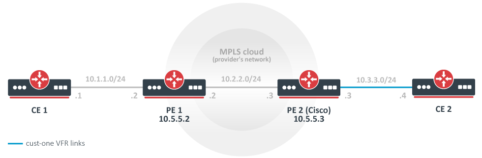
In this example, a rudimentary MPLS backbone (consisting of two Provider Edge (PE) routers PE1 and PE2) is created and configured to forward traffic between Customer Edge (CE) routers CE1 and CE2 routers that belong to cust-one VPN.
CE1 Router
/ip address add address=10.1.1.1/24 interface=ether1
# use static routing
/ip route add dst-address=10.3.3.0/24 gateway=10.1.1.2
CE2 Router
/ip address add address=10.3.3.4/24 interface=ether1
/ip route add dst-address=10.1.1.0/24 gateway=10.3.3.3
PE1 Router
/interface bridge add name=lobridge
/ip address add address=10.1.1.2/24 interface=ether1
/ip address add address=10.2.2.2/24 interface=ether2
/ip address add address=10.5.5.2/32 interface=lobridge
/ip vrf add name=cust-one interfaces=ether1
/mpls ldp add enabled=yes transport-address=10.5.5.2 lsr-id=10.5.5.2
/mpls ldp interface add interface=ether2
/routing bgp template set default as=65000

/routing bgp vpn
add vrf=cust-one \
  route-distinguisher=1.1.1.1:111 \
  import.route-targets=1.1.1.1:111 \
  import.router-id=cust-one \
  export.redistribute=connected \
  export.route-targets=1.1.1.1:111 \
  label-allocation-policy=per-vrf
/routing bgp connection
add template=default remote.address=10.5.5.3 address-families=vpnv4 local.address=10.5.5.2

# add route to the remote BGP peer's loopback address
/ip route add dst-address=10.5.5.3/32 gateway=10.2.2.3
PE2 Router (Cisco)
ip vrf cust-one
rd 1.1.1.1:111
route-target export 1.1.1.1:111
route-target import 1.1.1.1:111
exit

interface Loopback0
ip address 10.5.5.3 255.255.255.255

mpls ldp router-id Loopback0 force
mpls label protocol ldp

interface FastEthernet0/0
ip address 10.2.2.3 255.255.255.0
mpls ip

interface FastEthernet1/0
ip vrf forwarding cust-one
ip address 10.3.3.3 255.255.255.0

router bgp 65000
neighbor 10.5.5.2 remote-as 65000
neighbor 10.5.5.2 update-source Loopback0
address-family vpnv4
neighbor 10.5.5.2 activate
neighbor 10.5.5.2 send-community both
exit-address-family
address-family ipv4 vrf cust-one
redistribute connected
exit-address-family

ip route 10.5.5.2 255.255.255.255 10.2.2.2
Results
Check that VPNv4 route redistribution is working:
[admin@PE1] /routing/route> print detail where afi="vpn4"
Flags: X - disabled, F - filtered, U - unreachable, A - active;
c - connect, s - static, r - rip, b - bgp, o - ospf, d - dhcp, v - vpn, m - modem, a - ldp-address, l - l
dp-mapping, g - slaac, y - bgp-mpls-vpn;
H - hw-offloaded; + - ecmp, B - blackhole
 Ab   afi=vpn4 contribution=active dst-address=111.16.0.0/24&1.1.1.1:111 routing-table=main label=16
       gateway=111.111.111.4 immediate-gw=111.13.0.2%ether9 distance=200 scope=40 target-scope=30
       belongs-to="bgp-VPN4-111.111.111.4"
       bgp.peer-cache-id=*2C00011 .as-path="65511" .ext-communities=rt:1.1.1.1:111 .local-pref=100
       .atomic-aggregate=yes .origin=igp
       debug.fwp-ptr=0x202427E0

[admin@PE1] /routing/bgp/advertisements> print
 0 peer=to-pe2-1 dst=10.1.1.0/24 local-pref=100 origin=2 ext-communities=rt:1.1.1.1:111 atomic-aggregate=yes
Check that the 10.3.3.0 is installed in IP routes, in the cust-one route table:
[admin@PE1] > /ip route print where routing-table="cust-one"
Flags: D - DYNAMIC; A - ACTIVE; c, b, y - BGP-MPLS-VPN
Columns: DST-ADDRESS, GATEWAY, DISTANCE
# DST-ADDRESS     GATEWAY         DISTANCE
0 ADC 10.1.1.0/24 ether1@cust-one        0
1 ADb 10.3.3.0/24 10.5.5.3              20
Let's take a closer look at IP routes in cust-one VRF. The 10.1.1.0/24 IP prefix is a connected route that belongs to an interface that was configured to belong to cust-one VRF. The 10.3.3.0/24 IP prefix was advertised via BGP as a VPNv4 route from PE2 and is imported in this VRF routing table, because our configured import-route-targets matched the BGP extended communities attribute it was advertised with.
[admin@PE1] /routing/route> print detail where routing-table="cust-one"
Flags: X - disabled, F - filtered, U - unreachable, A - active;
c - connect, s - static, r - rip, b - bgp, o - ospf, d - dhcp, v - vpn, m - modem, a - ldp-address, l - l
dp-mapping, g - slaac, y - bgp-mpls-vpn;
H - hw-offloaded; + - ecmp, B - blackhole
 Ac   afi=ip4 contribution=active dst-address=10.1.1.0/24 routing-table=cust-one
       gateway=ether1@cust-one immediate-gw=ether1 distance=0 scope=10 belongs-to="connected"
       local-address=10.1.1.2%ether1@cust-one
       debug.fwp-ptr=0x202420C0

 Ay   afi=ip4 contribution=active dst-address=10.3.3.0/24 routing-table=cust-one label=16
       gateway=10.5.5.3 immediate-gw=10.2.2.3%ether2 distance=20 scope=40 target-scope=30
       belongs-to="bgp-mpls-vpn-1-bgp-VPN4-10.5.5.3-import"
       bgp.peer-cache-id=*2C00011 .ext-communities=rt:1.1.1.1:111 .local-pref=100
       .atomic-aggregate=yes .origin=igp
       debug.fwp-ptr=0x20242840


[admin@PE1] /routing/route> print detail where afi="vpn4"
Flags: X - disabled, F - filtered, U - unreachable, A - active;
c - connect, s - static, r - rip, b - bgp, o - ospf, d - dhcp, v - vpn, m - modem, a - ldp-address, l - l
dp-mapping, g - slaac, y - bgp-mpls-vpn;
H - hw-offloaded; + - ecmp, B - blackhole
 Ay   afi=vpn4 contribution=active dst-address=10.1.1.0/24&1.1.1.1:111 routing-table=main label=19
       gateway=ether1@cust-one immediate-gw=ether1 distance=200 scope=40 target-scope=10
       belongs-to="bgp-mpls-vpn-1-connected-export"
       bgp.ext-communities=rt:1.1.1.1:1111 .atomic-aggregate=no .origin=incomplete
       debug.fwp-ptr=0x202426C0

 Ab   afi=vpn4 contribution=active dst-address=10.3.3.0/24&1.1.1.1:111 routing-table=main label=16
       gateway=10.5.5.3 immediate-gw=10.2.2.3%ether2 distance=200 scope=40 target-scope=30
       belongs-to="bgp-VPN4-10.5.5.3"
       bgp.peer-cache-id=*2C00011 .ext-communities=rt:1.1.1.1:111 .local-pref=100
       .atomic-aggregate=yes .origin=igp
       debug.fwp-ptr=0x202427E0
The same for Cisco:
PE2#show ip bgp vpnv4 all
BGP table version is 5, local router ID is 10.5.5.3
Status codes: s suppressed, d damped, h history, * valid, > best, i - internal,
r RIB-failure, S Stale
Origin codes: i - IGP, e - EGP, ? - incomplete
Network Next Hop Metric LocPrf Weight Path
Route Distinguisher: 1.1.1.1:111 (default for vrf cust-one)
*>i10.1.1.0/24 10.5.5.2 100 0 ?
*> 10.3.3.0/24 0.0.0.0 0 32768 ?

PE2#show ip route vrf cust-one
Routing Table: cust-one
Codes: C - connected, S - static, R - RIP, M - mobile, B - BGP
D - EIGRP, EX - EIGRP external, O - OSPF, IA - OSPF inter area
N1 - OSPF NSSA external type 1, N2 - OSPF NSSA external type 2
E1 - OSPF external type 1, E2 - OSPF external type 2
i - IS-IS, su - IS-IS summary, L1 - IS-IS level-1, L2 - IS-IS level-2
ia - IS-IS inter area, * - candidate default, U - per-user static route
o - ODR, P - periodic downloaded static route

Gateway of last resort is not set
10.0.0.0/24 is subnetted, 1 subnets
B 10.1.1.0 [200/0] via 10.5.5.2, 00:05:33
10.0.0.0/24 is subnetted, 1 subnets
C 10.3.3.0 is directly connected, FastEthernet1/0
You should be able to ping from CE1 to CE2 and vice versa.
[admin@CE1] > /ping 10.3.3.4
10.3.3.4 64 byte ping: ttl=62 time=18 ms
10.3.3.4 64 byte ping: ttl=62 time=13 ms
10.3.3.4 64 byte ping: ttl=62 time=13 ms
10.3.3.4 64 byte ping: ttl=62 time=14 ms
4 packets transmitted, 4 packets received, 0% packet loss
round-trip min/avg/max = 13/14.5/18 ms
A more complicated setup (changes only)
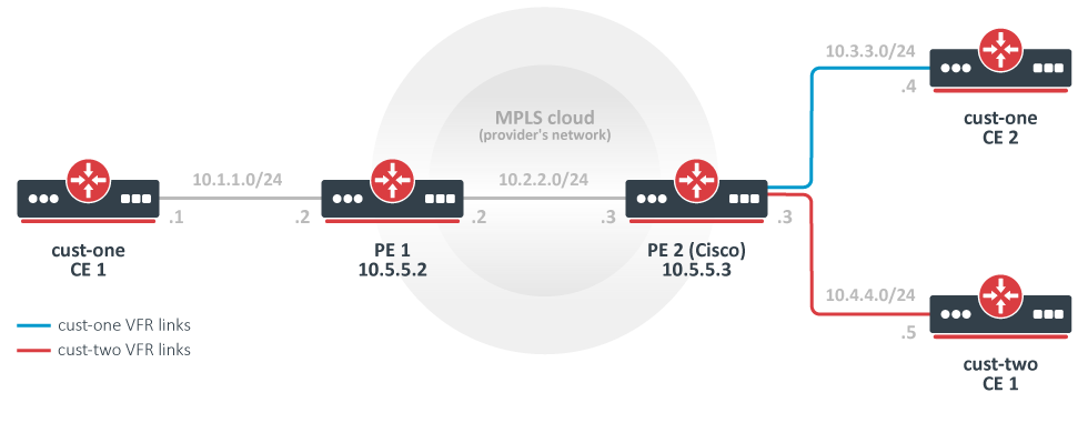
As opposed to the simplest setup, in this example, we have two customers: cust-one and cust-two.
We configure two VPNs for them, cust-one and cust-two respectively, and exchange all routes between them. (This is also called "route leaking").
Note that this could be not the most typical setup, because routes are usually not exchanged between different customers. In contrast, by default, it should not be possible to gain access from one VRF site to a different VRF site in another VPN. (This is the "Private" aspect of VPNs.) Separate routing is a way to provide privacy, and it is also required to solve the problem of overlapping IP network prefixes. Route exchange is in direct conflict with these two requirements but may sometimes be needed (e.g. temp. solution when two customers are migrating to a single network infrastructure).
CE1 Router, cust-one
/ip route add dst-address=10.4.4.0/24 gateway=10.1.1.2
CE2 Router, cust-one
/ip route add dst-address=10.4.4.0/24 gateway=10.3.3.3
CE1 Router,cust-two
/ip address add address=10.4.4.5 interface=ether1
/ip route add dst-address=10.1.1.0/24 gateway=10.3.3.3
/ip route add dst-address=10.3.3.0/24 gateway=10.3.3.3
PE1 Router
# replace the old BGP VPN with this:
/routing bgp vpn
add vrf=cust-one \
  export.redistribute=connected \
  route-distinguisher=1.1.1.1:111 \
  import.route-targets=1.1.1.1:111,2.2.2.2:222  \
  export.route-targets=1.1.1.1:111
PE2 Router (Cisco)
ip vrf cust-one
rd 1.1.1.1:111
route-target export 1.1.1.1:111
route-target import 1.1.1.1:111
route-target import 2.2.2.2:222
exit

ip vrf cust-two
rd 2.2.2.2:222
route-target export 2.2.2.2:222
route-target import 1.1.1.1:111
route-target import 2.2.2.2:222
exit

interface FastEthernet2/0
ip vrf forwarding cust-two
ip address 10.4.4.3 255.255.255.0

router bgp 65000
address-family ipv4 vrf cust-two
redistribute connected
exit-address-family
Variation: replace the Cisco with another MT
PE2 Mikrotik config
/interface bridge add name=lobridge
/ip address
add address=10.2.2.3/24 interface=ether1
add address=10.3.3.3/24 interface=ether2
add address=10.4.4.3/24 interface=ether3
add address=10.5.5.3/32 interface=lobridge
/ip vrf
add name=cust-one interfaces=ether2
add name=cust-two interfaces=ether3
/mpls ldp add enabled=yes transport-address=10.5.5.3
/mpls ldp interface add interface=ether1

/routing bgp template set default as=65000
/routing bgp vpn
add vrf=cust-one \
  export.redistribute=connected \
  route-distinguisher=1.1.1.1:111 \
  import.route-targets=1.1.1.1:111,2.2.2.2:222 \
  export.route-targets=1.1.1.1:111 \
add vrf=cust-two \
  export.redistribute=connected \
  route-distinguisher=2.2.2.2:222 \
  import.route-targets=1.1.1.1:111,2.2.2.2:222 \
  export.route-targets=2.2.2.2:222 \

/routing bgp connection
add template=default remote.address=10.5.5.2 address-families=vpnv4 local.address=10.5.5.3

# add route to the remote BGP peer's loopback address
/ip route add dst-address=10.5.5.2/32 gateway=10.2.2.2
Results
The output of /ip route print now is interesting enough to deserve detailed observation.
[admin@PE2] /ip route> print
Flags: X - disabled, A - active, D - dynamic,
C - connect, S - static, r - rip, b - bgp, o - ospf, m - mme,
B - blackhole, U - unreachable, P - prohibit
# DST-ADDRESS PREF-SRC GATEWAY DISTANCE
0 ADb 10.1.1.0/24 10.5.5.2 recurs... 20
1 ADC 10.3.3.0/24 10.3.3.3 ether2 0
2 ADb 10.4.4.0/24 20
3 ADb 10.1.1.0/24 10.5.5.2 recurs... 20
4 ADb 10.3.3.0/24 20
5 ADC 10.4.4.0/24 10.4.4.3 ether3 0
6 ADC 10.2.2.0/24 10.2.2.3 ether1 0
7 A S 10.5.5.2/32 10.2.2.2 reacha... 1
8 ADC 10.5.5.3/32 10.5.5.3 lobridge 0
The route 10.1.1.0/24 was received from a remote BGP peer and is installed in both VRF routing tables.
The routes 10.3.3.0/24 and 10.4.4.0/24 are also installed in both VRF routing tables. Each is a connected route in one table and a BGP route in another table. This has nothing to do with their being advertised via BGP. They are simply being "advertised" to the local VPNv4 route table and locally reimported after that. Import and export route-targets determine in which tables they will end up.
This can be deduced from its attributes - they don't have the usual BGP properties. (Route 10.4.4.0/24.)
[admin@PE2] /routing/route> print detail where routing-table=cust-one
...
References
RFC 4364: BGP/MPLS IP Virtual Private Networks (VPNs)
MPLS Fundamentals, chapter 7, Luc De Ghein, Cisco Press 2006
MikroTik newsletter
To follow the latest product and software news, make sure to read our newsletters in the blog section.