Overview
OSPF is Interior Gateway Protocol (IGP) designed to distribute routing information between routers belonging to the same Autonomous System (AS).
The protocol is based on link-state technology that has several advantages over distance-vector protocols such as RIP:
- no hop count limitations;
- multicast addressing is used to send routing information updates;
- updates are sent only when network topology changes occur;
- the logical definition of networks where routers are divided into areas
- transfers and tags external routes injected into AS.
However, there are a few disadvantages:
- OSPF is quite CPU and memory intensive due to the SPF algorithm and maintenance of multiple copies of routing information;
- more complex protocol to implement compared to RIP;
RouterOS implements the following standards:
- RFC 2328 - OSPF Version 2
- RFC 3101 - The OSPF Not-So-Stubby Area (NSSA) Option
- RFC 3630 - Traffic Engineering (TE) Extensions to OSPF Version 2
- RFC 4577 - OSPF as the Provider/Customer Edge Protocol for BGP/MPLS IP Virtual Private Networks (VPNs)
- RFC 5329 - Traffic Engineering Extensions to OSPF Version 3
- RFC 5340 - OSPF for IPv6
- RFC 5643 - Management Information Base for OSPFv3
- RFC 6549 - OSPFv2 Multi-Instance Extensions
- RFC 6565 - OSPFv3 as a Provider Edge to Customer Edge (PE-CE) Routing Protocol
- RFC 6845 - OSPF Hybrid Broadcast and Point-to-Multipoint Interface Type
- RFC 7471 - OSPF Traffic Engineering (TE) Metric Extensions
OSPF Terminology
Before we move on let's familiarise ourselves with terms important for understanding the operation of the OSPF. These terms will be used throughout the article.
- Neighbor - connected (adjacent) router that is running OSPF with the adjacent interface assigned to the same area. Neighbors are found by Hello packets (unless manually configured).
- Adjacency - logical connection between a router and its corresponding DR and BDR. No routing information is exchanged unless adjacencies are formed.
- Link - link refers to a network or router interface assigned to any given network.
- Interface - physical interface on the router. The interface is considered a link when it is added to OSPF. Used to build link database.
- LSA - Link State Advertisement, data packet contains link-state and routing information, that is shared among OSPF Neighbors.
- DR - Designated Router, chosen router to minimize the number of adjacencies formed. The option is used in broadcast networks.
- BDR -Backup Designated Router, hot standby for the DR. BDR receives all routing updates from adjacent routers, but it does not flood LSA updates.
- Area - areas are used to establish a hierarchical network.
- ABR - Area Border Router, router connected to multiple areas. ABRs are responsible for summarization and update suppression between connected areas.
- ASBR - Autonomous System Boundary Router, router connected to an external network (in a different AS). If you import other protocol routes into OSPF from the router it is now considered ASBR.
- NBMA - Non-broadcast multi-access, networks allow multi-access but have no broadcast capability. Additional OSPF neighbor configuration is required for those networks.
- Broadcast - Network that allows broadcasting, for example, Ethernet.
- Point-to-point - Network type eliminates the need for DRs and BDRs
- Router-ID - IP address used to identify the OSPF router. If the OSPF Router-ID is not configured manually, a router uses one of the IP addresses assigned to the router as its Router-ID.
- Link State - The term link-state refers to the status of a link between two routers. It defines the relationship between a router's interface and its neighboring routers.
- Cost - Link-state protocols assign a value to each link called cost. the cost value depends on the speed of the media. A cost is associated with the outside of each router interface. This is referred to as interface output cost.
- Autonomous System - An autonomous system is a group of routers that use a common routing protocol to exchange routing information.
Basic Configuration Example
To start OSPF v2 and v3 instances, the first thing to do is to add the instance and the backbone area:
/routing ospf instance
add name=v2inst version=2 router-id=1.2.3.4
add name=v3inst version=3 router-id=1.2.3.4
/routing ospf area
add name=backbone_v2 area-id=0.0.0.0 instance=v2inst
add name=backbone_v3 area-id=0.0.0.0 instance=v3inst
At this point, we can add a template. The template is used to match interfaces on which OSPF should be running, it can be done either by specifying the network or interface directly.
/routing ospf interface-template
add networks=192.168.0.0/24 area=backbone_v2
add networks=2001:db8::/64 area=backbone_v3
add interfaces=ether1 area=backbone_v3
Routing Table Calculation
Link state database describes the routers and links that interconnect them and are appropriate for forwarding. It also contains the cost (metric) of each link. This metric is used to calculate the shortest path to the destination network.
Each router can advertise a different cost for the router's own link direction, making it possible to have asymmetric links (packets to the destination travel over one path, but the response travels a different path). Asymmetric paths are not very popular, because it makes it harder to find routing problems.
The value of the cost can be changed in the OSPF interface template configuration menu, for example, to add an ether2 interface with a cost of 100:
/routing ospf interface-template
add interfaces=ether2 cost=100 area=backbone_v2
The cost of an interface on Cisco routers is inversely proportional to the bandwidth of that interface. A higher bandwidth indicates a lower cost. If similar costs are necessary on RouterOS, then use the following formula:
Cost = 100000000/bw in bps.
OSPF router is using Dijkstra's Shortest Path First (SPF) algorithm to calculate the shortest path. The algorithm places the router at the root of a tree and calculates the shortest path to each destination based on the cumulative cost required to reach the destination. Each router calculates its own tree even though all routers are using the same link-state database.
SPT Calculation
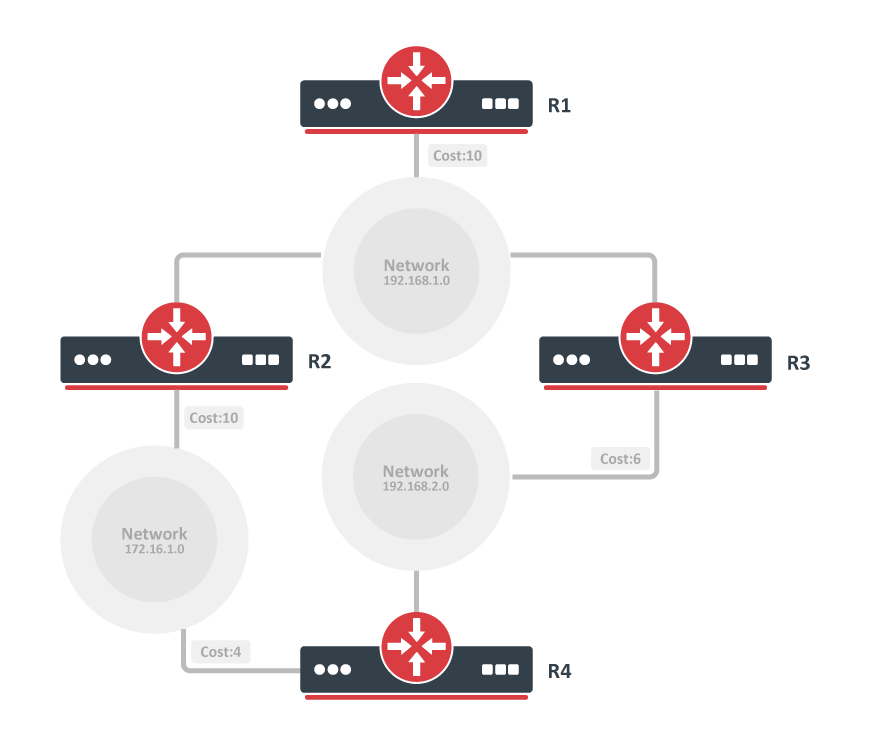
Assume we have the following network. The network consists of 4(four) routers. OSPF costs for outgoing interfaces are shown near the line that represents the link. In order to build the shortest-path tree for router R1, we need to make R1 the root and calculate the smallest cost for each destination.
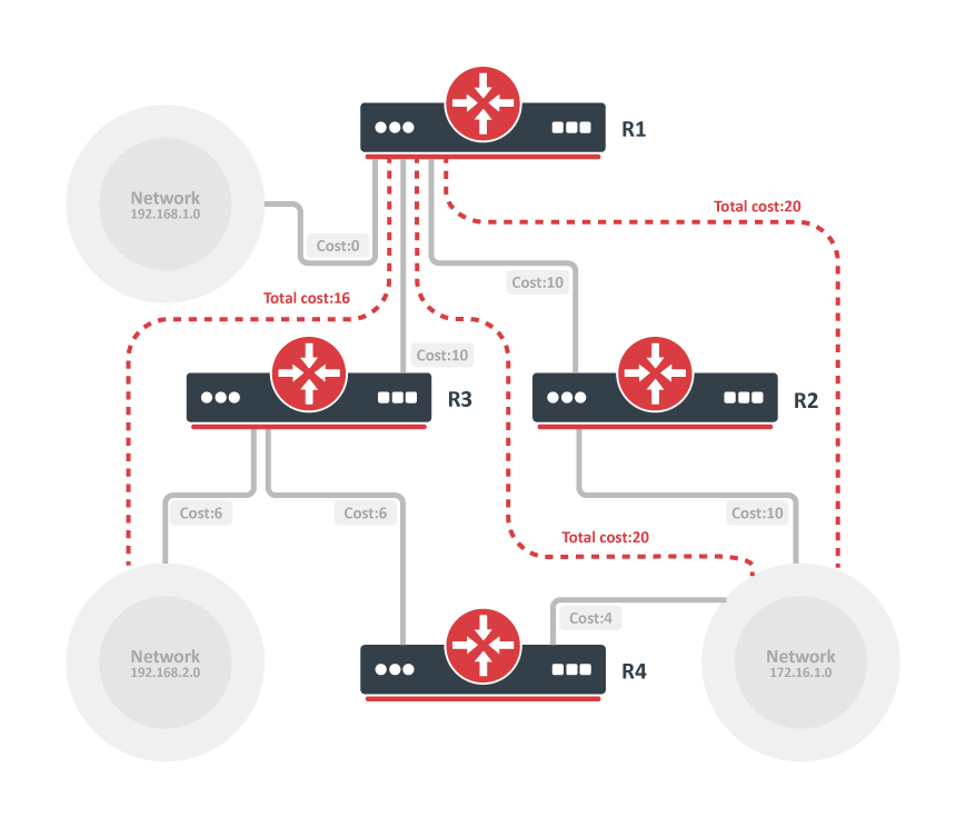
As you can see from the image above multiple shortest paths have been found to the 172.16.1.0 network, allowing load balancing of the traffic to that destination called equal-cost multipath (ECMP). After the shortest-path tree is built, a router starts to build the routing table accordingly. Networks are reached consequently to the cost calculated in the tree.
Routing table calculation looks quite simple, however, when some of the OSPF extensions are used or OSPF areas are calculated, routing calculation gets more complicated.
Forwarding Address
OSPF router can set the forwarding-address to something other than itself which indicates that an alternate next-hop is possible. Mostly forwarding address is set to 0.0.0.0 suggesting that the route is reachable only via the advertising router.
The forwarding address is set in LSA if the following conditions are met:
- OSPF must be enabled on the next-hop interface
- Next-hop address falls into the network provided by OSPF networks
A router that receives such LSA can use a forwarding address if OSPF is able to resolve the forwarding address. If forwarding address is not resolved directly - router sets nexthop for forwading address from LSA as a gateway, if forwarding address is not resolved at all - the gateway will be originator-id. Resolve happens only using OSPF instance routes, not the whole routing table.
Let's look at the example setup below:
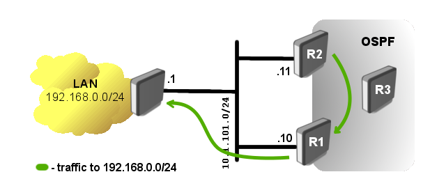
Router R1 has a static route to the external network 192.168.0.0/24. OSPF is running between R1, R2, and R3, and the static route is distributed across the OSPF network.
The problem in such a setup is obvious, R2 can not reach the external network directly. Traffic going to the LAN network from R2 will be forwarded over the router R1, but if we look at the network diagram we can see that more R2 can directly reach the router where the LAN network i located.
So knowing the forwarding address conditions, we can make router R1 to set the forwarding address. We simply need to add 10.1.101.0/24 network to OSPF networks in the router's R1 configuration:
/routing/ospf/interface-template add area=backbone_v2 networks=10.1.101.0/24
Now lets verify that forwarding address is actually working:
[admin@r2] /ip/route> print where dst-address=192.168.0.0/24
Flags: D - DYNAMIC; A - ACTIVE; o, y - COPY
Columns: DST-ADDRESS, GATEWAY, DISTANCE
    DST-ADDRESS       GATEWAY            DISTANCE
DAo 192.168.0.0/24    10.1.101.1%ether1       110
On all OSPF routers you will see LSA set with forwarding address other than 0.0.0.0
[admin@r2] /routing/ospf/lsa> print where id=192.168.0.0
Flags: S - self-originated, F - flushing, W - wraparound; D - dynamic

 1  D instance=default_ip4 type="external" originator=10.1.101.10 id=192.168.0.0
      sequence=0x80000001 age=19 checksum=0xF336 body=
        options=E
        netmask=255.255.255.0
        forwarding-address=10.1.101.1
        metric=10 type-1
        route-tag=0
OSPF adjacency between routers in the 10.1.101.0/24 network is not required
Neighbour Relationship and Adjacency
OSPF is a link-state protocol that assumes that the interface of the router is considered an OSPF link. Whenever OSPF is started, it adds the state of all the links in the local link-state database.
There are several steps before the OSPF network becomes fully functional:
- Neighbors discovery
- Database Synchronization
- Routing calculation
Link-state routing protocols are distributing and replicating database that describes the routing topology. The link-state protocol's flooding algorithm ensures that each router has an identical link-state database and the routing table is calculated based on this database.
After all the steps above are completed link-state database on each neighbor contains full routing domain topology (how many other routers are in the network, how many interfaces routers have, what networks link between router connects, cost of each link, and so on).
Communication Between OSPF Routers
OSPF operates over the IP network layer using protocol number 89.
A destination IP address is set to the neighbor's IP address or to one of the OSPF multicast addresses AllSPFRouters (224.0.0.5) or AllDRRouters (224.0.0.6). The use of these addresses is described later in this article.
Every OSPF packet begins with a standard 24-byte header.
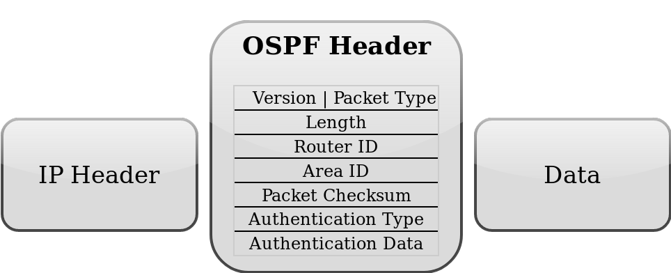
| Field | Description |
|---|---|
| Packet type | There are several types of OSPF packets: Hello packet, Database Description (DD) packet, Link state request packet, Link State Update packet, and Link State Acknowledgement packet. All of these packets except the Hello packet are used in link-state database synchronization. |
| Router ID | one of the router's IP addresses unless configured manually |
| Area ID | Allows OSPF router to associate the packet to the proper OSPF area. |
| Checksum | Allows receiving router to determine if a packet was damaged in transit. |
| Authentication fields | These fields allow the receiving router to verify that the packet's contents were not modified and that packet really came from the OSPF router whose Router ID appears in the packet. |
There are five different OSPF packet types used to ensure proper LSA flooding over the OSPF network.
- Hello packet - used to discover OSPF neighbors and build adjacencies.
- Database Description (DD) - check for Database synchronization between routers. Exchanged after adjacencies are built.
- Link-State Request (LSR) - used to request up-to-date pieces of the neighbor's database. Out-of-date parts of the routing database are determined after the DD exchange.
- Link-State Update (LSU) - carries a collection of specifically requested link-state records.
- Link-State Acknowledgment (LSack) - is used to acknowledge other packet types that way introducing reliable communication.
Neighbors Discovery
OSPF discovers potential neighbors by periodically sending Hello packets out of configured interfaces. By default Hello packets are sent out at 10-second intervals which can be changed by setting hello-interval in OSPF interface settings. The router learns the existence of a neighboring router when it receives the neighbor's Hello in return with matching parameters.
The transmission and reception of Hello packets also allow a router to detect the failure of the neighbor. If Hello packets are not received within dead-interval (which by default is 40 seconds) router starts to route packets around the failure. "Hello" protocol ensures that the neighboring routers agree on the Hello interval and Dead interval parameters, preventing situations when not in time received Hello packets mistakenly bring the link down.
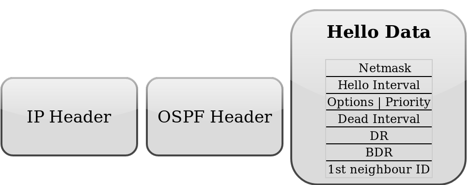
| Field | Description |
|---|---|
| network mask | The IP mask of the originating router's interface IP address. |
| hello interval | the period between Hello packets (default 10s) |
| options | OSPF options for neighbor information |
| router priority | an 8-bit value used to aid in the election of the DR and BDR. (Not set in p2p links) |
| router dead interval | time interval has to be received before considering the neighbor is down. ( By default four times bigger than the Hello interval) |
| DR | the router-id of the current DR |
| BDR | the router-id of the current BDR |
| Neighbor router IDs | a list of router ids for all the originating router's neighbors |
On each type of network segment Hello protocol works a little differently. It is clear that on point-to-point segments only one neighbor is possible and no additional actions are required. However, if more than one neighbor can be on the segment additional actions are taken to make OSPF functionality even more efficient.
Two routers do not become neighbors unless the following conditions are met.
- Two-way communication between routers is possible. Determined by flooding Hello packets.
- The interface should belong to the same area;
- The interface should belong to the same subnet and have the same network mask unless it has network-type configured as point-to-point;
- Routers should have the same authentication options, and have to exchange the same password (if any);
- Hello and Dead intervals should be the same in Hello packets;
- External routing and NSSA flags should be the same in Hello packets.
Network mask, Priority, DR, and BDR fields are used only when the neighbors are connected by a broadcast or NBMA network segment.
Discovery on Broadcast Subnets
The attached node to the broadcast subnet can send a single packet and that packet is received by all other attached nodes. This is very useful for auto-configuration and information replication. Another useful capability in broadcast subnets is multicast. This capability allows sending a single packet which will be received by nodes configured to receive multicast packets. OSPF is using this capability to find OSPF neighbors and detect bidirectional connectivity.
Each OSPF router joins the IP multicast group AllSPFRouters (224.0.0.5), then the router periodically multicasts its Hello packets to the IP address 224.0.0.5. All other routers that joined the same group will receive a multicasted Hello packet. In that way, OSPF routers maintain relationships with all other OSPF routers by sending a single packet instead of sending a separate packet to each neighbor on the segment.
This approach has several advantages:
Automatic neighbor discovery by multicasting or broadcasting Hello packets. Less bandwidth usage compared to other subnet types. On the broadcast segment, there are n*(n-1)/2 neighbor relations, but those relations are maintained by sending only n Hellos. If the broadcast has the multicast capability, then OSPF operates without disturbing non-OSPF nodes on the broadcast segment. If the multicast capability is not supported all routers will receive broadcasted Hello packets even if the node is not an OSPF router.
Discovery on NBMA Subnets
Non-broadcast multiaccess (NBMA) segments are similar to broadcast. Support more than two routers, the only difference is that NBMA does not support a data-link broadcast capability. Due to this limitation, OSPF neighbors must be discovered initially through configuration. On RouterOS static neighbor configuration is set in the /routing ospf static-neighbor menu. To reduce the amount of Hello traffic, most routers attached to the NBMA subnet should be assigned a Router Priority of 0 (set by default in RouterOS). Routers that are eligible to become Designated Routers should have priority values other than 0. It ensures that during the election of DR and BDR Hellos are sent only to eligible routers.
Discovery on PTMP Subnets
Point-to-MultiPoint treats the network as a collection of point-to-point links.
By design, PTMP networks should not have broadcast capabilities, which means that OSPF neighbors (the same way as for NBMA networks) must be discovered initially through configuration and all communication happens by sending unicast packets directly between neighbors. On RouterOS static neighbor configuration is set in the /routing ospf static-neighbor menu. Designated Routers and Backup Designated Routers are not elected on Point-to-multipoint subnets.
For PTMP networks that do support broadcast, a hybrid type named "ptmp-broadcast" can be used. This network type uses multicast Hellos to discover neighbors automatically and detect bidirectional communication between neighbors. After neighbor detection "ptmp-broacast" sends unicast packets directly to the discovered neighbors. This mode is compatible with the RouterOS v6 "ptmp" type.
Master-Slave Relation
Before database synchronization can begin, a hierarchy order of exchanging information must be established, which determines which router sends Database Descriptor (DD) packets first (Master). The master router is elected based on the highest priority and if priority is not set then the router ID will be used. Note that it is a router priority-based relation to arranging the exchanging data between neighbors which does not affect DR/BDR election (meaning that DR does not always have to be Master).
Database Synchronization
Link-state Database synchronization between OSPF routers is very important. Unsynchronized databases may lead to incorrectly calculated routing tables which could cause routing loops or black holes.
There are two types of database synchronizations:
- initial database synchronization
- reliable flooding.
When the connection between two neighbors first comes up, initial database synchronization will happen. OSPF is using explicit database download when neighbor connections first come up. This procedure is called Database exchange. Instead of sending the entire database, the OSPF router sends only its LSA headers in a sequence of OSPF Database Description (DD) packets. The router will send the next DD packet only when the previous packet is acknowledged. When an entire sequence of DD packets has been received, the router knows which LSAs it does not have and which LSAs are more recent. The router then sends Link-State Request (LSR) packets requesting desired LSAs, and the neighbor responds by flooding LSAs in Link-State Update (LSU) packets. After all the updates are received neighbors are said to be fully adjacent.
Reliable flooding is another database synchronization method. It is used when adjacencies are already established and the OSPF router wants to inform other routers about LSA changes. When the OSPF router receives such Link State Update, it installs a new LSA in the link-state database, sends an acknowledgment packet back to the sender, repackages LSA in new LSU, and sends it out to all interfaces except the one that received the LSA in the first place.
OSPF determines if LSAs are up to date by comparing sequence numbers. Sequence numbers start with 0×80000001, the larger the number, the more recent the LSA is. A sequence number is incremented each time the record is flooded and the neighbor receiving the update resets the Maximum age timer. LSAs are refreshed every 30 minutes, but without a refresh, LSA remains in the database for the maximum age of 60 minutes.
Databases are not always synchronized between all OSPF neighbors, OSPF decides whether databases need to be synchronized depending on the network segment, for example, on point-to-point links databases are always synchronized between routers, but on Ethernet networks databases are synchronized between certain neighbor pairs.
Synchronization on Broadcast Subnets
On the broadcast segment, there are n*(n-1)/2 neighbor relations, it will be a huge amount of Link State Updates and Acknowledgements sent over the subnet if the OSPF router will try to synchronize with each OSPF router on the subnet.
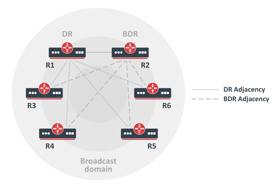
This problem is solved by electing one Designated Router and one Backup Designated Router for each broadcast subnet. All other routers are synchronizing and forming adjacencies only with those two elected routers. This approach reduces the number of adjacencies from n*(n-1)/2 to only 2n-3.
The image on the right illustrates adjacency formations on broadcast subnets. Routers R1 and R2 are Designated Routers and Backup Designated routers respectively. For example, if R3 wants to flood Link State Update (LSU) to both R1 and R2, a router sends LSU to the IP multicast address AllDRouters (224.0.0.6) and only DR and BDR listen to this multicast address. Then Designated Router sends LSU addressed to AllSPFRouters, updating the rest of the routers.
DR Election
DR and BDR routers are elected from data received in the Hello packet. The first OSPF router on a subnet is always elected as Designated Router, when a second router is added it becomes Backup Designated Router. When an existing DR or BDR fails new DR or BDR is elected to take into account configured router priority. The router with the highest priority becomes the new DR or BDR.
Being Designated Router or Backup Designated Router consumes additional resources. If Router Priority is set to 0, then the router is not participating in the election process. This is very useful if certain slower routers are not capable of being DR or BDR.
Synchronization on NBMA Subnets
Database synchronization on NBMA networks is similar to that on broadcast networks. DR and BDR are elected, databases initially are exchanged only with DR and BDR routers and flooding always goes through the DR. The only difference is that Link State Updates must be replicated and sent to each adjacent router separately.
Synchronization on PTMP Subnets
On PTMP subnets OSPF router becomes adjacent to all other routes with which it can communicate directly.
Understanding OSPF Areas
A distinctive feature of OSPF is the possibility to divide AS into multiple routing Areas which contain their own set of neighbors.
Imagine a large network with 300+ routers and multiple links between them. Whenever link flaps or some other topology change happens in the network, this change will be flooded to all OSPF devices in the network resulting in a quite heavy load on the network and even downtime since network convergence may take some time for such a large network.
A large single-area network can produce serious issues:
- Each router recalculates the database every time whenever network topology change occurs, the process takes CPU resources.
- Each router holds an entire link-state database, which shows the topology of the entire network, it takes memory resources.
- A complete copy of the routing table and a number of routing table entries may be significantly greater than the number of networks, which can take even more memory resources.
- Updating large databases requires more bandwidth.
The introduction of areas allows for better resource management since topology change inside one area is not flooded to other areas in the network. The concept of areas enables simplicity in network administration as well as routing summarization between areas significantly reducing the database size that needs to be stored on each OSPF neighbor. This means that each area has its own link-state database and corresponding shortest-path tree.
The structure of an area is invisible to other areas. This isolation of knowledge makes the protocol more scalable if multiple areas are used; routing table calculation takes fewer CPU resources and routing traffic is reduced.
However, multi-area setups create additional complexity. It is not recommended to separate areas with fewer than 50 routers. The maximum number of routers in one area is mostly dependent on the CPU power you have for routing table calculation.
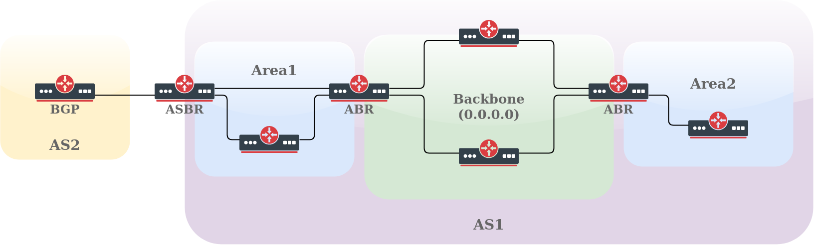
OSPF area has unique 32-bit identification (Area ID) and the area with an Area ID of 0.0.0.0 (called the Backbone area) is the main one where any other area should connect. Routers that connect to more than one area are called ABR (Area Border Routers), and their main responsibility is summarization and update suppression between connected areas. The router connecting to another routing domain is called ASBR (Autonomous System Boundary Router).
Each area has its own link-state database, consisting of router-LSAs and network-LSAs describing how all routers within that area are interconnected. Detailed knowledge of the area's topology is hidden from all other areas; router-LSAs and network-LSAs are not flooded beyond the area's borders. Area Border Routers (ABRs) leak addressing information from one area into another in OSPF summary-LSAs. This allows one to pick the best area border router when forwarding data to destinations from another area and is called intra-area routing.
Routing information exchange between areas is essentially a Distance Vector algorithm and to prevent algorithm convergence problems, such as counting to infinity, all areas are required to attach directly to the backbone area making a simple hub-and-spoke topology. The area-ID of the backbone area is always 0.0.0.0 and can not be changed.
RouterOS area configuration is done in the /routing/ospf/area menu. For example, a configuration of an ABR router with multiple attached areas, one Stub area, and one default area:
/routing ospf area
add name=backbone_v2 area-id=0.0.0.0 instance=v2inst
add name=stub_area area-id=1.1.1.1 instance=v2inst type=stub
add name=another_area area-id=2.2.2.2 instance=v2inst type=default
OSPF can have 5 types of areas. Each area type defines what type of LSAs the area supports:
- standard/default - OSPF packets can normally be transmitted in this area, it supports types 1,2,3,4 and 5 LSAs
- backbone - as already mentioned this is the main area where any other area connects. It is basically the same as the standard area but identified with ID 0.0.0.0
- stub - this area does not accept any external routes
- totally stubby - a variation of the stub area
- not-so-stubby (NSSA) - a variation of the stub area
LSA Types
Before we continue a detailed look at each area type, let's get familiar with LSA types:
- type 1 - (Router LSA) Sent by routers within the Area, including the list of directly attached links. Do not cross the ABR or ASBR.
- type 2 - (Network LSA) Generated for every "transit network" within an area. A transit network has at least two directly attached OSPF routers. Ethernet is an example of a Transit Network. A Type 2 LSA lists each of the attached routers that make up the transit network and is generated by the DR.
- type 3 - (Summary LSA) The ABR sends Type 3 Summary LSAs. A Type 3 LSA advertises any networks owned by an area to the rest of the areas in the OSPF AS. By default, OSPF advertises Type 3 LSAs for every subnet defined in the originating area, which can cause flooding problems, so it´s a good idea to use a manual summarization at the ABR.
- type 4 - (ASBR-Summary LSA) It announces the ASBR address, it shows “where” the ASBR is located, announcing its address instead of its routing table.
- type 5 - (External LSA) Announces the Routes learned through the ASBR, are flooded to all areas except Stub areas. This LSA divides into two sub-types: external type 1 and external type 2.
- type 6 - (Group Membership LSA) This was defined for Multicast extensions to OSPF and is not used by RouterOS.
- type 7 - type 7 LSAs are used to tell the ABRs about these external routes imported into the NSSA area. Area Border Router then translates these LSAs to type 5 external LSAs and floods as normal to the rest of the OSPF network
- type 8 - External Attributes LSA (OSPFv2) / link-local LSA (OSPFv3)
- type 9 - Link-Local Scope Opaque (OSPFv2) / Intra Area Prefix LSA (OSPFv3). LSA of this type is not flooded beyond the local (sub)network.
- type 10 - Area Local Scope Opaque. LSA of this type is not flooded beyond the scope of its associated area.
- type 11 - Opaque LSA which is flooded throughout the AS (scope is the same as type 5). It is not flooded in stub areas and NSSAs.
If we do not have any ASBR, there are no LSA Types 4 and 5 in the network.
Standard Area
This area supports 1, 2, 3, 4, and 5 LSAs.
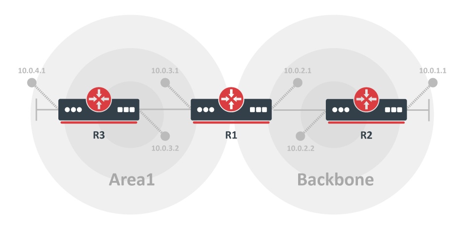
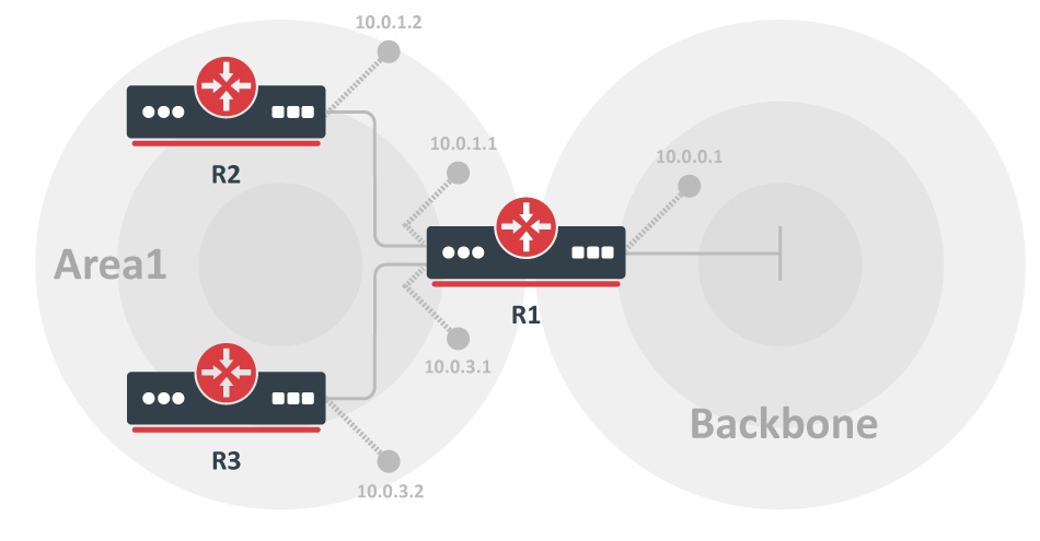
Simple multi-area network using default area. In this example, all networks from area1 are flooded to the backbone and all networks from the backbone are flooded to area1.
R1:
/ip address add address=10.0.3.1/24 interface=ether1
/ip address add address=10.0.2.1/24 interface=ether2
/routing ospf instance
add name=v2inst version=2 router-id=1.0.0.1
/routing ospf area
add name=backbone_v2 area-id=0.0.0.0 instance=v2inst
add name=area1 area-id=1.1.1.1 type=default instance=v2inst
/routing ospf interface-template
add networks=10.0.2.0/24 area=backbone_v2
add networks=10.0.3.0/24 area=area1
R2:
/ip address add address=10.0.1.1/24 interface=ether2
/ip address add address=10.0.2.2/24 interface=ether1
/routing ospf instance
add name=v2inst version=2 router-id=1.0.0.2
/routing ospf area
add name=backbone_v2 area-id=0.0.0.0
/routing ospf interface-template
add networks=10.0.2.0/24 area=backbone_v2
add networks=10.0.1.0/24 area=backbone_v2
R3:
/ip address add address=10.0.3.2/24 interface=ether2
/ip address add address=10.0.4.1/24 interface=ether1
/routing ospf instance
add name=v2inst version=2 router-id=1.0.0.3
/routing ospf area
add name=area1 area-id=1.1.1.1 type=stub instance=v2inst
/routing ospf interface-template
add networks=10.0.3.0/24 area=area1
add networks=10.0.4.0/24 area=area1
Stub Area
The main purpose of stub areas is to keep such areas from carrying external routes. Routing from these areas to the outside world is based on a default route. A stub area reduces the database size inside an area and reduces the memory requirements of routers in the area.
The stub area has a few restrictions, ASBR routers cannot be internal to the area, stub area cannot be used as a transit area for virtual links. The restrictions are made because the stub area is mainly configured not to carry external routes.
This area supports 1, 2, and 3 LSAs.
Let's consider the example above. Area1 is configured as a stub area meaning that routers R2 and R3 will not receive any routing information from the backbone area except the default route.
R1:
/routing ospf instance
add name=v2inst version=2 router-id=1.0.0.1
/routing ospf area
add name=backbone_v2 area-id=0.0.0.0 instance=v2inst
add name=area1 area-id=1.1.1.1 type=stub instance=v2inst

/routing ospf interface-template
add networks=10.0.0.0/24 area=backbone_v2
add networks=10.0.1.0/24 area=area1
add networks=10.0.3.0/24 area=area1
R2:
/routing ospf instance
add name=v2inst version=2 router-id=1.0.0.2
/routing ospf area
add name=area1 area-id=1.1.1.1 type=stub instance=v2inst
/routing ospf interface-template
add networks=10.0.1.0/24 area=area1
R3:
/routing ospf instance
add name=v2inst version=2 router-id=1.0.0.3
/routing ospf area
add name=area1 area-id=1.1.1.1 type=stub instance=v2inst
/routing ospf interface-template
add networks=10.0.3.0/24 area=area1
Totally Stubby Area
Totally stubby area is an extension of the stub area. A totally stubby area blocks external routes and summarized (inter-area) routes from going into the area. Only intra-area routes are injected into the area. Totally stubby area is configured as a stub area with an additional no-summaries flag. This area supports Type 1, Type 2 LSAs, and Type 3 LSAs with default routes.
/routing ospf area
add name=totally_stubby_area area-id=1.1.1.1 instance=v2inst type=stub no-summaries
NSSA
Not-so-stubby area (NSSA) is useful when it is required to inject external routes, but injection of type 5 LSA routes is not required.
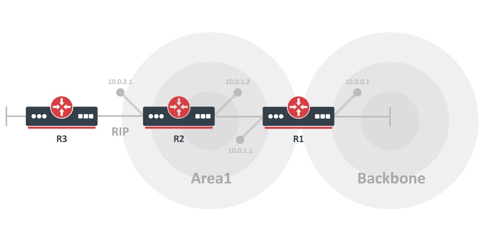
The illustration shows two areas (backbone and area1) and RIP connection to the router located in "area1". We need "area1" to be configured as a stub area, but it is also required to inject external RIP routes in the backbone. Area1 should be configured as NSSA in this case.
The configuration example does not cover RIP configuration.
R1:
/routing ospf instance
add name=v2inst version=2 router-id=1.0.0.1
/routing ospf area
add name=backbone_v2 area-id=0.0.0.0 instance=v2inst
add name=area1 area-id=1.1.1.1 type=nssa instance=v2inst
/routing ospf interface-template
add networks=10.0.0.0/24 area=backbone_v2
add networks=10.0.1.0/24 area=area1
R2:
/routing ospf instance
add name=v2inst version=2 router-id=1.0.0.2
/routing ospf area
add name=area1 area-id=1.1.1.1 type=nssa instance=v2inst
/routing ospf interface-template
add networks=10.0.1.0/24 area=area1
Virtual links cannot be used over NSSA areas.
External Routing Information and Default Route
On the edge of an OSPF routing domain, you can find routers called AS boundary routers (ASBRs) that run one of the other routing protocols. The job of those routers is to import routing information learned from other routing protocols into the OSPF routing domain. External routes can be imported at two separate levels depending on the metric type.
- type1 - OSPF metric is the sum of the internal OSPF cost and the external route cost
- type2 - OSPF metric is equal only to the external route cost.
Type 1 external paths are always preferred over type 2 external paths. When all paths are type 2 external paths, the paths with the smallest advertised type 2 metric are always preferred. (RFC2328)
External routes can be imported via the instance redistribute parameter. The example below will pick and redistribute all static and RIP routes:
/routing ospf instance
add name=v2inst version=2 router-id=1.2.3.4 redistribute=static,rip
Redistribution of default route is a special case where the originate-default the parameter should be used:
/routing ospf instance
set v2inst originate-default=if-installed
Since redistribution is controlled by "originate-default" and "redistribute" parameter, it introduces some corner-cases for default route filtering.
- if
redistributeis enabled, then pick all routes matching redistribute parameters - If
originate-default=never, a default route will be rejected - run selected routes (or all routes if redistribute parameter is not set) through
out-select-chain(if configured) - run selected routes through
out-filter-chain(if configured) - if
originate-defaultis set toalwaysorif-installed:- OSPF creates a fake default route without attributes;
- runs this route through
out-filter-chainwhere attributes can be applied, but action is ignored (always accept);
For a complete list of redistribution values, see the reference manual.
Route Summarisation
Route summarization is a consolidation of multiple routes into one single advertisement. It is normally done at the area boundaries (Area Border Routers).
It is better to summarise in the direction of the backbone. That way the backbone receives all the aggregated routes and injects them into other areas already summarized. There are two types of summarization: inter-area and external route summarization.
Inter-area route summarization works on area boundaries (ABRs), it does not apply to external routes injected into OSPF via redistribution. By default, ABR creates a summary LSA for each route in a specific area and advertises it in adjacent areas.
Using ranges allows for creating only one summary LSA for multiple routes and sending only a single advertisement into adjacent areas, or suppressing advertisements altogether.
If a range is configured with the 'advertise' parameter, a single summary LSA is advertised for each range if there are any routes under the range in the specific area. Otherwise (when 'advertise' parameter disabled) no summary LSAs are created and advertised outside area boundaries at all.
Inter-area route summarization can be configured from the OSPF area range menu.
Let's consider that we have two areas backbone and area1, area1 has several /24 routes from the 10.0.0.0/16 range and there is no need to flood the backbone area with each /24 subnet if it can be summarized. On the router connecting area1 with the backbone we can set up the area range:
/routing ospf area range
add prefix=10.0.0.0/16 area=area1 advertise=yes cost=10
For an active range (i.e. one that has at least one OSPF route from the specified area falling under it), a route with the type 'blackhole' is created and installed in the routing table.
External route summarization can be achieved using routing filters. Let's consider the same example as above except that area1 has redistributed /24 routes from other protocols. To send a single summarised LSA, a blackhole route must be added and an appropriate routing filter to accept only summarised route:
/ip route add dst-address=10.0.0.0/16 blackhole
/routing ospf instance
set v2inst out-filter-chain=ospf_out
/routing filter rule
add chain=ospf_out rule="if (dst == 10.0.0.0/16) {accept} else {reject}"
Virtual Link
As it was mentioned previously all OSPF areas have to be attached to the backbone area, but sometimes the physical connection is not possible. To overcome this, areas can be attached logically by using virtual links.
There are two common scenarios when virtual links can be used:
- to glue together the fragmented backbone area
- to connect remote are without direct connection to the backbone
Partitioned Backbone
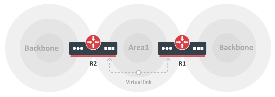
OSPF allows to linking of discontinuous parts of the backbone area using virtual links. This might be required when two separate OSPF networks are merged into one large network. Virtual links can be configured between separate ABRs that touch the backbone area from each side and have a common area.
The additional area could be created to become a transit area when a common area does not exist, it is illustrated in the image above.
Virtual Links are not required for non-backbone areas when they get partitioned. OSPF does not actively attempt to repair area partitions, each component simply becomes a separate area, when an area becomes partitioned. The backbone performs routing between the new areas. Some destinations are reachable via intra-area routing, the area partition requires inter-area routing.
However, to maintain full routing after the partition, an address range has not to be split across multiple components of the area partition.
No physical connection to a backbone
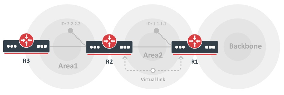
The area may not have a physical connection to the backbone, a virtual link is used to provide a logical path to the backbone of the disconnected area. A link has to be established between two ABRs that have a common area with one ABR connected to the backbone.
We can see that both R1 and R2 routers are ABRs and R1 is connected to the backbone area. Area2 will be used as a transit area and R1 is the entry point into the backbone area. A virtual link has to be configured on both routers.
Virtual link configuration is added in OSPF interface templates. If we take the example setup from the "no physical connection" illustration, then the virtual link configuration would look like this:
R1:
/routing ospf interface-template
add vlink-transit-area=area2 area=backbone_v2 type=virtual-link vlink-neighbor-id=2.2.2.2
R2:
/routing ospf interface-template
add vlink-transit-area=area2 area=backbone_v2 type=virtual-link vlink-neighbor-id=1.1.1.1