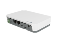
KNOT RB924i-2nD-BT5&BG77
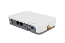
KNOT LR8 kit
...
RB924iR-2nD-BT5&BG77&R11e-LR8
KNOT LR9 kit
...
RB924iR-2nD-BT5&BG77&R11e-LR9
Safety Warnings
Before you work on any equipment, be aware of the hazards involved with electrical circuitry, and be familiar with standard practices for preventing accidents.
Ultimate disposal of this product should be handled according to all national laws and regulations.
The Installation of the equipment must comply with local and national electrical codes.
This unit is intended to be installed in the rackmount. Please read the mounting instructions carefully before beginning installation. Failure to use the correct hardware or to follow the correct procedures could result in a hazardous situation for people and damage to the system.
This product is intended to be installed indoors. Keep this product away from water, fire, humidity, or hot environments.
Use only the power supply and accessories approved by the manufacturer, and which can be found in the original packaging of this product.
Read the installation instructions before connecting the system to the power source.
We cannot guarantee that no accidents or damage will occur due to the improper use of the device. Please use this product with care and operate at your own risk!
In the case of device failure, please disconnect it from power. The fastest way to do so is by unplugging the power plug from the power outlet.
It is the customer's responsibility to follow local country regulations, including operation within legal frequency channels, output power, cabling requirements, and Dynamic Frequency Selection (DFS) requirements. All Mikrotik radio devices must be professionally installed.
...
| Info |
|---|
BG77 supports NB and GNSS. Both cannot be used together simultaneously. An example of the configuration to automate the switch between the cellular and GNSS priority is shown below under the Cellular and GNSS priority switch automation section. Please also check the guide at - WWAN and GNSS priority automatization. |
| Info |
|---|
External antennas must be connected to use the Narrow Band modem and GPS. Not provided with the package. |
Buttons and jumpers
Reset button
A port named "modem" is used for cellular connection (serial/PPP connection) and GNSS NMEA data:
| Code Block | ||
|---|---|---|
| ||
/port print
Flags: I - INACTIVE
Columns: DEVICE, NAME, CHANNELS, USED-BY, BAUD-RATE
#   DEVICE  NAME    CHANNELS  USED-BY  BAUD-RATE
0           modbus         1                9600
1 1-1.4 modem 5 115200 |
Default modem port channel assignment:
1 - GNSS NMEA output port;
2 - AT/modem port;
4 - AT/modem port - KNOT LORA kits and KNOT with an internal USB hub.
Cellular modem configuration
Unlike LTE devices, the KNOT BG77 by default does not provide a direct IP modem interface (LTE interface), but provides AT/modem serial port which is used for serial/PPP connection.
KNOT by default has a serial/PPP connection preset:
| Code Block | ||
|---|---|---|
| ||
/interface ppp-client print
Flags: X - disabled; R - running
 0 R  name="ppp-out1" max-mtu=1500 max-mru=1500 mrru=disabled port=modem data-channel=2 info-channel=4 apn="internet"
      pin="" user="" password="" profile=default phone="" dial-command="ATDT" modem-init="AT+QGPSCFG="priority",1"
      null-modem=no dial-on-demand=yes add-default-route=yes default-route-distance=1 use-peer-dns=yes keepalive-timeout=30
allow=pap,chap,mschap1,mschap2 |
For more details on modem port configuration please see the KNOT port configuration/map above.
For more details on serial/PPP connection please check the link.
GNSS configuration
You can find more information by checking the guide here.
BG77 modem shares the same receiver for IoT cellular connectivity and GNSS signal reception. The preferred service can be prioritized by using the modem-init string (configured under /interface ppp-client) and GNSS service init-string (configured under /system gps).
AT commands are:
AT+QGPSCFG="priority",0 → to prioritize GNSS;
AT+QGPSCFG="priority",1 → to prioritize cellular IoT connectivity;
AT+QGPSEND → to stop GNSS reception;
AT+QGPS=1 → to start GNSS reception.
Additionally, you can configure Supported GNSS Constellations with the help of the AT command:
AT+QGPSCFG="gnssconfig"[,<GNSS_config>]
,which takes effect only after the module is rebooted and where <GNSS_config> represents the Constellations themselves (can be "1" to "5"):
- 1 → GPS + GLONASS
- 2 → GPS + BeiDou
- 3 → GPS + Galileo
- 4 → GPS + QZSS
- 5 → Variable - one of the options (1–4) is selected based on MCC of the camped network
Cellular and GNSS priority switch automation
Automation can be achieved using ppp profile "on-down"script, "idle-timeout" features and PPP interface "dial on demand" setting.
When implemented, BG77 modem will use cellular data when there is internet traffic present (during this time GNSS coordinates are not received), and will automatically enable GPS reception when there is no internet traffic detected.
Idle-timeout parameter specifies the amount of time after which the link will be terminated if there is no activity present.
On-down script field allows you to configure a script that will be run every time the PPP interface goes down (including after idle-timeout inactivity). The script will set modem's priority to GNSS reception.
Dial-on-demand will make sure that PPP interface tries to establish the connection only when there is outgoing traffic present (additionally, the modem will automatically set WWAN/cellular connection priority). This will make sure that after idle-timeout occurs, the connection is not automatically reestablished unless outgoing packets are detected.
By combining the three features, you can achieve the scenario, where:
- If you have outgoing traffic, PPP interface is going to be up (because of the "dial on demand") and the priority will be set to the cellular connection. PPP interface's modem initialization AT command (that is configured under PPP interface's
modem-init="AT+QGPSCFG="priority",1"setting) for WWAN priority is sent. During this time, GPS coordinates will not be received. - If no traffic is detected after "idle-timeout" inactivity window, the PPP interface will go down and, because of the "dial on demand" setting, it will not establish the connection until outgoing packets are detected. This is where "on-down" script is run that switches WWAN priority to GNSS priority.
In order to implement it, simply add a new PPP profile:
| Code Block | ||
|---|---|---|
| ||
/ppp profile add idle-timeout=30s name=BG77 on-down="/interface ppp-client at-chat [find where modem-init=\"AT+QGPSCFG=\\\"priority\\\",1\"] input=\"AT+QGPSCFG=\\\"priority\\\",0\"" |
The example above, creates a new profile with the name "BG77", sets idle-timeout to 30 seconds, and enables the on-down script that will send GNSS priority AT command.
After that, make sure to apply this newly created profile onto the PPP interface:
| Code Block | ||
|---|---|---|
| ||
/interface ppp-client set [find] profile=BG77 |
And confirm that it was applied (profile=BG77):
| Code Block | ||
|---|---|---|
| ||
/interface ppp-client print
Flags: X - disabled; R - running
0 R name="ppp-out1" max-mtu=1500 max-mru=1500 mrru=disabled port=modem data-channel=2 info-channel=2
apn="internet" pin="" user="" password="" profile=BG77 phone="" dial-command="ATDT"
modem-init="AT+QGPSCFG="priority",1" null-modem=no dial-on-demand=yes add-default-route=yes
default-route-distance=1 use-peer-dns=yes keepalive-timeout=30 allow=pap,chap,mschap1,mschap2
|
Buttons and jumpers
Reset button
- Hold this button during boot time until the LED light starts flashing, release the button to reset RouterOS configuration (total 5 seconds).
- Keep holding for 5 more seconds
- Hold this button during boot time until the LED light starts flashing, release the button to reset RouterOS configuration (total 5 seconds).
- Keep holding for 5 more seconds, LED turns solid, release now to turn on CAP mode. The device will now look for a CAPsMAN server (total 10 seconds).
- Or keep holding the button for 5 more seconds until LED turns off, then release it to make the RouterBOARD look for Netinstall servers (total 15 seconds).
...
note: The maximum power dissipation (for digital output open drain transistor) is 0.48 W, and the maximum voltage is 30 V or 2.8 A. For example 0.48W / 1V = 0.48A, or 0.48W / 2V = 0.24A etc.
GPIO output has an open drain configuration. Logical state "0" (open transistor state) sets the output transistor in a low resistance state and the output is ~0V. Logical state "1" (closed transistor state) sets the output transistor in a high resistance state and the output voltage depends on the external circuit.
Tamper switch (pin5):
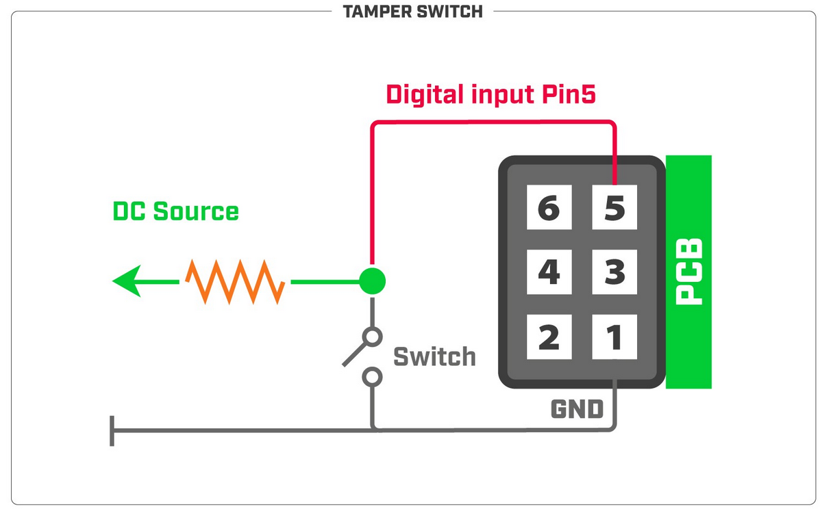
note: Digital input voltage is 0-2.5 V max.
...