Documentation
This document describes RouterOS, the operating system of MikroTik devices.
While the documentation is still being migrated, many additional articles are located in our old documentation portal..
|
Confluence Syndication Feed |
|||||||||||||||||||||||||||||||||||||||||||||||||||||||||||||||||||||||||||||||||||||||||||||||||||||||||||||||||||||||||||||||||||||||||||||||||||||||||||||||||||||||||||||||||||||||||||||||||||||||||||||||||||||||||||||||||||||||||||||||||||||||||||||||||||||||||||||||||||||||||||||||||||||||||||||||||||||||||||||||||||||||||||||||||||||||||||||||||||||||||||||||||||||||||||||||||||||||||||||||||||||||||||||||||||||||||||||||||||||||||||||||||||||||||||||||||||||||||||||||||||||||||||||||||||||||||||||||||||||||||||||||||||||||||||||||||||||||||||||||||||||||||||||||||||||||||||||||||||||||||||||||||||||||||||||||||||||||||||||||||||||||||||||||||||||||||||||||||||||||||||||||||||||||||||||||||||||||||||||||||||||||||||||||||||||||||||||||||||||||||||||||||||||||||||||||||||||||||||||||||||||||||||||||||||||||||||||||||||||||||||||||||||||||||||||||||||||||||||||||||||||||||||||||||||||||||||||||||||||||||||||||||||||||||||||||||||||||||||||||||||||||||||||||||||||||||||||||||||||||
|---|---|---|---|---|---|---|---|---|---|---|---|---|---|---|---|---|---|---|---|---|---|---|---|---|---|---|---|---|---|---|---|---|---|---|---|---|---|---|---|---|---|---|---|---|---|---|---|---|---|---|---|---|---|---|---|---|---|---|---|---|---|---|---|---|---|---|---|---|---|---|---|---|---|---|---|---|---|---|---|---|---|---|---|---|---|---|---|---|---|---|---|---|---|---|---|---|---|---|---|---|---|---|---|---|---|---|---|---|---|---|---|---|---|---|---|---|---|---|---|---|---|---|---|---|---|---|---|---|---|---|---|---|---|---|---|---|---|---|---|---|---|---|---|---|---|---|---|---|---|---|---|---|---|---|---|---|---|---|---|---|---|---|---|---|---|---|---|---|---|---|---|---|---|---|---|---|---|---|---|---|---|---|---|---|---|---|---|---|---|---|---|---|---|---|---|---|---|---|---|---|---|---|---|---|---|---|---|---|---|---|---|---|---|---|---|---|---|---|---|---|---|---|---|---|---|---|---|---|---|---|---|---|---|---|---|---|---|---|---|---|---|---|---|---|---|---|---|---|---|---|---|---|---|---|---|---|---|---|---|---|---|---|---|---|---|---|---|---|---|---|---|---|---|---|---|---|---|---|---|---|---|---|---|---|---|---|---|---|---|---|---|---|---|---|---|---|---|---|---|---|---|---|---|---|---|---|---|---|---|---|---|---|---|---|---|---|---|---|---|---|---|---|---|---|---|---|---|---|---|---|---|---|---|---|---|---|---|---|---|---|---|---|---|---|---|---|---|---|---|---|---|---|---|---|---|---|---|---|---|---|---|---|---|---|---|---|---|---|---|---|---|---|---|---|---|---|---|---|---|---|---|---|---|---|---|---|---|---|---|---|---|---|---|---|---|---|---|---|---|---|---|---|---|---|---|---|---|---|---|---|---|---|---|---|---|---|---|---|---|---|---|---|---|---|---|---|---|---|---|---|---|---|---|---|---|---|---|---|---|---|---|---|---|---|---|---|---|---|---|---|---|---|---|---|---|---|---|---|---|---|---|---|---|---|---|---|---|---|---|---|---|---|---|---|---|---|---|---|---|---|---|---|---|---|---|---|---|---|---|---|---|---|---|---|---|---|---|---|---|---|---|---|---|---|---|---|---|---|---|---|---|---|---|---|---|---|---|---|---|---|---|---|---|---|---|---|---|---|---|---|---|---|---|---|---|---|---|---|---|---|---|---|---|---|---|---|---|---|---|---|---|---|---|---|---|---|---|---|---|---|---|---|---|---|---|---|---|---|---|---|---|---|---|---|---|---|---|---|---|---|---|---|---|---|---|---|---|---|---|---|---|---|---|---|---|---|---|---|---|---|---|---|---|---|---|---|---|---|---|---|---|---|---|---|---|---|---|---|---|---|---|---|---|---|---|---|---|---|---|---|---|---|---|---|---|---|---|---|---|---|---|---|---|---|---|---|---|---|---|---|---|---|---|---|---|---|---|---|---|---|---|---|---|---|---|---|---|---|---|---|---|---|---|---|---|---|---|---|---|---|---|---|---|---|---|---|---|---|---|---|---|---|---|---|---|---|---|---|---|---|---|---|---|---|---|---|---|---|---|---|---|---|---|---|---|---|---|---|---|---|---|---|---|---|---|---|---|---|---|---|---|---|---|---|---|---|---|---|---|---|---|---|---|---|---|---|---|---|---|---|---|---|---|---|---|---|---|---|---|---|---|---|---|---|---|---|---|---|---|---|---|---|---|---|---|---|---|---|---|---|---|---|---|---|---|---|---|---|---|---|---|---|---|---|---|---|---|---|---|---|---|---|---|---|---|---|---|---|---|---|---|---|---|---|---|---|---|---|---|---|---|---|---|---|---|---|---|---|---|---|---|---|---|---|---|---|---|---|---|---|---|---|---|---|---|---|---|---|---|---|---|---|---|---|---|---|---|---|---|---|---|---|---|---|---|---|---|---|---|---|---|---|---|---|---|---|---|---|---|---|---|---|---|---|---|---|---|---|---|---|---|---|---|---|---|---|---|---|---|---|---|---|---|---|---|---|---|---|---|---|---|---|---|---|---|---|---|---|---|---|---|---|---|---|---|---|---|---|---|---|---|---|---|---|---|---|---|---|---|---|---|---|---|---|---|---|---|---|---|---|---|---|---|---|---|---|---|---|---|---|---|---|---|---|---|---|---|---|---|---|---|---|---|---|---|---|---|---|---|---|---|---|---|---|---|---|---|---|---|---|---|---|---|---|---|---|---|---|---|
|
RouterOS license keys
Page edited by Olga Ļ. OverviewMikroTik hardware routers that run RouterOS come preinstalled with a RouterOS license, if you have purchased a RouterOS based device, nothing must be done regarding the license. For X86 systems (i.e. PC devices), you need to obtain a license key. The license key is a block of symbols that needs to be copied from your mikrotik.com account, or from the email you received in, and then it can be pasted into the router. You can paste the key anywhere in the terminal, or by clicking "Paste key" in WinBox License menu. A reboot is required for the key to take effect. RouterOS licensing scheme is based on Software-ID / System-ID where:
Before the license purchase it is recommended to check if the software ID does not change on reboot. (Software ID may change on defective HDD, on HDD where RAID controllers are used but not properly configured etc.) Licensing information can be read from CLI system console: [admin@RB1100] > /system license print
software-id: "43NU-NLT9"
nlevel: 6
features:
[admin@RB1100] > or from equivalent WinBox, WebFig menu.
License LevelsAfter installation RouterOS runs in trial mode. You have 24 hours to register for Level1 (Free demo) or purchase a Level 4,5 or 6 license and paste a valid key. Level 3 is a wireless station (client or CPE) only license. For x86 PCs, Level3 is not available for purchase individually. Level 2 was a transitional license from old legacy (pre 2.8) license format. These licenses are not available any more, if you have this kind of license, it will work, but to upgrade it - you will have to purchase a new license. The difference between license levels is shown in the table below.
All Licenses:
CHR License LevelsLicense levels described until now do not apply to Cloud Hosted Routers (CHRs). CHR is a RouterOS version intended for running as a virtual machine. It has its own 4 license levels as well as trial where you can test any of the paid license levels for 60 days. 60-day free trial license is available for all paid license levels. To get the free trial license, you have to have an account on MikroTik.com as all license management is done there. Perpetual is a lifetime license (buy once, use forever). It is possible to transfer a perpetual license to another CHR instance. A running CHR instance will indicate the time when it has to access the account server to renew it's license. If the CHR instance will not be able to renew the license it will behave as if the trial period has ran out and will not allow an upgrade of RouterOS to a newer version. After licensing a running trial system, you must manually run the
Warning: If you plan to use multiple virtual systems of the same kind, it may be possible that the next machine has the same SystemID as the original one. This can happen on certain cloud providers, such as Linode. To avoid this, after your first boot, run the command " To use multiple virtual machines, download the disk image from our webpage, and make as many copies, as you need virtual machines. Then make new virtual machine system from each virtual disk image. Make sure to make copies of the Disk Image before you run or register the downloaded file. Replacement KeyIt is a special key which is issued by the MikroTik support team if you accidentally lose the license on a x86 instance running RouterOS, and the MikroTik Support employee decides that it is not directly your fault. It costs 10$ and has the same features as the key that you lost. Note that before issuing such key, MikroTik Support can ask you to prove that the old drive has failed, in some cases, this means sending us the dead drive. Replacement key request1) Go to your account management in mikrotik.com and fill the "support contact form" or write a direct e-mail to support@mikrotik.com
2) Send required info to MikroTik support department. 3) Re-check your account after support staff has confirmed that replacement key has been added to your account. Select the section "Make a key from replacement key"
4) Select the appropriate license level on which you wish to perform the replacement 5) Enter the new "software-ID" 6) Proceed to checkout by pressing "Add license replacement to cart" and finish the payment
7) An e-mail will be sent to your profile containing the new license.
We may issue only one replacement key per one original key, using replacement key procedure twice for one key will not be possible. In cases like this new key for this RouterOS device must be purchased. Obtaining Licenses and Working With ThemWhere can I buy a RouterOS license key?MikroTik devices come preinstalled with a license and no purchase is needed. To obtain a higher level license, or to obtain a license for a x86 PC installation, you must register an account on our webpage, and in there, use the option "Purchase a RouterOS license key". If I have purchased my key elsewhereYou must contact the company who sold you the license, they will provide the support. If I have a license and want to put it on another account?You can give access to keys with the help of Virtual Folders The only kind of licenses, that could be transferred to another Account is a prepaid key, which is purchased or is got from MUM. Prepaid keys got as a gift from the Training are not transferable. If I have lost a license on my device?If for some reason you have lost license from your router, upgrade router to the latest RouterOS version available and use "Request license key" in your mikrotik.com account. Use soft-id and serial number available under System/License menu in RouterOS when requesting license. Apply received license or contact support@mikrotik.com if request feature do not work. If the license was lost due to repairs and they were not done via the distributor under warranty, you will have to purchase a new RouterOS license for the full price! Using the LicenseCan I Format or Re-Flash the drive?Formatting, and Re-Imaging the drive with non-MikroTik tools (like DD and Fdisk) will destroy your license! Be very careful and contact MikroTik support before doing this. It is not recommended, as MikroTik support might deny your request for a replacement license. For this use MikroTik provided tools - Netinstall or CD-install that are freely available from our download page. How many computers can I use the License on?The RouterOS license can be used only in one system, at the same time. The License is bound to the HDD it is installed on, but you have the ability to move the HDD to another computer system. You cannot move the License to another HDD, neither can you format or overwrite the HDD with the RouterOS license. It will be erased from the drive, and you will have to get a new one. If you accidentally removed your license, contact the support team for help. Can I temporary use the HDD for something else, other than RouterOS?As stated above, no. Can I move the license to another HDD ?If your current HDD drive is destroyed, or can no longer be used, it is possible to transfer the license to another HDD. You will have to request a replacement key (see below) which will cost 10$ Must I type the whole key into the router?No, simply copy it and paste in the menu System --> License,
Can I install another OS on my drive and then install RouterOS again later?No, because if you use formatting, partitioning utilities or tools that do something to the MBR, you will lose the license and you will have to make a new one. This process is not free (see Replacement Key above) I lost my RouterBOARD, can you give me the license to use on another system?MikroTik hardware comes with an embedded license. You cannot move this license to a new system in any way, this includes any upgrades applied to the MikroTik router while it was still working. Licenses Purchased from ResellersThe keys that you purchase from other vendors and resellers are not in your account. Your mikrotik.com account only contains licenses purchased from MikroTik directly. However, you can use the "Request key" link in your account, to get the key into your account for reference, or for some upgrades (if available). I am not using the software, can you terminate my license? The licenses are stand alone keys and MikroTik does not have any remote control over your devices. Therefore, we are unable to verify if you use your license or not. This is why MikroTik cannot terminate any issued licenses. |
|||||||||||||||||||||||||||||||||||||||||||||||||||||||||||||||||||||||||||||||||||||||||||||||||||||||||||||||||||||||||||||||||||||||||||||||||||||||||||||||||||||||||||||||||||||||||||||||||||||||||||||||||||||||||||||||||||||||||||||||||||||||||||||||||||||||||||||||||||||||||||||||||||||||||||||||||||||||||||||||||||||||||||||||||||||||||||||||||||||||||||||||||||||||||||||||||||||||||||||||||||||||||||||||||||||||||||||||||||||||||||||||||||||||||||||||||||||||||||||||||||||||||||||||||||||||||||||||||||||||||||||||||||||||||||||||||||||||||||||||||||||||||||||||||||||||||||||||||||||||||||||||||||||||||||||||||||||||||||||||||||||||||||||||||||||||||||||||||||||||||||||||||||||||||||||||||||||||||||||||||||||||||||||||||||||||||||||||||||||||||||||||||||||||||||||||||||||||||||||||||||||||||||||||||||||||||||||||||||||||||||||||||||||||||||||||||||||||||||||||||||||||||||||||||||||||||||||||||||||||||||||||||||||||||||||||||||||||||||||||||||||||||||||||||||||||||||||||||||||||
|
User
Page edited by Serhii T. SummaryMikroTik RouterOS router user facility manages the users connecting the router from any of the Management tools. The users are authenticated using either a local database or a designated RADIUS server. Each user is assigned to a user group, which denotes the rights of this user. A group policy is a combination of individual policy items. In case the user authentication is performed using RADIUS, the RADIUS client should be previously configured. User SettingsThe settings submenu allows to control the password complexity requirements of the router users.
User GroupsThe router user groups provide a convenient way to assign different permissions and access rights to different user classes. Properties
Default groupsThere are three default system groups which cannot be deleted: [admin@MikroTik] > /user group print 0 name="read" policy=local,telnet,ssh,reboot,read,test,winbox,password,web,sniff,sensitive,api,romon,tikapp,!ftp,!write,!policy,!dude skin=default 1 name="write" policy=local,telnet,ssh,reboot,read,write,test,winbox,password,web,sniff,sensitive,api,romon,tikapp,!ftp,!policy,!dude skin=default 2 name="full" policy=local,telnet,ssh,ftp,reboot,read,write,policy,test,winbox,password,web,sniff,sensitive,api,romon,tikapp,!dude skin=default Please note, that even the "read" group includes sensitive, reboot, and other important policies, meaning that this group should not be given to untrusted users. For truly limited groups, make a custom group, defining specific policies. All groups have access to file operations. Exclamation sign '!' just before the policy item name means NOT. Router UsersThe router user database stores information such as username, password, allowed access addresses, and group about router management personnel. Properties
ActionsActions for existing router user.
NotesThere is one predefined user with full access rights: [admin@MikroTik] user> print Flags: X - disabled # NAME GROUP ADDRESS LAST-LOGGED-IN 0 ;;; system default user admin full 0.0.0.0/0 dec/08/2010 16:19:24 There always should be at least one user with full access rights. If the user with full access rights is the only one, it cannot be removed. Monitoring Active Users/user active print The command shows the currently active users along with respective statistics information. PropertiesAll properties are read-only.
Remote AAARouter user remote AAA enables router user authentication and accounting via a RADIUS server. The RADIUS user database is consulted only if the required username is not found in the local user database. Properties
If you are using RADIUS, you need to have CHAP support enabled in the RADIUS server for WinBox to work SSH KeysThis menu allows importing of private and public keys used for SSH authentication. By default, User is not allowed to log in via SSH by password if an SSH key for the user is added. For more details see the SSH page. Public keysThis menu is used to import and list imported public keys. Public keys are used to approve another device's identity when logging into a router using an SSH key. On public key import, is it possible to specify key-owner. RSA and Ed25519 keys are supported in PEM, PKCS#8, or OpenSSH format.
Private keysThis menu is used to import and list imported private keys. Private keys are used to approve the router's identity during login into another device using an SSH key. On private key import, is it possible to specify key-owner. RSA and Ed25519 keys are supported in PEM or PKCS#8 format.
|
|||||||||||||||||||||||||||||||||||||||||||||||||||||||||||||||||||||||||||||||||||||||||||||||||||||||||||||||||||||||||||||||||||||||||||||||||||||||||||||||||||||||||||||||||||||||||||||||||||||||||||||||||||||||||||||||||||||||||||||||||||||||||||||||||||||||||||||||||||||||||||||||||||||||||||||||||||||||||||||||||||||||||||||||||||||||||||||||||||||||||||||||||||||||||||||||||||||||||||||||||||||||||||||||||||||||||||||||||||||||||||||||||||||||||||||||||||||||||||||||||||||||||||||||||||||||||||||||||||||||||||||||||||||||||||||||||||||||||||||||||||||||||||||||||||||||||||||||||||||||||||||||||||||||||||||||||||||||||||||||||||||||||||||||||||||||||||||||||||||||||||||||||||||||||||||||||||||||||||||||||||||||||||||||||||||||||||||||||||||||||||||||||||||||||||||||||||||||||||||||||||||||||||||||||||||||||||||||||||||||||||||||||||||||||||||||||||||||||||||||||||||||||||||||||||||||||||||||||||||||||||||||||||||||||||||||||||||||||||||||||||||||||||||||||||||||||||||||||||||||
|
WiFi
Page edited by Guntis G.
OverviewThe 'WiFi' configuration menu, introduced in RouterOS 7.13, is a RouterOS menu for managing Wi-Fi 5 wave2 and newer WiFi interfaces. Devices with compatible radios also require either the 'wifi-qcom-ac' driver package (for 802.11ac chipsets) or the 'wifi-qcom' driver package for 802.11ax and newer chipsets. The configuration menu used to be called 'wifiwave2' in RouterOS versions before 7.13, where it was a part of the 'wifiwave2' software package. WiFi TerminologyBefore we move on let's familiarize ourselves with terms important for understanding the operation of the menu. These terms will be used throughout the article.
Basic ConfigurationBasic password-protected AP /interface/wifi set wifi1 disabled=no configuration.country=Latvia configuration.ssid=MikroTik security.authentication-types=wpa2-psk,wpa3-psk security.passphrase=8-63_characters Open AP with OWE transition mode Opportunistic wireless encryption (OWE) allows the creation of wireless networks that do not require the knowledge of a password to connect, but still offer the benefits of traffic encryption and management frame protection. It is an improvement on regular open access points. However, since a network cannot be simultaneously encrypted and unencrypted, 2 separate interface configurations are required to offer connectivity to older devices that do not support OWE and offer the benefits of OWE to devices that do. This configuration is referred to as OWE transition mode. /interface/wifi add master-interface=wifi1 name=wifi1_owe configuration.ssid=MikroTik_OWE security.authentication-types=owe security.owe-transition-interface=wifi1 configuration.hide-ssid=yes set wifi1 configuration.country=Latvia configuration.ssid=MikroTik security.authentication-types="" security.owe-transition-interface=wifi1_owe enable wifi1,wifi1_owe Client devices that support OWE will prefer the OWE interface. If you don't see any devices in your registration table that are associated with the regular open AP, you may want to move on from running a transition mode setup to a single OWE-encrypted interface. Resetting configuration WiFi interface configurations can be reset by using the 'reset' command. /interface/wifi reset wifi1 Configuration profilesOne of the new WiFi additions is configuration profiles, you can create various presets, that can be assigned to interfaces as needed. Configuration settings for WiFi are grouped in profiles according to the parameter sections found at the end of this page - aaa, channel, configuration, datapath, interworking, and security, and can then be assigned to interfaces. Configuration profiles can include other profiles as well as separate parameters from other categories. This optional flexibility is meant to allow each user to arrange their configuration in a way that makes the most sense for them, but it also means that each parameter may have different values assigned to it in different sections of the configuration. The following priority determines, which value is used:
If you are at any point unsure of which parameter value will be used for an interface, consult the actual-configuration menu. For an example of configuration profile usage, see the following example. Example for dual-band home AP # Creating a security profile, which will be common for both interfaces /interface wifi security add name=common-auth authentication-types=wpa2-psk,wpa3-psk passphrase="diceware makes good passwords" wps=disable # Creating a common configuration profile and linking the security profile to it /interface wifi configuration add name=common-conf ssid=MikroTik country=Latvia security=common-auth # Creating separate channel configurations for each band /interface wifi channel add name=ch-2ghz frequency=2412,2432,2472 width=20mhz add name=ch-5ghz frequency=5180,5260,5500 width=20/40/80mhz # Assigning to each interface the common profile as well as band-specific channel profile /interface wifi set wifi1 channel=ch-2ghz configuration=common-conf disabled=no set wifi2 channel=ch-5ghz configuration=common-conf disabled=no /interface/wifi/actual-configuration print 0 name="wifi1" mac-address=74:4D:28:94:22:9A arp-timeout=auto radio-mac=74:4D:28:94:22:9A configuration.ssid="MikroTik" .country=Latvia security.authentication-types=wpa2-psk,wpa3-psk .passphrase="diceware makes good passwords" .wps=disable channel.frequency=2412,2432,2472 .width=20mhz 1 name="wifi2" mac-address=74:4D:28:94:22:9B arp-timeout=auto radio-mac=74:4D:28:94:22:9B configuration.ssid="MikroTik" .country=Latvia security.authentication-types=wpa2-psk,wpa3-psk .passphrase="diceware makes good passwords" .wps=disable channel.frequency=5180,5260,5500 .width=20/40/80mhz Access ListThe access list provides multiple ways of filtering and managing wireless connections. RouterOS will check each new connection to see if its parameters match the parameters specified in any access list rule. The rules are checked in the order they appear in the list. Only management actions specified in the first matching rule are applied to each connection. Connections, which have been accepted by an access list rule, will be periodically checked, to see if they remain within the permitted time and signal-range. If they do not, they will be terminated. Take care when writing access list rules which reject clients. After being repeatedly rejected by an AP, a client device may start avoiding it. The access list has two kinds of parameters - filtering, and action. Filtering properties are only used for matching clients, to whom the access list rule should be applied to. Action parameters can change connection parameters for that specific client and potentially overriding its default connection parameters with ones specified in the access list rule. MAC address authenticationImplemented through the query-radius action, MAC address authentication is a way to implement a centralized whitelist of client MAC addresses using a RADIUS server. When a client device tries to associate with an AP, which is configured to perform MAC address authentication, the AP will send an access-request message to a RADIUS server with the device's MAC address as the user name and an empty password. If the RADIUS server answers with access-accept to such a request, the AP proceeds with whatever regular authentication procedure (passphrase or EAP authentication) is configured for the interface. Access rule examplesOnly accept connections to guest network from nearby devices during business hours /interface/wifi/access-list/print detail Flags: X - disabled 0 signal-range=-60..0 allow-signal-out-of-range=5m ssid-regexp="MikroTik Guest" time=7h-19h,mon,tue,wed,thu,fri action=accept 1 ssid-regexp="MikroTik Guest" action=reject Reject connections from locally-administered ('anonymous'/'randomized') MAC addresses /interface/wifi/access-list/print detail Flags: X - disabled 0 mac-address=02:00:00:00:00:00 mac-address-mask=02:00:00:00:00:00 action=reject Assigning a different passphrase for a specific client can be useful, if you need to provide wireless access to a client, but don't want to share your wireless password, or don't want to create a separate SSID. When the matching client connects to this network, instead of using the password defined in the interface configuration, the access list will make that client use a different password. Just make sure that the specific client doesn't get matched by a more generic access list rule first. /interface wifi access-list add action=accept disabled=no mac-address=22:F9:70:E5:D2:8E interface=wifi1 passphrase=StrongPassword Frequency scanThe '/interface/wifi/frequency-scan wifi1' command provides information about RF conditions on available channels that can be obtained by running the frequency-scan command. Used to approximate the spectrum usage, it can be useful to find less crowded frequencies.
Running a frequency scan will disconnect all connected clients, or if the interface is in station mode, it will disconnect from AP. Scan commandThe '/interface wifi scan' command will scan for access points and print out information about any APs it detects. It doesn't show the frequency usage, per channel, but it will reveal all access points that are transmitting. You can use the "connect" button, to initiate a connection to a specific AP. The scan command takes all the same parameters as the frequency-scan command.
SnifferThe sniffer command enables monitor mode on a wireless interface. This turns the interface into a passive receiver for all WiFi transmissions. The sniffer will operate on whichever channel is configured for the chosen interface.
Spectral scanThe spectral scan can scan frequencies supported by your wifi interface, and plot them directly in the console. The spectral scan has been available since the 7.16beta1 version. Spectral scan is supported only by the wifi-qcom driver, it is not supported by the wifi-qcom-ac driver. /interface/wifi/spectral-scan <wifiinterface name> range=
To use spectral scan, you must use the "range=" attribute. Each line displays one spectrogram bucket -- frequency, magnitude (dBm), peak, and a character graphic bar. A bar shows power value with ':' characters and average peak hold with '.' characters.
Possible types of classified interference:
Spectral history/interface/wifi/spectral-history <wifi interface name> range=
Possible types of classified interference:
WPSWPS clientThe wps-client command enables obtaining authentication information from a WPS-enabled AP. /interface/wifi/wps-client wifi1 WPS serverAn AP can be made to accept WPS authentication by a client device for 2 minutes by running the following command. /interface/wifi wps-push-button wifi1 RadiosInformation about the capabilities of each radio can be gained by running the `/interface/wifi/radio print detail` command. It can be useful to see what bands are supported by the interface and what channels can be selected. The country profile that is applied to the interface will influence the results. interface/wifi/radio/print detail
Flags: L - local
0 L radio-mac=48:A9:8A:0B:F7:4A phy-id=0 tx-chains=0,1 rx-chains=0,1
bands=5ghz-a:20mhz,5ghz-n:20mhz,20/40mhz,5ghz-ac:20mhz,20/40mhz,20/40/80mhz,5ghz-ax:20mhz,
20/40mhz,20/40/80mhz
ciphers=tkip,ccmp,gcmp,ccmp-256,gcmp-256,cmac,gmac,cmac-256,gmac-256 countries=all
5g-channels=5180,5200,5220,5240,5260,5280,5300,5320,5500,5520,5540,5560,5580,5600,5620,5640,5660,
5680,5700,5720,5745,5765,5785,5805,5825
max-vlans=128 max-interfaces=16 max-station-interfaces=3 max-peers=120 hw-type="QCA6018"
hw-caps=sniffer interface=wifi1 current-country=Latvia
current-channels=5180/a,5180/n,5180/n/Ce,5180/ac,5180/ac/Ce,5180/ac/Ceee,5180/ax,5180/ax/Ce,
5180/ax/Ceee,5200/a,5200/n,5200/n/eC,5200/ac,5200/ac/eC,5200/ac/eCee,5200/ax...
...5680/n/eC,5680/ac,5680/ac/eC,5680/ax,5680/ax/eC,5700/a,5700/n,5700/ac,5700/ax
current-gopclasses=115,116,128,117,118,119,120,121,122,123 current-max-reg-power=30 While Radio information gives us information about supported channel width, it is also possible to deduce this information from the product page, to do so you need to check the following parameters: number of chains, max data rate. Once you know these parameters, you need to check the modulation and coding scheme (MCS) table, for example, here: https://mcsindex.com/. If we take hAP ax2, as an example, we can see that number of chains is 2, and the max data rate is 1200 - 1201 in the MCS table. In the MCS table we need to find entry for 2 spatial streams - chains, and the respective data rate, which in this case shows us that 80MHz is the maximum supported channel width. Registration table'/interface/wifi/registration-table/' displays a list of connected wireless clients and detailed information about them.
De-authenticationWireless peers can be manually de-authenticated (forcing re-association) by removing them from the registration table. /interface/wifi/registration-table remove [find where mac-address=02:01:02:03:04:05] WiFi CAPsMANWiFi CAPsMAN allows applying wireless settings to multiple MikroTik WiFi AP devices from a central configuration interface. More specifically, the Controlled Access Point system Manager (CAPsMAN) allows the centralization of wireless network management. When using the CAPsMAN feature, the network will consist of a number of 'Controlled Access Points' (CAP) that provide wireless connectivity and a 'system Manager' (CAPsMAN) that manages the configuration of the APs, it also takes care of client authentication. WiFi CAPsMAN only passes wireless configuration to the CAP, all forwarding decisions are left to the CAP itself - there is no CAPsMAN forwarding mode. Requirements:
WiFi CAPsMAN can only control WiFi interfaces, and WiFi CAPs can join only WiFi CAPsMAN, similarly, regular CAPsMAN only supports non-WiFi caps. The CAPs don't send traffic usage information to CAPsMAN. CAPsMAN - CAP simple configuration example:CAPsMAN in WiFi uses the same menu as a regular WiFi interface, meaning when you pass configuration to CAPs, you have to use the same configuration, security, channel configuration, etc. as you would for regular WiFi interfaces. You can configure sub-configuration menus, directly under "/interface/wifi/configuration" or reference previously created profiles in the main configuration profile CAPsMAN: #create a security profile
/interface wifi security
add authentication-types=wpa3-psk name=sec1 passphrase=HaveAg00dDay
#create configuraiton profiles to use for provisioning
/interface wifi configuration
add country=Latvia name=5ghz security=sec1 ssid=CAPsMAN_5
add name=2ghz security=sec1 ssid=CAPsMAN2
add country=Latvia name=5ghz_v security=sec1 ssid=CAPsMAN5_v
#configure provisioning rules, configure band matching as needed
/interface wifi provisioning
add action=create-dynamic-enabled master-configuration=5ghz slave-configurations=5ghz_v supported-bands=\
5ghz-n
add action=create-dynamic-enabled master-configuration=2ghz supported-bands=2ghz-n
#enable CAPsMAN service
/interface wifi capsman
set ca-certificate=auto enabled=yes CAP: #enable CAP service, in this case CAPsMAN is on same LAN, but you can also specify "caps-man-addresses=x.x.x.x" here /interface/wifi/cap set enabled=yes #set configuration.manager= on the WiFi interface that should act as CAP /interface/wifi/set wifi1,wifi2 configuration.manager=capsman-or-local If the CAP is hAP ax2 or hAP ax3, it is strongly recommended to enable RSTP in the bridge configuration, on the CAP configuration.manager should only be set on the CAP device itself, don't pass it to the CAP or configuration profile that you provision. The interface that should act as CAP needs additional configuration under "interface/wifi/set wifiX configuration.manager=" CAPsMAN - CAP VLAN configuration example:In this example, we will assign VLAN10 to our main SSID, and will add VLAN20 for the guest network, ether5 from CAPsMAN is connected to CAP. CAPs using "wifi-qcom" package can get "vlan-id" via Datapath from CAPsMAN, CAPs using "wifi-qcom-ac" package will need to use the configuration provided at the end of this example. CAPsMAN:/interface bridge add name=br vlan-filtering=yes /interface vlan add interface=br name=MAIN vlan-id=10 add interface=br name=GUEST vlan-id=20 /interface wifi datapath add bridge=br name=MAIN vlan-id=10 add bridge=br name=GUEST vlan-id=20 /interface wifi security add authentication-types=wpa2-psk,wpa3-psk ft=yes ft-over-ds=yes name=Security_MAIN passphrase=HaveAg00dDay add authentication-types=wpa2-psk,wpa3-psk ft=yes ft-over-ds=yes name=Security_GUEST passphrase=HaveAg00dDay /interface wifi configuration add datapath=MAIN name=MAIN security=Security_MAIN ssid=MAIN_Network add datapath=GUEST name=GUEST security=Security_GUEST ssid=GUEST_Network /ip pool add name=dhcp_pool0 ranges=192.168.1.2-192.168.1.254 add name=dhcp_pool1 ranges=192.168.10.2-192.168.10.254 add name=dhcp_pool2 ranges=192.168.20.2-192.168.20.254 /ip dhcp-server add address-pool=dhcp_pool0 disabled=yes interface=br name=dhcp1 add address-pool=dhcp_pool1 interface=MAIN name=dhcp2 add address-pool=dhcp_pool2 interface=GUEST name=dhcp3 /interface bridge port add bridge=br interface=ether5 add bridge=br interface=ether4 add bridge=br interface=ether3 add bridge=br interface=ether2 /interface bridge vlan add bridge=br tagged=br,ether5,ether4,ether3,ether2 vlan-ids=20 add bridge=br tagged=br,ether5,ether4,ether3,ether2 vlan-ids=10 /interface wifi capsman set enabled=yes interfaces=br /interface wifi provisioning add action=create-dynamic-enabled master-configuration=MAIN slave-configurations=GUEST supported-bands=5ghz-ax add action=create-dynamic-enabled master-configuration=MAIN slave-configurations=GUEST supported-bands=2ghz-ax /ip address add address=192.168.1.1/24 interface=br network=192.168.1.0 add address=192.168.10.1/24 interface=MAIN network=192.168.10.0 add address=192.168.20.1/24 interface=GUEST network=192.168.20.0 /ip dhcp-server network add address=192.168.1.0/24 gateway=192.168.1.1 add address=192.168.10.0/24 gateway=192.168.10.1 add address=192.168.20.0/24 gateway=192.168.20.1 /system identity set name=cAP_Controller CAP using "wifi-qcom" package:/interface bridge add name=bridgeLocal /interface wifi datapath add bridge=bridgeLocal comment=defconf disabled=no name=capdp /interface wifi set [ find default-name=wifi1 ] configuration.manager=capsman datapath=capdp disabled=no set [ find default-name=wifi2 ] configuration.manager=capsman datapath=capdp disabled=no /interface bridge port add bridge=bridgeLocal comment=defconf interface=ether1 add bridge=bridgeLocal comment=defconf interface=ether2 add bridge=bridgeLocal comment=defconf interface=ether3 add bridge=bridgeLocal comment=defconf interface=ether4 add bridge=bridgeLocal comment=defconf interface=ether5 /interface wifi cap set discovery-interfaces=bridgeLocal enabled=yes slaves-datapath=capdp /ip dhcp-client add interface=bridgeLocal disabled=no CAP using "wifi-qcom-ac" package:/interface bridge add name=bridgeLocal vlan-filtering=yes /interface wifi set [ find default-name=wifi1 ] configuration.manager=capsman disabled=no set [ find default-name=wifi2 ] configuration.manager=capsman disabled=no add disabled=no master-interface=wifi1 name=wifi21 add disabled=no master-interface=wifi2 name=wifi22 /interface bridge port add bridge=bridgeLocal comment=defconf interface=ether1 add bridge=bridgeLocal comment=defconf interface=ether2 add bridge=bridgeLocal comment=defconf interface=ether3 add bridge=bridgeLocal comment=defconf interface=ether4 add bridge=bridgeLocal comment=defconf interface=ether5 add bridge=bridgeLocal interface=wifi1 pvid=10 add bridge=bridgeLocal interface=wifi21 pvid=20 add bridge=bridgeLocal interface=wifi2 pvid=10 add bridge=bridgeLocal interface=wifi22 pvid=20 /interface bridge vlan add bridge=bridgeLocal tagged=ether1 untagged=wifi1,wifi2 vlan-ids=10 add bridge=bridgeLocal tagged=ether1 untagged=wifi21,wifi22 vlan-ids=20 /interface wifi cap set discovery-interfaces=bridgeLocal enabled=yes slaves-static=yes Additionally, the configuration below has to be added to the CAPsMAN configuration: /interface wifi datapath add bridge=br name=DP_AC /interface wifi configuration add datapath=DP_AC name=MAIN_AC security=Security_MAIN ssid=MAIN_Network add datapath=DP_AC name=GUEST_AC security=Security_GUEST ssid=GUEST_Network /interface wifi provisioning add action=create-dynamic-enabled master-configuration=MAIN_AC slave-configurations=GUEST_AC supported-bands=5ghz-ac add action=create-dynamic-enabled master-configuration=MAIN_AC slave-configurations=GUEST_AC supported-bands=2ghz-n Passing datapaths "MAIN/GUEST" from the start of the example to "wifi-qcom-ac" CAP would be misconfiguration, make sure to use datapath without "vlan-id" specified to such devices. Advanced examplesReplacing 'wireless' packageSome MikroTik Wi-Fi 5 APs, which ship with their interfaces managed by the 'wireless' menu, can install the additional 'wifi-qcom-ac' package to make their interfaces compatible with the 'wifi' menu instead. To do this, it is necessary to uninstall the 'wireless' package, then install 'wifi-qcom-ac'. CompatibilityThe wifi-qcom-ac package includes alternative drivers for IPQ4018/4019 and QCA9984 radios that make them compatible with the WiFi configuration menu. For possible, wifi-qcom-ac/wifi-qcom/wireless, package combinations, please see the package types section here. As a rule of thumb, the package is compatible with 802.11ac products, which have an ARM CPU. It is NOT compatible with any of our 802.11ac products which have a MIPS CPU.
Benefits
These benefits apply both to the wifi-qcom and wifi-qcom-ac packages. Lost featuresThe following notable features are lost when running 802.11ac products with drivers that are compatible with the 'wifi' management interface
Property ReferenceAAA propertiesProperties in this category configure an access point's interaction with AAA (RADIUS) servers. Certain parameters in the table below take format-string as their value. In a format-string, certain characters are interpreted in the following way:
All other characters are used without interpreting them in any way. For examples, see default values.
Channel propertiesProperties in this category specify the desired radio channel.
Configuration propertiesThis section includes properties relating to the operation of the interface and the associated radio.
Datapath propertiesParameters relating to forwarding packets to and from wireless client devices.
Security PropertiesParameters relating to authentication.
Steering propertiesProperties in this category govern mechanisms for advertising potential roaming candidates to client devices.
Miscellaneous properties
Read-only properties
Access List
Frequency scanInformation about RF conditions on available channels can be obtained by running the frequency-scan command.
Flat-snoopThe '/interface wifi flat-snoop' is a tool for surveying APs and stations. Monitors frequency usage, and displays which devices occupy each frequency. Provides more detailed infromation regarding nearby APs than scan, and offers easy overview of frequency usage by station/AP count.
Scan commandThe '/interface wifi scan' command will scan for access points and print out information about any APs it detects. The scan command takes all the same parameters as the frequency-scan command.
Sniffer
WPSinterface/wifi/wps-client wifi
RadiosInformation about the capabilities of each radio can be gained by running the `/interface/wifi/radio print detail` command.
Registration tableThe registration table contains read-only information about associated wireless devices.
CAPsMAN Global ConfigurationMenu: /interface/wifi/capsman
CAPsMAN ProvisioningProvisioning rules for matching radios are configured in /interface/wifi/provisioning/ menu:
CAP configurationMenu: /interface/wifi/cap
|
|||||||||||||||||||||||||||||||||||||||||||||||||||||||||||||||||||||||||||||||||||||||||||||||||||||||||||||||||||||||||||||||||||||||||||||||||||||||||||||||||||||||||||||||||||||||||||||||||||||||||||||||||||||||||||||||||||||||||||||||||||||||||||||||||||||||||||||||||||||||||||||||||||||||||||||||||||||||||||||||||||||||||||||||||||||||||||||||||||||||||||||||||||||||||||||||||||||||||||||||||||||||||||||||||||||||||||||||||||||||||||||||||||||||||||||||||||||||||||||||||||||||||||||||||||||||||||||||||||||||||||||||||||||||||||||||||||||||||||||||||||||||||||||||||||||||||||||||||||||||||||||||||||||||||||||||||||||||||||||||||||||||||||||||||||||||||||||||||||||||||||||||||||||||||||||||||||||||||||||||||||||||||||||||||||||||||||||||||||||||||||||||||||||||||||||||||||||||||||||||||||||||||||||||||||||||||||||||||||||||||||||||||||||||||||||||||||||||||||||||||||||||||||||||||||||||||||||||||||||||||||||||||||||||||||||||||||||||||||||||||||||||||||||||||||||||||||||||||||||||
|
L3 Hardware Offloading
Page edited by Ričards I. IntroductionLayer 3 Hardware Offloading (L3HW, otherwise known as IP switching or HW routing) allows to offload some router features onto the switch chip. This allows reaching wire speeds when routing packets, which would simply not be possible with the CPU. Switch ConfigurationTo enable Layer 3 Hardware Offloading, set /interface/ethernet/switch set 0 l3-hw-offloading=yes Switch Port ConfigurationLayer 3 Hardware Offloading can be configured for each physical switch port. For example: /interface/ethernet/switch/port set sfp-sfpplus1 l3-hw-offloading=yes Note that l3hw settings for switch and ports are different:
To enable full hardware routing, enable l3hw on all switch ports: /interface/ethernet/switch set 0 l3-hw-offloading=yes /interface/ethernet/switch/port set [find] l3-hw-offloading=yes To make all packets go through the CPU first, and offload only the Fasttrack connections, disable l3hw on all ports but keep it enabled on the switch chip itself: /interface/ethernet/switch set 0 l3-hw-offloading=yes /interface/ethernet/switch/port set [find] l3-hw-offloading=no Packets get routed by the hardware only if both source and destination ports have The next example enables hardware routing on all ports but the upstream port (sfp-sfpplus16). Packets going to/from sfp-sfpplus16 will enter the CPU and, therefore, subject to Firewall/NAT processing. /interface/ethernet/switch set 0 l3-hw-offloading=yes /interface/ethernet/switch/port set [find] l3-hw-offloading=yes /interface/ethernet/switch/port set sfp-sfpplus16 l3-hw-offloading=no The existing connections may be unaffected by the L3HW SettingsBasic SettingsThe L3HW Settings menu has been introduced in RouterOS version 7.6. Sub-menu:
Read-Only Properties
Advanced SettingsThis menu allows tweaking l3hw settings for specific use cases. It is NOT recommended to change the advanced L3HW settings unless instructed by MikroTik Support or MikroTik Certified Routing Engineer. Applying incorrect settings may break the L3HW operation. Sub-menu:
Some settings only apply to certain switch models. MonitorThe L3HW Monitor feature has been introduced in RouterOS version 7.10. It allows monitoring of switch chip and driver stats related to L3HW. /interface/ethernet/switch/l3hw-settings/monitor ipv4-routes-total: 99363 ipv4-routes-hw: 61250 ipv4-routes-cpu: 38112 ipv4-shortest-hw-prefix: 24 ipv4-hosts: 87 ipv6-routes-total: 15 ipv6-routes-hw: 11 ipv6-routes-cpu: 4 ipv6-shortest-hw-prefix: 0 ipv6-hosts: 7 route-queue-size: 118 fasttrack-ipv4-conns: 2031 fasttrack-hw-min-speed: 0 nexthop-cap: 8192 nexthop-usage: 93 Stats
1 IPv6 stats appear only when IPv6 hardware routing is enabled ( 2 FastTrack stats appear only when hardware offloading of FastTrack connections is enabled (fasttrack-hw Advanced MonitorAn enhanced version of Monitor with extra telemetry data for advanced users. Advanced Monitor contains all data from the basic monitor plus the fields listed below. /interface/ethernet/switch/l3hw-settings/advanced> monitor once ipv4-routes-total: 29968 ipv4-routes-hw: 29957 ipv4-routes-cpu: 11 ipv4-shortest-hw-prefix: 0 ipv4-hosts: 3 ipv6-routes-total: 4 ipv6-routes-hw: 0 ipv6-routes-cpu: 4 ipv6-shortest-hw-prefix: 0 ipv6-hosts: 0 route-queue-size: 0 route-queue-rate: 0 route-process-rate: 0 fasttrack-ipv4-conns: 0 fasttrack-queue-size: 0 fasttrack-queue-rate: 0 fasttrack-process-rate: 0 fasttrack-hw-min-speed: 0 fasttrack-hw-offloaded: 0 fasttrack-hw-unloaded: 0 lpm-cap: 54560 lpm-usage: 31931 lpm-bank-cap: 2728 lpm-bank-usage: 46,0,0,0,2589,2591,1983,0,2728,2728,2728,2728,2728,2728,2728,2728,2728,170,0,0 pbr-cap: 8192 pbr-usage: 0 pbr-lpm-bank: 3 nat-usage: 0 nexthop-cap: 8192 nexthop-usage: 85 Stats
Interface ListsIt is impossible to use interface lists directly to control However, an interface list may be used as a port selector. The following example demonstrates how to enable hardware routing on LAN ports (ports that belong to the "LAN" interface list) and disable it on WAN ports: :foreach i in=[/interface/list/member/find where list=LAN] do={
/interface/ethernet/switch/port set [/interface/list/member/get $i interface] l3-hw-offloading=yes
}
:foreach i in=[/interface/list/member/find where list=WAN] do={
/interface/ethernet/switch/port set [/interface/list/member/get $i interface] l3-hw-offloading=no
} Please take into account that since interface lists are not directly used in hardware routing control., modifying the interface list also does not automatically reflect in l3hw changes. For instance, adding a switch port to the "LAN" interface list does not automatically enable MTUThe hardware supports up to 8 MTU profiles, meaning that the user can set up to 8 different MTU values for interfaces: the default 1500 + seven custom ones. It is recommended to disable l3-hw-offloading while changing the MTU/L2MTU values on the interfaces. MTU Change Example /interface/ethernet/switch set 0 l3-hw-offloading=no /interface set sfp-sfpplus1 mtu=9000 l2mtu=9022 /interface set sfp-sfpplus2 mtu=9000 l2mtu=9022 /interface set sfp-sfpplus3 mtu=10000 l2mtu=10022 /interface/ethernet/switch set 0 l3-hw-offloading=yes Layer 2 DependencyLayer 3 hardware processing lies on top of Layer 2 hardware processing. Therefore, L3HW offloading requires L2HW offloading on the underlying interfaces. The latter is enabled by default, but there are some exceptions. For example, CRS3xx devices support only one hardware bridge. If there are multiple bridges, others are processed by the CPU and are not subject to L3HW. Another example is ACL rules. If a rule redirects traffic to the CPU for software processing, then hardware routing (L3HW) is not triggered: ACL rule to disable hardware processing on a specific port /interface/ethernet/switch/rule/add switch=switch1 ports=ether1 redirect-to-cpu=yes It is recommended to turn off L3HW offloading during L2 configuration. To make sure that Layer 3 is in sync with Layer 2 on both the software and hardware sides, we recommend disabling L3HW while configuring Layer 2 features. The recommendation applies to the following configuration:
In short, disable Layer 2 Configuration Template /interface/ethernet/switch set 0 l3-hw-offloading=no /interface/bridge # put bridge configuration changes here /interface/vlan # define/change VLAN interfaces /interface/ethernet/switch set 0 l3-hw-offloading=yes MAC telnet and RoMONThere is a limitation for MAC telnet and RoMON when L3HW offloading is enabled on 98DX8xxx, 98DX4xxx, or 98DX325x switch chips. Packets from these protocols are dropped and do not reach the CPU, thus access to the device will fail. If MAC telnet or RoMON are desired in combination with L3HW, certain ACL rules can be created to force these packets to the CPU. For example, if MAC telnet access on sfp-sfpplus1 and sfp-sfpplus2 is needed, you will need to add this ACL rule. It is possible to select even more interfaces with the /interface ethernet switch rule add dst-port=20561 ports=sfp-sfpplus1,sfp-sfpplus2 protocol=udp redirect-to-cpu=yes switch=switch1 For example, if RoMON access on sfp-sfpplus2 is needed, you will need to add this ACL rule. /interface ethernet switch rule add mac-protocol=0x88BF ports=sfp-sfpplus2 redirect-to-cpu=yes switch=switch1 Inter-VLAN RoutingSince L3HW depends on L2HW, and L2HW is the one that does VLAN processing, Inter-VLAN hardware routing requires a hardware bridge underneath. Even if a particular VLAN has only one tagged port member, the latter must be a bridge member. Do not assign a VLAN interface directly on a switch port! Otherwise, L3HW offloading fails and the traffic will get processed by the CPU:
Assign the VLAN interface to the bridge instead. This way, VLAN configuration gets offloaded to the hardware, and, with L3HW enabled, the traffic is subject to inter-VLAN hardware routing. VLAN Configuration Example /interface/ethernet/switch set 0 l3-hw-offloading=no /interface/bridge/port add bridge=bridge interface=ether2 /interface/bridge/vlan add bridge=bridge tagged=bridge,ether2 vlan-ids=20 /interface/vlan add interface=bridge name=vlan20 vlan-id=20 /ip/address add address=192.0.2.1/24 interface=vlan20 /interface/bridge set bridge vlan-filtering=yes /interface/ethernet/switch set 0 l3-hw-offloading=yes For Inter-VLAN routing, the bridge interface must be a tagged member of every routable /interface/bridge/vlan/ entry.L3HW MAC Address Range Limitation (DX2000/DX3000 series only)Marvell Prestera DX2000 and DX3000 switch chips have a hardware limitation that allows configuring only the last (least significant) octet of the MAC address for each interface. The other five (most significant) octets are configured globally and, therefore, must be equal for all interfaces (switch ports, bridge, VLANs). In other words, the MAC addresses must be in the format "XX:XX:XX:XX:XX:??", where:
This requirement applies only to Layer 3 (routing). Layer 2 (bridging) does not use the switch's ethernet addresses. Moreover, it does not apply to bridge ports because they use the bridge's MAC address. The requirement for common five octets applies to:
Route ConfigurationSuppressing HW OffloadBy default, all the routes are participating to be hardware candidate routes. To further fine-tune which traffic to offload, there is an option for each route to disable/enable For example, if we know that the majority of traffic flows to the network where servers are located, we can enable offloading only to that specific destination: /ip/route set [find where static && dst-address!="192.168.3.0/24"] suppress-hw-offload=yes Now only the route to 192.168.3.0/24 has H-flag, indicating that it will be the only one eligible to be selected for HW offloading: [admin@MikroTik] > /ip/route print where static Flags: A - ACTIVE; s - STATIC, y - COPY; H - HW-OFFLOADED Columns: DST-ADDRESS, GATEWAY, DISTANCE # DST-ADDRESS GATEWAY D 0 As 0.0.0.0/0 172.16.2.1 1 1 As 10.0.0.0/8 10.155.121.254 1 2 AsH 192.168.3.0/24 172.16.2.1 1 H-flag does not indicate that the route is actually HW offloaded, it indicates only that the route can be selected to be HW offloaded. Routing FiltersFor dynamic routing protocols like OSFP and BGP, it is possible to suppress HW offloading using routing filters. For example, to suppress HW offloading on all OSFP instance routes, use " /routing/ospf/instance set [find name=instance1] in-filter-chain=ospf-input /routing/filter/rule add chain="ospf-input" rule="set suppress-hw-offload yes; accept" Offloading Fasttrack ConnectionsFirewall filter rules have /ip/firewall/filter add action=fasttrack-connection chain=forward connection-state=established,related hw-offload=yes protocol=tcp add action=fasttrack-connection chain=forward connection-state=established,related hw-offload=no add action=accept chain=forward connection-state=established,related Stateless Hardware FirewallWhile connection tracking and stateful firewalling can be performed only by the CPU, the hardware can perform stateless firewalling via switch rules (ACL). The next example prevents (on a hardware level) accessing a MySQL server from the ether1, and redirects to the CPU/Firewall packets from ether2 and ether3: /interface ethernet switch rule add switch=switch1 dst-address=10.0.1.2/32 dst-port=3306 ports=ether1 new-dst-ports="" add switch=switch1 dst-address=10.0.1.2/32 dst-port=3306 ports=ether2,ether3 redirect-to-cpu=yes Switch Rules (ACL) vs. Fasttrack HW OffloadingSome firewall rules may be implemented both via switch rules (ACL) and CPU Firewall Filter + Fasttrack HW Offloading. Both options grant near-the-wire-speed performance. So the question is which one to use? First, not all devices support Fasttrack HW Offloading, and without HW offloading, Firewall Filter uses only software routing, which is dramatically slower than its hardware counterpart. Second, even if Fasttrack HW Offloading is an option, a rule of thumb is: Always use Switch Rules (ACL), if possible. Switch rules share the hardware memory with Fastrack connections. However, hardware resources are allocated for each Fasttrack connection while a single ACL rule can match multiple connections. For example, if you have a guest WiFi network connected to sfp-sfpplus1 VLAN 10 and you don't want it to access your internal network, simply create an ACL rule: /interface/ethernet/switch/rule add switch=switch1 ports=sfp-sfpplus1 vlan-id=10 dst-address=10.0.0.0/8 new-dst-ports="" The matched packets will be dropped on the hardware level. It is much better than letting all guest packets to the CPU for Firewall filtering. Of course, ACL rules cannot match everything. For instance, ACL rules cannot filter connection states: accept established, drop others. That is where Fasttrack HW Offloading gets into action - redirect the packets to the CPU by default for firewall filtering, then offload the established Fasttrack connections. However, disabling Define ACL rules with Configuration ExamplesInter-VLAN Routing with Upstream Port Behind Firewall/NATThis example demonstrates how to benefit from near-to-wire-speed inter-VLAN routing while keeping Firewall and NAT running on the upstream port. Moreover, Fasttrack connections to the upstream port get offloaded to hardware as well, boosting the traffic speed close to wire-level. Inter-VLAN traffic is fully routed by the hardware, not entering the CPU/Firewall, and, therefore, not occupying the hardware memory of Fasttrack connections. We use the CRS317-1G-16S+ model with the following setup:
Setup interface lists for easy access: Interface Lists /interface list add name=LAN add name=WAN add name=MGMT /interface list member add interface=sfp-sfpplus1 list=LAN add interface=sfp-sfpplus2 list=LAN add interface=sfp-sfpplus3 list=LAN add interface=sfp-sfpplus4 list=LAN add interface=sfp-sfpplus5 list=LAN add interface=sfp-sfpplus6 list=LAN add interface=sfp-sfpplus7 list=LAN add interface=sfp-sfpplus8 list=LAN add interface=sfp-sfpplus16 list=WAN add interface=ether1 list=MGMT Bridge Setup /interface bridge add name=bridge vlan-filtering=yes /interface bridge port add bridge=bridge interface=sfp-sfpplus1 pvid=20 add bridge=bridge interface=sfp-sfpplus2 pvid=20 add bridge=bridge interface=sfp-sfpplus3 pvid=20 add bridge=bridge interface=sfp-sfpplus4 pvid=20 add bridge=bridge interface=sfp-sfpplus5 pvid=30 add bridge=bridge interface=sfp-sfpplus6 pvid=30 add bridge=bridge interface=sfp-sfpplus7 pvid=30 add bridge=bridge interface=sfp-sfpplus8 pvid=30 /interface bridge vlan add bridge=bridge tagged=bridge untagged=sfp-sfpplus1,sfp-sfpplus2,sfp-sfpplus3,sfp-sfpplus4 vlan-ids=20 add bridge=bridge tagged=bridge untagged=sfp-sfpplus5,sfp-sfpplus6,sfp-sfpplus7,sfp-sfpplus8 vlan-ids=30 Routing requires dedicated VLAN interfaces. For standard L2 VLAN bridging (without inter-VLAN routing), the next step can be omitted. VLAN Interface Setup for Routing /interface vlan add interface=bridge name=vlan20 vlan-id=20 add interface=bridge name=vlan30 vlan-id=30 /ip address add address=192.168.20.17/24 interface=vlan20 network=192.168.20.0 add address=192.168.30.17/24 interface=vlan30 network=192.168.30.0 Configure management and upstream ports, a basic firewall, NAT, and enable hardware offloading of Fasttrack connections: Firewall Setup /ip address add address=192.168.88.1/24 interface=ether1 add address=10.0.0.17/24 interface=sfp-sfpplus16 /ip route add gateway=10.0.0.1 /ip firewall filter add action=fasttrack-connection chain=forward connection-state=established,related hw-offload=yes add action=accept chain=forward connection-state=established,related /ip firewall nat add action=masquerade chain=srcnat out-interface-list=WAN At this moment, all routing still is performed by the CPU. Enable hardware routing on the switch chip: Enable Layer 3 Hardware Offloading # Enable full hardware routing on LAN ports
:foreach i in=[/interface/list/member/find where list=LAN] do={
/interface/ethernet/switch/port set [/interface/list/member/get $i interface] l3-hw-offloading=yes
}
# Disable full hardware routing on WAN or Management ports
:foreach i in=[/interface/list/member/find where list=WAN or list=MGMT] do={
/interface/ethernet/switch/port set [/interface/list/member/get $i interface] l3-hw-offloading=no
}
# Activate Layer 3 Hardware Offloading on the switch chip
/interface/ethernet/switch/set 0 l3-hw-offloading=yes Results:
Typical MisconfigurationBelow are typical user errors in configuring Layer 3 Hardware Offloading. VLAN interface on a switch port or bond/interface/vlan add name=vlan10 vlan-id=10 interface=sfp-sfpplus1 add name=vlan20 vlan-id=20 interface=bond1 VLAN interface must be set on the bridge due to Layer 2 Dependency. Otherwise, L3HW will not work. The correct configuration is: /interface/bridge/port add bridge=bridge1 interface=sfp-sfpplus1 frame-types=admit-only-vlan-tagged add bridge=bridge1 interface=bond1 frame-types=admit-only-vlan-tagged /interface/bridge/vlan add bridge=bridge1 tagged=bridge1,sfp-sfpplus1 vlan-ids=10 add bridge=bridge1 tagged=bridge1,bond1 vlan-ids=20 /interface/vlan add name=vlan10 vlan-id=10 interface=bridge1 add name=vlan20 vlan-id=20 interface=bridge1 Not adding the bridge interface to /interface/bridge/vlan/For Inter-VLAN routing, the bridge interface itself needs to be added to the tagged members of the given VLANs. In the next example, Inter-VLAN routing works between VLAN 10 and 11, but packets are NOT routed to VLAN 20. /interface bridge vlan add bridge=bridge1 vlan-ids=10 tagged=bridge1,sfp-sfpplus1 add bridge=bridge1 vlan-ids=11 tagged=bridge1 untagged=sfp-sfpplus2,sfp-sfpplus3 add bridge=bridge1 vlan-ids=20 tagged=sfp-sfpplus1 untagged=sfp-sfpplus4,sfp-sfpplus5 The above example does not always mean an error. Sometimes, you may want the device to act as a simple L2 switch in some/all VLANs. Just make sure you set such behavior on purpose, not due to a mistake. Creating multiple bridgesThe devices support only one hardware bridge. If there are multiple bridges created, only one gets hardware offloading. While for L2 that means software forwarding for other bridges, in the case of L3HW, multiple bridges may lead to undefined behavior. Instead of creating multiple bridges, create one and segregate L2 networks with VLAN filtering. Using ports that do not belong to the switchSome devices have two switch chips or the management port directly connected to the CPU. For example, CRS312-4C+8XG has an ether9 port connected to a separate switch chip. Trying to add this port to a bridge or involve it in the L3HW setup leads to unexpected results. Leave the management port for management! [admin@crs312] /interface/ethernet/switch> print Columns: NAME, TYPE, L3-HW-OFFLOADING # NAME TYPE L3-HW-OFFLOADING 0 switch1 Marvell-98DX8212 yes 1 switch2 Atheros-8227 no [admin@crs312] /interface/ethernet/switch> port print Columns: NAME, SWITCH, L3-HW-OFFLOADING, STORM-RATE # NAME SWITCH L3-HW-OFFLOADING STORM-RATE 0 ether9 switch2 1 ether1 switch1 yes 100 2 ether2 switch1 yes 100 3 ether3 switch1 yes 100 4 ether4 switch1 yes 100 5 ether5 switch1 yes 100 6 ether6 switch1 yes 100 7 ether7 switch1 yes 100 8 ether8 switch1 yes 100 9 combo1 switch1 yes 100 10 combo2 switch1 yes 100 11 combo3 switch1 yes 100 12 combo4 switch1 yes 100 13 switch1-cpu switch1 100 14 switch2-cpu switch2 Relying on Fasttrack HW Offloading too muchSince Fasttrack HW Offloading offers near-the-wire-speed performance at zero configuration overhead, the users are tempted to use it as the default solution. However, the number of HW Fasttrack connections is very limited, leaving the other traffic for the CPU. Try using the hardware routing as much as possible, reduce the CPU traffic to the minimum via switch ACL rules, and then fine-tune which Fasttrack connections to offload with firewall filter rules. Trying to offload slow-path connectionsUsing certain configurations (e.g. enabling bridge "use-ip-firewall" setting, creating bridge nat/filter rules) or running specific features like sniffer or torch can disable RouterOS FastPath, which will affect the ability to properly FastTrack and HW offload connections. If HW offloaded Fasttrack is required, make sure that there are no settings that disable the FastPath and verify that connections are getting the "H" flag or use the L3HW monitor command to see the amount of HW offloaded connections. L3HW Feature Support
Only the devices listed in the table below support L3 HW Offloading. L3HW Device SupportOnly the devices listed in the table below support L3 HW Offloading. CRS3xx: Switch DX3000 and DX2000 SeriesThe devices below are based on Marvell 98DX224S, 98DX226S, or 98DX3236 switch chip models. Below are some important features that these devices are missing when compared to other switch models:
The 98DX3255 and 98DX3257 models are exceptions, which have a feature set of the DX8000 rather than the DX3000 series.
1 Since the total amount of routes that can be offloaded is limited, prefixes with higher netmask are preferred to be forwarded by hardware (e.g., /32, /30, /29, etc.), any other prefixes that do not fit in the HW table will be processed by the CPU. Directly connected hosts are offloaded as /32 (IPv4) or /128 (IPv6) route prefixes. The number of hosts is also limited by max-neighbor-entries in IP Settings / IPv6 Settings. 2 IPv4 and IPv6 routing tables share the same hardware memory. 3 If a route has more paths than the hardware ECMP limit (X), only the first X paths get offloaded. CRS3xx, CRS5xx: Switch DX8000 and DX4000 SeriesThe devices below are based on Marvell 98DX8xxx, 98DX4xxx switch chips, or 98DX325x model.
1 Depends on the complexity of the routing table. Whole-byte IP prefixes (/8, /16, /24, etc.) occupy less HW space than others (e.g., /22). Starting with RouterOS v7.3, when the Routing HW table gets full, only routes with longer subnet prefixes are offloaded (/30, /29, /28, etc.) while the CPU processes the shorter prefixes. In RouterOS v7.2 and before, Routing HW memory overflow led to undefined behavior. Users can fine-tune what routes to offload via routing filters (for dynamic routes) or suppressing hardware offload of static routes. IPv4 and IPv6 routing tables share the same hardware memory. 2 When the HW limit of Fasttrack or NAT entries is reached, other connections will fall back to the CPU. MikroTik's smart connection offload algorithm ensures that the connections with the most traffic are offloaded to the hardware. 3 Fasttrack connections share the same HW memory with ACL rules. Depending on the complexity, one ACL rule may occupy the memory of 3-6 Fasttrack connections. 4 MPLS shares the HW memory with Fasttrack connections. Moreover, enabling MPLS requires the allocation of the entire memory region, which could otherwise store up to 768 (0.75K) Fasttrack connections. The same applies to the Bridge Port Extender. However, MPLS and BPE may use the same memory region, so enabling them both doesn't double the limitation of Fasttrack connections. 5 If a Fasttrack connection requires Network Address Translation, a hardware NAT entry is created. The hardware supports both SRCNAT and DSTNAT. 6 The switch chip has a feature set of the DX8000 series. 7 DX4000/DX8000 switch chips store directly connected hosts, IPv4 /32, and IPv6 /128 route entries in the FDB table rather than the routing table. The HW memory is shared between regular FDB L2 entries (MAC), IPv4, and IPv6 addresses. The number of hosts is also limited by max-neighbor-entries in IP Settings / IPv6 Settings. 8 IPv4 and IPv6 routing tables share the same hardware memory. CCR2000
1 The switch chip has a feature set of the DX8000 series. |
|||||||||||||||||||||||||||||||||||||||||||||||||||||||||||||||||||||||||||||||||||||||||||||||||||||||||||||||||||||||||||||||||||||||||||||||||||||||||||||||||||||||||||||||||||||||||||||||||||||||||||||||||||||||||||||||||||||||||||||||||||||||||||||||||||||||||||||||||||||||||||||||||||||||||||||||||||||||||||||||||||||||||||||||||||||||||||||||||||||||||||||||||||||||||||||||||||||||||||||||||||||||||||||||||||||||||||||||||||||||||||||||||||||||||||||||||||||||||||||||||||||||||||||||||||||||||||||||||||||||||||||||||||||||||||||||||||||||||||||||||||||||||||||||||||||||||||||||||||||||||||||||||||||||||||||||||||||||||||||||||||||||||||||||||||||||||||||||||||||||||||||||||||||||||||||||||||||||||||||||||||||||||||||||||||||||||||||||||||||||||||||||||||||||||||||||||||||||||||||||||||||||||||||||||||||||||||||||||||||||||||||||||||||||||||||||||||||||||||||||||||||||||||||||||||||||||||||||||||||||||||||||||||||||||||||||||||||||||||||||||||||||||||||||||||||||||||||||||||||||
|
Branding
Page edited by Matīss O. RouterOS allows slight system customization with the help of a branding package (modify default configuration, LCD logo, WebFig homepage, etc.). This is a special system package, which you can generate from within your mikrotik.com account, in the account section "Branding maker". The resulting file will have a .dpk extension and can be installed by all the same means as an .npk package. To install the package on a router, branding package has to upload to it and then a router has to reboot, Netinstall tool can be used for the same effect. The generated package can be installed in any RouterOS version. Note that specific branding features are available starting from specific RouterOS versions. OptionsOptions that can be configured using a branding package:
Custom filesA custom files like custom default configuration, skins, WebFig login page, etc., can be added in branding package.
The file must be named "index2.html". Make sure you use properly nested HTML to make your page compatible with all browsers. To use percent sign as text or formatting value in "index2.html", double % must be used, example - width: 70%% You can also upload images or JavaScript files, they must reference to the same path as the index file, no custom folder names can be used.
If a Default configuration or CAPs mode script execution takes more than 2 minutes, a script will fail, and LOG will contain "runtime limit exceeded" or in rare cases "std failure: timeout" error. |
|||||||||||||||||||||||||||||||||||||||||||||||||||||||||||||||||||||||||||||||||||||||||||||||||||||||||||||||||||||||||||||||||||||||||||||||||||||||||||||||||||||||||||||||||||||||||||||||||||||||||||||||||||||||||||||||||||||||||||||||||||||||||||||||||||||||||||||||||||||||||||||||||||||||||||||||||||||||||||||||||||||||||||||||||||||||||||||||||||||||||||||||||||||||||||||||||||||||||||||||||||||||||||||||||||||||||||||||||||||||||||||||||||||||||||||||||||||||||||||||||||||||||||||||||||||||||||||||||||||||||||||||||||||||||||||||||||||||||||||||||||||||||||||||||||||||||||||||||||||||||||||||||||||||||||||||||||||||||||||||||||||||||||||||||||||||||||||||||||||||||||||||||||||||||||||||||||||||||||||||||||||||||||||||||||||||||||||||||||||||||||||||||||||||||||||||||||||||||||||||||||||||||||||||||||||||||||||||||||||||||||||||||||||||||||||||||||||||||||||||||||||||||||||||||||||||||||||||||||||||||||||||||||||||||||||||||||||||||||||||||||||||||||||||||||||||||||||||||||||||
|
W60G
Page edited by Antons B. SummaryPackages: 802.11ad implementation capable of providing Gigabit Ethernet speeds over wireless network. Extend your Gigabit network over a transparent AES encrypted wireless 60GHz link without usual wired or wireless network problems. General interface propertiesSub-menu: Wireless Wire kit devices comes in pre-configured, connected pairs. Manual configuration is optional
Sub-menu: Provides more detailed information about Beamforming occurrences and some debug information:
Station interface properties ap-bridge device requires License level 4 (click for more information) to support more than one connected client Connected clients are treated as individual interfaces, after successful connection new station interface is created. After update default configuration still works - newly created station interface is moved to default bridge. Sub-menu:
Scan
Scan command searches for and displays available AP(s) in the frequency range supported by the W60G interface. Using scan command the interface operation is disabled (wireless link is disconnected during the scan operation) Currently it is impossible to do background scans. Monitor
Monitor shows current state of active connection. Distance measurement tool provides very precise distance measurements. "tx-sector-info" (feature in testing stage) provides information from currently used beamforming pattern and shows direction to center - theoretical highest power output point. Align
SniffSniff mode allows to capture nearby 802.11ad frames. To use sniff mode same frequency needs to be used and interface operational mode needs to be set to sniff:
Now this interface can be used in Tools/Packet Sniffer for packet capture. Sniffer mode can't be used together with regular interface working modes. Point to Multi Point setup exampleAll MikroTik devices can be interconnected. There are three different versions of wAP60G devices currently available:
And
Hardware wise wAP devices are identical, but there are some software limitations - wAP 60G AP is designed for Access Point usage in PtMP (Point to Multi Point) setups, but can be also used as PtP (Point to Point) or as Station device. It's already equipped with level4 license for more than one connected client support More about Licenses Wireless Wire kit, Wireless Wire Dish, SXTsq Lite60 and wAP60G devices comes with level3 license. Wireless wire dish should be only used as Client device due to it's narrow radiation pattern. License upgrade is needed to unlock more than one simultaneously connected client in Access Point mode, but devices can connect to Access Points as regular Station devices. Before configuration, make sure devices are running latest software versions: How to upgrade Minimal configuration for transparent wireless link is matching SSID, correct mode (bridge || station-bridge) and Wireless and Ethernet interfaces put in same bridge. In current example we will look at usage case where wAP60G AP is used as Access Point, wAP60G and Wireless Wire kit devices are used as Station devices, forming 4 unit network. It's recommended to change default IP addresses to avoid connection issues to the devices wAP60G AP units come pre-configured with WISP Bridge default configuration SSID and bridge between Wireless and Ethernet interfaces is already configured. It's recommended to set up Wireless password and change SSID. If device has been reset, you can also set correct mode and enable interface. One liner that does all previously mentioned steps:
Wireless Wire and wAP60G units come pre-configured with PTP Bridge default configuration. Wireless Wire devices have already randomly generated matching SSID and Wireless password. Bridge device (Bridge or Access point device with one connected client support) needs Wireless mode change to station-bridge. One liner that can be used to set devices in client mode:
If configuration is done from empty configuration (reset without default configuration) - new bridge needs to be created containing Wireless and Ethernet interfaces and IP address for easy access should be added.
For Access Point add this line to ensure all connected stations will be put in same bridge.
After successful connection for each Client device new entry will appear on Access Point device under:
For each client separate settings can be applied (queues, VLANS, Firewall rules, etc) providing more flexibility in configuration. To limit client-client communication in same bridge isolate-stations option can be used on Access Point device:
Point to Point GUI configuration examplePoint to Point GUI configuration example Troubleshooting and Recommendations
Physical PropertiesAtmospheric attenuation for the wireless frequencies used in 802.11ad standard is very high, this should be taken in account before deploying links. The Wireless Wire kit have been tested in distances up to 200 meters. Wireless Wire dish kit is tested at distances up to 2500 meters For stability and full speed availability this kit is recommended for distances up to 1500 meters. wAP60G devices are equipped with phase array 60° beamforming antennas, that can help signal find the way around objects in short distances but it's still vital to keep the line of sight clear on higher distances. LHG60G device single radiation pattern is less than 1 degree (both Horizontal and Vertical), All patterns combined provide close to 3 degree coverage in both Horizontal and Vertical planes, best one for each situation is calculated by using beamforming algorithm. Beam width and direction depends on used predefined calibrated sector. Device RF characteristics60 GHz devices
*center sector is calibrated center of beamforming array RegionsMikroTik 802.11ad devices support frequency range: 57240 MHz - 67080 MHz, frequency and channel use can be limited if "region" parameter is used.
Connection issuesIn order to connect devices they need to be in direct visibility, "scan-list" on client device needs to include "frequency" used on AP device. LHG60 devices require very precise alignment in order to get best performance in higher distances. SNMP OIDs for monitoringFrom RouterOS>=6.42rc6 SNMP support for W60G interface monitoring is added For main interfaces: 1.3.6.1.4.1.14988.1.1.1.8.1.2.1 integer Mode 1.3.6.1.4.1.14988.1.1.1.8.1.3.1 string SSID 1.3.6.1.4.1.14988.1.1.1.8.1.4.1 integer Connected status 1.3.6.1.4.1.14988.1.1.1.8.1.5.1 string Remote MAC 1.3.6.1.4.1.14988.1.1.1.8.1.6.1 integer Frequency 1.3.6.1.4.1.14988.1.1.1.8.1.7.1 integer MCS 1.3.6.1.4.1.14988.1.1.1.8.1.8.1 integer Signal quality 1.3.6.1.4.1.14988.1.1.1.8.1.9.1 integer tx-sector 1.3.6.1.4.1.14988.1.1.1.8.1.11.1 string Sector info 1.3.6.1.4.1.14988.1.1.1.8.1.12.1 integer RSSI 1.3.6.1.4.1.14988.1.1.1.8.1.13.1 gauge32 PHY rate station interfaces will be numbered under different table: 1.3.6.1.4.1.14988.1.1.1.9.1.2.(interfaceID) = integer Connected status 1.3.6.1.4.1.14988.1.1.1.9.1.3.(interfaceID) = Hex-STRING mac-address 1.3.6.1.4.1.14988.1.1.1.9.1.4.(interfaceID) = INTEGER: MCS 1.3.6.1.4.1.14988.1.1.1.9.1.5.(interfaceID) = INTEGER: Signal Quality Index 1.3.6.1.4.1.14988.1.1.1.9.1.6.(interfaceID) = INTEGER: tx-sector 1.3.6.1.4.1.14988.1.1.1.9.1.8.(interfaceID) = Gauge32: data-rate [Mbps] 1.3.6.1.4.1.14988.1.1.1.9.1.9.(interfaceID) = INTEGER: RSSI 1.3.6.1.4.1.14988.1.1.1.9.1.10.(interfaceID) = INTEGER: distance [cm] InterfaceID is added from 3 and increases by +1 for each connected station. More information about SNMP functionality and MIB files can be found in SNMP manual Configuration Reset For Wireless Wire kitsReset button has same functionality as on other devices, explained in detail here 5 second button hold on startup (USR LED light starts flashing) - resets to password protected state. 10 second button hold on startup (USR LED turns solid after flashing) - completely removes configuration. After complete removal of configuration, only mac-telnet connection may be established |
|||||||||||||||||||||||||||||||||||||||||||||||||||||||||||||||||||||||||||||||||||||||||||||||||||||||||||||||||||||||||||||||||||||||||||||||||||||||||||||||||||||||||||||||||||||||||||||||||||||||||||||||||||||||||||||||||||||||||||||||||||||||||||||||||||||||||||||||||||||||||||||||||||||||||||||||||||||||||||||||||||||||||||||||||||||||||||||||||||||||||||||||||||||||||||||||||||||||||||||||||||||||||||||||||||||||||||||||||||||||||||||||||||||||||||||||||||||||||||||||||||||||||||||||||||||||||||||||||||||||||||||||||||||||||||||||||||||||||||||||||||||||||||||||||||||||||||||||||||||||||||||||||||||||||||||||||||||||||||||||||||||||||||||||||||||||||||||||||||||||||||||||||||||||||||||||||||||||||||||||||||||||||||||||||||||||||||||||||||||||||||||||||||||||||||||||||||||||||||||||||||||||||||||||||||||||||||||||||||||||||||||||||||||||||||||||||||||||||||||||||||||||||||||||||||||||||||||||||||||||||||||||||||||||||||||||||||||||||||||||||||||||||||||||||||||||||||||||||||||||
|
Disks
Page edited by Antons B. SummarySub-menu: This menu will list all attached storage devices, presuming that they are supported and in working condition. This is especially useful for RouterBOARD devices with SD/CF/USB/SATA/NVMe slots and x86 systems with additional dedicated storage drives - as the built-in storage is quite small, an external drive comes in very handy when you want a big User Manager database, proxy cache or possibly SMB shares on your router. You can add as many external or secondary drives as you want, and select any number of them for each of the mentioned feature usages. For example, User Manager could be used on 3 disks, one of them would be the active database, and the rest would be backups. You can then add a fourth disk, copy the active data to it - unmount - unplug it - and move to another server, to keep using the actual database. This means migration and backup are made easy! Disks carry names where they are physically connected. ROSE-storage - package adds additional enterprise data center functionality to RouterOS. Properties
Flags
Settings
Notes With "auto-smb-sharing=yes" and "/ip smb share enabled=auto" SMB server gets enabled when a storage device is physically plugged in ExamplesFormatting attached storage unit - Simple1. Disk is attached, and already mounted automatically by the system. [admin@MikroTik] > disk print Flags: B - BLOCK-DEVICE; M, F - FORMATTING Columns: SLOT, MODEL, SERIAL, INTERFACE, SIZE, FREE, FS # SLOT MODEL SERIAL INTERFACE SIZE FREE FS 0 BM usb1 USB Flash Disk FBA0911260071572 USB 2.00 480Mbps 2 004 877 312 1 921 835 008 ext4 [admin@MikroTik] > /file print # NAME TYPE SIZE CREATION-TIME 0 skins directory jan/01/1970 03:00:01 1 pub directory feb/04/1970 21:31:40 2 usb1 disk mar/07/2022 14:05:16 2. Formatting the disk, in either of two supported file-systems (ext4 or fat32). [admin@MikroTik] > /disk format-drive usb1 file-system=ext4 mbr-partition-table=no formatted: 100% 3. It's done! Drive is formatted and should be automatically mounted after formatting process is finished. Formatting attached storage unit - DetailedLet us presume that you have added a storage device to your device that is running RouterOS. System will try to automatically mount it and in such case if storage is formatted in a supported file-system and partition record, it will be found in "/files" menu moments after you plugged it in to the host device. If not, here is what you have to do. 1. Do a quick print of disk menu, to make sure that router sees the attached storage. [admin@MikroTik] > disk print Flags: B - BLOCK-DEVICE; M, F - FORMATTING Columns: SLOT, MODEL, SERIAL, INTERFACE, SIZE, FREE, FS # SLOT MODEL SERIAL INTERFACE SIZE FREE FS 0 BM usb1 USB Flash Disk FBA0911260071572 USB 2.00 480Mbps 2 004 877 312 1 921 835 008 ext4 We can here see that system sees one storage drive and also that it is formatted with a known file-system type. When running file menu print-out we also see that is mounted. [admin@MikroTik] > file print # NAME TYPE SIZE CREATION-TIME 0 usb1 disk mar/07/2022 14:05:16 1 skins directory jan/01/1970 03:00:01 2 pub directory feb/04/1970 21:31:40 2. To formatting drive - we issue command with previously know id or name(slot) and with desired file-system (ext4 or fat32), we can also assign label to device as I did in this example and make mbr partition table [admin@MikroTik] > /disk format-drive usb1 file-system=ext4 label=usb-flash mbr-partition-table=yes formatted: 100% Note: In printout, you can see that there is a progress percentage counter in formatting process. For larger storage drives, it might take longer for this process to finish, so be patient. If multiple GPT partitions are needed format drive without partition table and add them manually: [admin@MikroTik] > /disk format-drive usb1 file-system=ext4 label=usb-flash mbr-partition-table=no formatted: 100% [admin@MikroTik] > /disk add type=partition parent=usb1 partition-size=200M [admin@MikroTik] > /disk add type=partition parent=usb1 partition-size=500M [admin@MikroTik] > /disk add type=partition parent=usb1 slot=usb1-last-partition Note: Slot (partition or disk name) is assumed automatically, but can be overwritten by using slot parameter. Web-Proxy cache configuration exampleEnter proxy cache path under IP -> Proxy menu and web proxy store is automatically created in files menu. If a non-existent directory path is used, an additional sub-directory is also created automatically. [admin@MikroTik] > /ip proxy set cache-path=usb1/cache-n-db/proxy/ ... [admin@MikroTik] > /file print # NAME TYPE SIZE CREATION-TIME 0 skins directory mar/02/2015 18:56:23 1 sys-note.txt .txt file 23 jul/03/2015 11:40:48 2 usb1 disk jul/03/2015 11:35:05 3 usb1/lost+found directory jul/03/2015 11:34:56 4 usb1/cache-n-db directory jul/03/2015 11:41:54 4 usb1/cache-n-db/proxy web-proxy store jul/03/2015 11:42:09 Log on disk configuration exampleWhen configuring logging on disk make sure that you create directories in which you want to store the log files manually, as non-existent directories will NOT be automatically created in this case. [admin@MikroTik] > /system logging action set disk disk-file-name=/disk1/log ... [admin@MikroTik] > /file print where name~"disk1/log" # NAME TYPE SIZE CREATION-TIME 0 disk1/log directory jul/03/2015 12:44:09 1 disk1/log/syslog.0.txt .txt file 160 jul/03/2015 12:44:11 Note: Logging topics such as firewall, web-proxy and some other topics that tend to save a large amount or rapid printing of logs on system NAND disk might cause it to wear out faster, so using some attached storage or remote logging is recommended in this case or save data in RAM folder Allocate RAM to folderIt is possible to add folders linked to RAM. Folders will be emptied on reboot or power loss. [admin@MikroTik] > /disk add type=tmpfs tmpfs-max-size=100M [admin@MikroTik] > file print Columns: NAME, TYPE, SIZE, CREATION-TIME # NAME TYPE SIZE CREATION-TIME 0 tmp1 disk 100 003 840 dec/12/2022 11:01:48 Test disk performanceDisk performance tests may slowly degrade disk health On write tests all files and file systems on disks will be destroyed Starting from 7.16 to run disk performance tests. Disks has to be disabled or without mountable file system (unformatted). [admin@MikroTik] > disk print Flags: B - BLOCK-DEVICE; M - MOUNTED Columns: SLOT, MODEL, SERIAL, INTERFACE, SIZE, FREE, FS # SLOT MODEL SERIAL INTERFACE SIZE FREE FS 0 BM usb1 JMicron External DD56419883891 USB 3.10 5000Mbps 64 023 257 088 62 692 188 160 ext4 [admin@MikroTik] > disk disable usb1 [admin@MikroTik] > disk test disk=usb2 pattern=sequential type=device thread-count=4 block-size=4K direction=write Columns: SEQ, RATE, IOPS, DISK, TYPE, PATTERN, DIR, BSIZE, THREADS SEQ RATE IOPS DISK TYPE PATTERN DIR BSIZE THREADS 0 1622.5Mbps 49 516 usb2 device sequential write 4096 4 1 26.2Mbps 800 usb2 device sequential write 4096 4 2 33.0Mbps 1 008 usb2 device sequential write 4096 4 3 11.7Mbps 360 usb2 device sequential write 4096 4 4 28.5Mbps 872 usb2 device sequential write 4096 4 5 34.6Mbps 1 056 usb2 device sequential write 4096 4 6 33.8Mbps 1 032 usb2 device sequential write 4096 4 TOT 255.7Mbps 7 806 usb2 device sequential write 4096 4 |
|||||||||||||||||||||||||||||||||||||||||||||||||||||||||||||||||||||||||||||||||||||||||||||||||||||||||||||||||||||||||||||||||||||||||||||||||||||||||||||||||||||||||||||||||||||||||||||||||||||||||||||||||||||||||||||||||||||||||||||||||||||||||||||||||||||||||||||||||||||||||||||||||||||||||||||||||||||||||||||||||||||||||||||||||||||||||||||||||||||||||||||||||||||||||||||||||||||||||||||||||||||||||||||||||||||||||||||||||||||||||||||||||||||||||||||||||||||||||||||||||||||||||||||||||||||||||||||||||||||||||||||||||||||||||||||||||||||||||||||||||||||||||||||||||||||||||||||||||||||||||||||||||||||||||||||||||||||||||||||||||||||||||||||||||||||||||||||||||||||||||||||||||||||||||||||||||||||||||||||||||||||||||||||||||||||||||||||||||||||||||||||||||||||||||||||||||||||||||||||||||||||||||||||||||||||||||||||||||||||||||||||||||||||||||||||||||||||||||||||||||||||||||||||||||||||||||||||||||||||||||||||||||||||||||||||||||||||||||||||||||||||||||||||||||||||||||||||||||||||||
|
Scripting
Page edited by Matīss O. Scripting language manualThis manual provides an introduction to RouterOS's built-in powerful scripting language. Scripting host provides a way to automate some router maintenance tasks by means of executing user-defined scripts bounded to some event occurrence. Scripts can be stored in the Script repository or can be written directly to the console. The events used to trigger script execution include, but are not limited to the System Scheduler, the Traffic Monitoring Tool, and the Netwatch Tool generated events. If you are already familiar with scripting in RouterOS, you might want to see our Tips & Tricks. Line structureThe RouterOS script is divided into a number of command lines. Command lines are executed one by one until the end of the script or until a runtime error occurs. Command-lineThe RouterOS console uses the following command syntax:
The end of the command line is represented by the token “;” or NEWLINE. Sometimes “;” or NEWLINE is not required to end the command line. Single command inside :if ( true ) do={ :put "lala" } Each command line inside another command line starts and ends with square brackets "[ ]" (command concatenation). :put [/ip route get [find gateway=1.1.1.1]]; Notice that the code above contains three command lines:
Command-line can be constructed from more than one physical line by following line joining rules. Physical LineA physical line is a sequence of characters terminated by an end-of-line (EOL) sequence. Any of the standard platform line termination sequences can be used:
Standard C conventions for newline characters can be used ( the \n character). CommentsThe following rules apply to a comment:
Example# this is a comment # next line comment :global a; # another valid comment :global myStr "part of the string # is not a comment" Line joiningTwo or more physical lines may be joined into logical lines using the backslash character (\). The following rules apply to using backslash as a line-joining tool:
Example:if ($a = true \
and $b=false) do={ :put "$a $b"; }
:if ($a = true \ # bad comment
and $b=false) do={ :put "$a $b"; }
# comment \
continued - invalid (syntax error) Whitespace between tokensWhitespace can be used to separate tokens. Whitespace is necessary between two tokens only if their concatenation could be interpreted as a different token. Example: {
:local a true; :local b false;
# whitespace is not required
:put (a&&b);
# whitespace is required
:put (a and b);
}
Whitespace characters are not allowed
Example: #incorrect:
:for i from = 1 to = 2 do = { :put $i }
#correct syntax:
:for i from=1 to=2 do={ :put $i }
:for i from= 1 to= 2 do={ :put $i }
#incorrect
/ip route add gateway = 3.3.3.3
#correct
/ip route add gateway=3.3.3.3 ScopesVariables can be used only in certain regions of the script called scopes. These regions determine the visibility of the variable. There are two types of scopes - global and local. A variable declared within a block is accessible only within that block and blocks enclosed by it, and only after the point of declaration. Global scopeGlobal scope or root scope is the default scope of the script. It is created automatically and can not be turned off. Local scopeUser can define their own groups to block access to certain variables, these scopes are called local scopes. Each local scope is enclosed in curly braces ("{ }"). {
:local a 3;
{
:local b 4;
:put ($a+$b);
} #line below will show variable b in light red color since it is not defined in scope
:put ($a+$b);
}
In the code above variable, b has local scope and will not be accessible after a closing curly brace. Each line written in the terminal is treated as local scope So for example, the defined local variable will not be visible in the next command line and will generate a syntax error [admin@MikroTik] > :local myVar a; [admin@MikroTik] > :put $myVar syntax error (line 1 column 7) Do not define global variables inside local scopes. Note that even variable can be defined as global, it will be available only from its scope unless it is not referenced to be visible outside of the scope. {
:local a 3;
{
:global b 4;
}
:put ($a+$b);
} The code above will output 3, because outside of the scope b is not visible. The following code will fix the problem and will output 7: {
:local a 3;
{
:global b 4;
}
:global b;
:put ($a+$b);
} KeywordsThe following words are keywords and cannot be used as variable and function names: and or in DelimitersThe following tokens serve as delimiters in the grammar: () [] {} : ; $ /
Data typesRouterOS scripting language has the following data types:
Constant Escape SequencesFollowing escape sequences can be used to define certain special characters within a string:
Example:put "\48\45\4C\4C\4F\r\nThis\r\nis\r\na\r\ntest"; which will show on the display OperatorsArithmetic OperatorsUsual arithmetic operators are supported in the RouterOS scripting language
Note: for the division to work you have to use braces or spaces around the dividend so it is not mistaken as an IP address Relational Operators
Logical Operators
Bitwise OperatorsBitwise operators are working on number, IP, and IPv6 address data types.
Calculate the subnet address from the given IP and CIDR Netmask using the "&" operator: {
:local IP 192.168.88.77;
:local CIDRnetmask 255.255.255.0;
:put ($IP&$CIDRnetmask);
} Get the last 8 bits from the given IP addresses: :put (192.168.88.77&0.0.0.255); Use the "|" operator and inverted CIDR mask to calculate the broadcast address: {
:local IP 192.168.88.77;
:local Network 192.168.88.0;
:local CIDRnetmask 255.255.255.0;
:local InvertedCIDR (~$CIDRnetmask);
:put ($Network|$InvertedCIDR)
} Concatenation Operators
It is possible to add variable values to strings without a concatenation operator: :global myVar "world";
:put ("Hello " . $myVar);
# next line does the same as above
:put "Hello $myVar"; By using $[] and $() in the string it is possible to add expressions inside strings: :local a 5; :local b 6; :put " 5x6 = $($a * $b)"; :put " We have $[ :len [/ip route find] ] routes"; Other Operators
VariablesThe scripting language has two types of variables:
There can be undefined variables. When a variable is undefined, the parser will try to look for variables set, for example, by DHCP lease-script or Hotspot on-login Every variable, except for built-in RouterOS variables, must be declared before usage by local or global keywords. Undefined variables will be marked as undefined and will result in a compilation error. Example: # following code will result in compilation error, because myVar is used without declaration :set myVar "my value"; :put $myVar Correct code: :local myVar; :set myVar "my value"; :put $myVar; The exception is when using variables set, for example, by DHCP lease-script /system script add name=myLeaseScript policy=\ ftp,reboot,read,write,policy,test,winbox,password,sniff,sensitive,api \ source=":log info \$leaseActIP\r\ \n:log info \$leaseActMAC\r\ \n:log info \$leaseServerName\r\ \n:log info \$leaseBound" /ip dhcp-server set myServer lease-script=myLeaseScript Valid characters in variable names are letters and digits. If the variable name contains any other character, then the variable name should be put in double quotes. Example: #valid variable name :local myVar; #invalid variable name :local my-var; #valid because double quoted :global "my-var"; If a variable is initially defined without value then the variable data type is set to nil, otherwise, a data type is determined automatically by the scripting engine. Sometimes conversion from one data type to another is required. It can be achieved using data conversion commands. Example: #convert string to array :local myStr "1,2,3,4,5"; :put [:typeof $myStr]; :local myArr [:toarray $myStr]; :put [:typeof $myArr] Variable names are case-sensitive. :local myVar "hello" # following line will generate error, because variable myVAr is not defined :put $myVAr # correct code :put $myVar Set command without value will un-define the variable (remove from environment, new in v6.2) #remove variable from environment :global myVar "myValue" :set myVar; Use quotes on the full variable name when the name of the variable contains operators. Example: :local "my-Var"; :set "my-Var" "my value"; :put $"my-Var"; Reserved variable namesAll built-in RouterOS properties are reserved variables. Variables that will be defined the same as the RouterOS built-in properties can cause errors. To avoid such errors, use custom designations. For example, the following script will not work: {
:local type "ether1";
/interface print where name=$type;
} But will work with different defined variables: {
:local customname "ether1";
/interface print where name=$customname;
} CommandsGlobal commandsEvery global command should start with the ":" token, otherwise, it will be treated as a variable.
Menu specific commandsCommon commandsThe following commands are available from most sub-menus:
importThe import command is available from the root menu and is used to import configuration from files created by an export command or written manually by hand. Starting from 7.16.x version, its possible to catch syntax errors: [admin@admin] > do { import test.rsc } on-error={ :put "Failure" }
Failure New parameter onerror can be used: [admin@admin] > onerror e in={ import test.rsc } do={ :put "Failure - $e" }
Failure - Script Error: bad command name this (line 1 column 1) In addition, the import command has new options in verbose mode - the dry-run parameter is specially designed for debugging and can find multiple errors without changing the configuration. [admin@admin] > import test.rsc verbose=yes dry-run #line 1 this bad command name this (line 1 column 1) ... Script Error: found 5 error(s) in import file print parametersSeveral parameters are available for print command:
More than one parameter can be specified at a time, for example, Loops and conditional statementsLoops
Conditional statement
Example: {
:local myBool true;
:if ($myBool = false) do={ :put "value is false" } else={ :put "value is true" }
} FunctionsScripting language does not allow you to create functions directly, however, you could use :parse command as a workaround. Starting from v6.2 new syntax is added to easier define such functions and even pass parameters. It is also possible to return function value with :return command. See examples below: #define function and run it
:global myFunc do={:put "hello from function"}
$myFunc
output:
hello from function
#pass arguments to the function
:global myFunc do={:put "arg a=$a"; :put "arg '1'=$1"}
$myFunc a="this is arg a value" "this is arg1 value"
output:
arg a=this is arg a value
arg '1'=this is arg1 value Notice that there are two ways how to pass arguments:
Return example :global myFunc do={ :return ($a + $b)}
:put [$myFunc a=6 b=2]
output:
8 You can even clone an existing script from the script environment and use it as a function. #add script /system script add name=myScript source=":put \"Hello $myVar !\"" :global myFunc [:parse [/system script get myScript source]] $myFunc myVar=world output: Hello world ! If the function contains a defined global variable that names match the name of the passed parameter, then the globally defined variable is ignored, for compatibility with scripts written for older versions. This feature can change in future versions. Avoid using parameters with the same name as global variables. For example: :global my2 "123"
:global myFunc do={ :global my2; :put $my2; :set my2 "lala"; :put $my2 }
$myFunc my2=1234
:put "global value $my2" The output will be: 1234 lala global value 123 Nested function example Note: to call another function its name needs to be declared (the same as for variables) :global funcA do={ :return 5 }
:global funcB do={
:global funcA;
:return ([$funcA] + 4)
}
:put [$funcB]
Output:
9 Catch run-time errorsStarting from v6.2 scripting has the ability to catch run-time errors. For example, the [code]:reslove[/code] command if failed will throw an error and break the script. [admin@MikroTik] > { :put [:resolve www.example.com]; :put "lala";}
failure: dns name does not exist
Now we want to catch this error and proceed with our script: :do {
:put [:resolve www.example.com];
} on-error={ :put "resolver failed"};
:put "lala"
output:
resolver failed
lala Operations with ArraysWarning: Key name in the array contains any character other than a lowercase character, it should be put in quotes For example: [admin@ce0] > {:local a { "aX"=1 ; ay=2 }; :put ($a->"aX")}
1 Loop through keys and values "foreach" command can be used to loop through keys and elements: [admin@ce0] > :foreach k,v in={2; "aX"=1 ; y=2; 5} do={:put ("$k=$v")}
0=2
1=5
aX=1
y=2 If the "foreach" command is used with one argument, then the element value will be returned: [admin@ce0] > :foreach k in={2; "aX"=1 ; y=2; 5} do={:put ("$k")}
2
5
1
2 Note: If the array element has a key then these elements are sorted in alphabetical order, elements without keys are moved before elements with keys and their order is not changed (see example above). Change the value of a single array element [admin@MikroTik] > :global a {x=1; y=2}
[admin@MikroTik] > :set ($a->"x") 5
[admin@MikroTik] > :environment print
a={x=5; y=2}
Script repositorySub-menu level: Contains all user-created scripts. Scripts can be executed in several different ways:
Note: Only scripts (including schedulers, netwatch, etc) with equal or higher permission rights can execute other scripts.
Read-only status properties:
Menu specific commands
EnvironmentSub-menu level:
Contains all user-defined variables and their assigned values. [admin@MikroTik] > :global example; [admin@MikroTik] > :set example 123 [admin@MikroTik] > /environment print "example"=123
JobSub-menu level: Contains a list of all currently running scripts.
See also |
|||||||||||||||||||||||||||||||||||||||||||||||||||||||||||||||||||||||||||||||||||||||||||||||||||||||||||||||||||||||||||||||||||||||||||||||||||||||||||||||||||||||||||||||||||||||||||||||||||||||||||||||||||||||||||||||||||||||||||||||||||||||||||||||||||||||||||||||||||||||||||||||||||||||||||||||||||||||||||||||||||||||||||||||||||||||||||||||||||||||||||||||||||||||||||||||||||||||||||||||||||||||||||||||||||||||||||||||||||||||||||||||||||||||||||||||||||||||||||||||||||||||||||||||||||||||||||||||||||||||||||||||||||||||||||||||||||||||||||||||||||||||||||||||||||||||||||||||||||||||||||||||||||||||||||||||||||||||||||||||||||||||||||||||||||||||||||||||||||||||||||||||||||||||||||||||||||||||||||||||||||||||||||||||||||||||||||||||||||||||||||||||||||||||||||||||||||||||||||||||||||||||||||||||||||||||||||||||||||||||||||||||||||||||||||||||||||||||||||||||||||||||||||||||||||||||||||||||||||||||||||||||||||||||||||||||||||||||||||||||||||||||||||||||||||||||||||||||||||||||
|
Peripherals
Page edited by Artis Bernāts This article describes supported add-on peripherals for RouterBOARD hardware devices. Cellular modemsRouterOS v7 supported cellular modems:
Please note:
Cellular modems
Not all modems are listed. Localized and locked units may have compatibility issues. All modems using MBIM driver should work by default on RouterOS v7. For some modems with USB3.0 support in some cases USB3.0 pins need to be isolated to ensure correct initialization:
SFP modules
SFP+ modules
|
|||||||||||||||||||||||||||||||||||||||||||||||||||||||||||||||||||||||||||||||||||||||||||||||||||||||||||||||||||||||||||||||||||||||||||||||||||||||||||||||||||||||||||||||||||||||||||||||||||||||||||||||||||||||||||||||||||||||||||||||||||||||||||||||||||||||||||||||||||||||||||||||||||||||||||||||||||||||||||||||||||||||||||||||||||||||||||||||||||||||||||||||||||||||||||||||||||||||||||||||||||||||||||||||||||||||||||||||||||||||||||||||||||||||||||||||||||||||||||||||||||||||||||||||||||||||||||||||||||||||||||||||||||||||||||||||||||||||||||||||||||||||||||||||||||||||||||||||||||||||||||||||||||||||||||||||||||||||||||||||||||||||||||||||||||||||||||||||||||||||||||||||||||||||||||||||||||||||||||||||||||||||||||||||||||||||||||||||||||||||||||||||||||||||||||||||||||||||||||||||||||||||||||||||||||||||||||||||||||||||||||||||||||||||||||||||||||||||||||||||||||||||||||||||||||||||||||||||||||||||||||||||||||||||||||||||||||||||||||||||||||||||||||||||||||||||||||||||||||||||
|
Multi-chassis Link Aggregation Group
Page edited by Gļebs K. IntroductionMLAG (Multi-chassis Link Aggregation Group) implementation in RouterOS allows configuring LACP bonds on two separate devices, while the client device believes to be connected to the same machine. This provides a physical redundancy in case of switch failure. All CRS3xx, CRS5xx series switches, and CCR2116, CCR2216 devices can be configured with MLAG using RouterOS version 7. Both peers establish the MLAG interfaces and update the bridge host table over When The MLAG is not compatible with L3 hardware offloading. When using MLAG, the L3 hardware offloading must be disabled.
Quick setupin this example, CRS317 and CRS309 devices are used as MLAG peers and any device with two SFP+ interfaces can be used as an LACP client. The SFP+1 interface is used on both peer nodes to create
/interface bonding
add mode=802.3ad name=bond1 slaves=sfp-sfpplus1,sfp-sfpplus2
Next, configure bonding interfaces for MLAG on Peer1 and Peer2 devices, use a matching # Peer1 /interface bonding add mlag-id=10 mode=802.3ad name=client-bond slaves=sfp-sfpplus2 # Peer2 /interface bonding add mlag-id=10 mode=802.3ad name=client-bond slaves=sfp-sfpplus2 Configure bridge with enabled # Peer1 /interface bridge add name=bridge1 vlan-filtering=yes /interface bridge port add bridge=bridge1 interface=sfp-sfpplus1 pvid=99 add bridge=bridge1 interface=client-bond # Peer2 /interface bridge add name=bridge1 vlan-filtering=yes /interface bridge port add bridge=bridge1 interface=sfp-sfpplus1 pvid=99 add bridge=bridge1 interface=client-bond The MLAG requires enabled STP, RSTP or MSTP protocol. Use the same STP priority and the same STP configuration on dual-connected bridge ports on both nodes. In this example, client-bond interfaces are using the default untagged VLAN 1 (the default # Peer1 /interface bridge vlan add bridge=bridge1 tagged=sfp-sfpplus1 vlan-ids=1 # Peer2 /interface bridge vlan add bridge=bridge1 tagged=sfp-sfpplus1 vlan-ids=1 All VLANs used for bridge slave ports must be also configured as tagged VLANs for peer-port, so that peer-port is a member of those VLANs and can forward data. Last, specify # Peer1 /interface bridge mlag set bridge=bridge1 peer-port=sfp-sfpplus1 # Peer2 /interface bridge mlag set bridge=bridge1 peer-port=sfp-sfpplus1 Additionally, check MLAG status on peer devices and make sure that Client LACP has both interfaces active. # Peer1
[admin@Peer1] > /interface/bridge/mlag/monitor
       status: connected
    system-id: 74:4D:28:11:70:6B
  active-role: primary
# Peer2
[admin@Peer2] > /interface/bridge/mlag/monitor
status: connected
system-id: 74:4D:28:11:70:6B
active-role: secondary
# Client
[admin@Client] > /interface bonding monitor bond1
mode: 802.3ad
active-ports: sfp-sfpplus1,sfp-sfpplus2
inactive-ports:
lacp-system-id: 74:4D:28:7B:7F:96
lacp-system-priority: 65535
lacp-partner-system-id: 74:4D:28:11:70:6C
MLAG settings and monitoringThis section describes the available MLAG settings and monitoring options. Sub-menu:
Use the [admin@Peer1] > /interface/bridge/mlag/monitor
status: connected
system-id: 74:4D:28:11:70:6B
active-role: primary
Sub-menu:
LACP bonding interface and bonding slave ports can be monitored with The "not hw offloaded" : error will occur, if the bridge or bridge/port does not utilize Layer 2 hardware offloading. MLAG setup must be done using single bridge as well as bridge port hw=yes |
|||||||||||||||||||||||||||||||||||||||||||||||||||||||||||||||||||||||||||||||||||||||||||||||||||||||||||||||||||||||||||||||||||||||||||||||||||||||||||||||||||||||||||||||||||||||||||||||||||||||||||||||||||||||||||||||||||||||||||||||||||||||||||||||||||||||||||||||||||||||||||||||||||||||||||||||||||||||||||||||||||||||||||||||||||||||||||||||||||||||||||||||||||||||||||||||||||||||||||||||||||||||||||||||||||||||||||||||||||||||||||||||||||||||||||||||||||||||||||||||||||||||||||||||||||||||||||||||||||||||||||||||||||||||||||||||||||||||||||||||||||||||||||||||||||||||||||||||||||||||||||||||||||||||||||||||||||||||||||||||||||||||||||||||||||||||||||||||||||||||||||||||||||||||||||||||||||||||||||||||||||||||||||||||||||||||||||||||||||||||||||||||||||||||||||||||||||||||||||||||||||||||||||||||||||||||||||||||||||||||||||||||||||||||||||||||||||||||||||||||||||||||||||||||||||||||||||||||||||||||||||||||||||||||||||||||||||||||||||||||||||||||||||||||||||||||||||||||||||||||
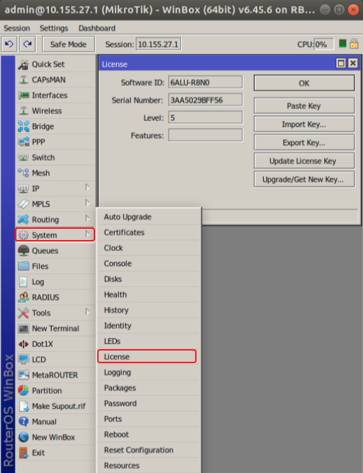
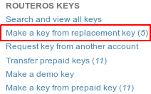
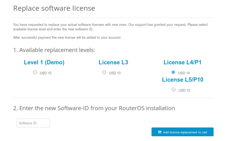
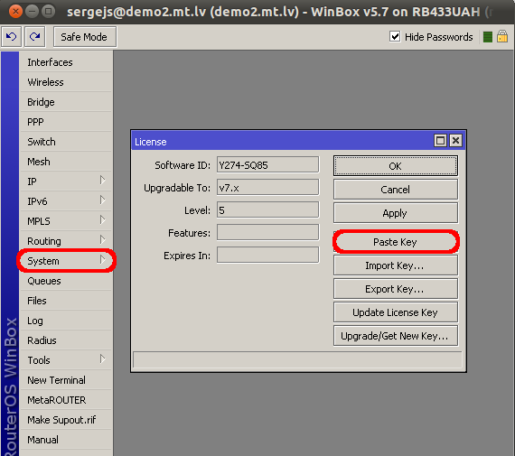
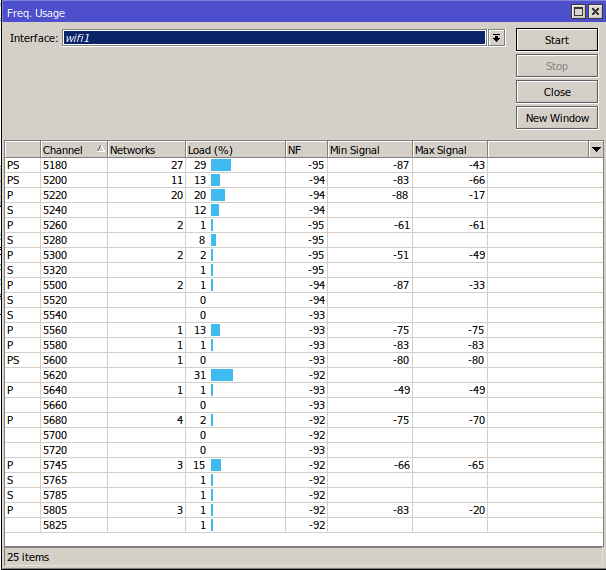
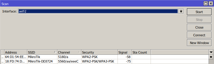
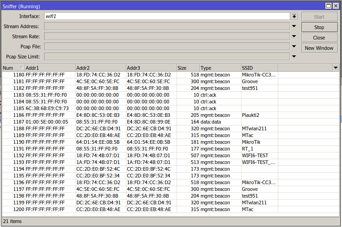


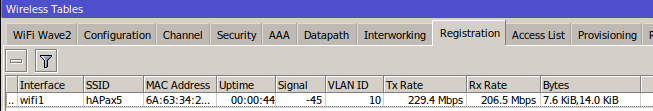
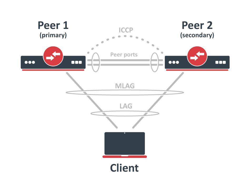
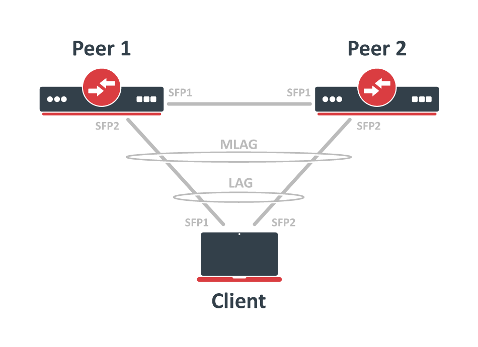
MikroTik newsletter
To follow the latest product and software news, make sure to read our newsletters in the blog section.