Documentation
This document describes RouterOS, the operating system of MikroTik devices.
While the documentation is still being migrated, many additional articles are located in our old documentation portal..
|
Confluence Syndication Feed |
|||||||||||||||||||||||||||||||||||||||||||||||||||||||||||||||||||||||||||||||||||||||||||||||||||||||||||||||||||||
|---|---|---|---|---|---|---|---|---|---|---|---|---|---|---|---|---|---|---|---|---|---|---|---|---|---|---|---|---|---|---|---|---|---|---|---|---|---|---|---|---|---|---|---|---|---|---|---|---|---|---|---|---|---|---|---|---|---|---|---|---|---|---|---|---|---|---|---|---|---|---|---|---|---|---|---|---|---|---|---|---|---|---|---|---|---|---|---|---|---|---|---|---|---|---|---|---|---|---|---|---|---|---|---|---|---|---|---|---|---|---|---|---|---|---|---|---|---|
|
ARP
Page edited by Guntis G. - "typos" SummarySub-menu: Even though IP packets are addressed using IP addresses, hardware addresses must be used to transport data from one host to another. Address Resolution Protocol is used to map OSI level 3 IP addresses to OSI level 2 MAC addresses. A router has a table of currently used ARP entries. Normally the table is built dynamically, but to increase network security, it can be partially or completely built statically by adding static entries. PropertiesThis section describes the ARP table configuration options.
The default maximum number of ARP entries depends on the installed amount of RAM. It can be adjusted with the command " ARP ModesIt is possible to set several ARP modes on the interface configuration.
DisabledIf the ARP feature is turned off on the interface, i.e., C:\> arp -s 10.5.8.254 00-aa-00-62-c6-09 EnabledThis mode is enabled by default on all interfaces. ARPs will be discovered automatically and new dynamic entries will be added to the ARP table. Proxy ARPA router with a properly configured proxy ARP feature acts as a transparent ARP proxy between different networks. This behavior can be useful, for example, if you want to assign dial-in (ppp, pppoe, pptp) clients' IP addresses from the same address space as used on the connected LAN. Proxy ARP can be enabled on each interface individually with the command Setup proxy ARP: [admin@MikroTik] /interface ethernet> set 1 arp=proxy-arp [admin@MikroTik] /interface ethernet> print Flags: X - disabled, R - running # NAME MTU MAC-ADDRESS ARP 0 R ether1 1500 00:30:4F:0B:7B:C1 enabled 1 R ether2 1500 00:30:4F:06:62:12 proxy-arp Reply OnlyIf ARP property is set to Local Proxy ArpIf the ARP property is set to With E.g. If Host A (192.168.88.2/24) queries for the MAC address of Host B (192.168.88.3/24), the router would respond with its own MAC address. In other words, if An example for RouterOS /interface bridge add arp=local-proxy-arp name=bridge1 /interface bridge port add bridge=bridge1 horizon=1 interface=ether2 add bridge=bridge1 horizon=1 interface=ether3 add bridge=bridge1 horizon=1 interface=ether4 Gratuitous ARPIt is possible to create Gratuitous ARP requests in RouterOS. To do so you must use the Traffic-Generator tool, below is an example of how to generate a Gratuitous ARP request to update the ARP table on a remote device: /tool traffic-generator inject interface=ether2 \ data="ffffffffffff4c5e0c14ef78080600010800060400014c5e0c14ef780a057a01ffffffffffff0a057a01000000000000000000000000000000000000" You must change the MAC address (4c5e0c14ef78) and the IP address (0a057a01) to your router's address. The IP address and the MAC address must be from the device that requests an ARP table update. You also need to specify through which interface (ether2) you want to send the Gratuitous ARP request. Make sure that the receiving device supports Gratuitous ARP requests. |
|||||||||||||||||||||||||||||||||||||||||||||||||||||||||||||||||||||||||||||||||||||||||||||||||||||||||||||||||||||
|
Dual SIM Application
Page edited by Guntis G. - "typos" SummaryThe first script example shows how to switch between SIM slots in case mobile roaming is detected for LtAP mini devices. This could be useful for mobile vehicle applications, where cars, buses or trains could drive abroad and should use two SIM cards (one for a home network, other for a roaming network). Since RouterOS has a roaming status in the LTE monitor (displayed only when roaming) we can use this in RouterOS scripts to change SIM cards accordingly. The second script example shows how to switch between the SIM cards in case a mobile connection is lost on the currently selected one. Note: Keep in mind that these are just examples of how to utilize dual SIM slots. For real-life production environments, proper testing should be carried out, so try to optimize them and add new features according to your needs. Initial settingsFirst, make sure you have correctly set up LTE network parameters (provided by the mobile network operator) for each SIM card. You can use the default APN profile or create two separate ones, follow this link - LTE#Quicksetupexample. This example uses the default APN profile. After that, enable data roaming for connecting to other countries data-providers with the following command. This allows us to keep track of roaming status. /interface lte set [find name=lte1] allow-roaming=yes Then, choose which SIM slots will be used for home and roaming networks. In this example, we use slot "down" for home and slot "up" for roaming network. Use the following command to switch between active slots.
/system routerboard sim set sim-slot=down Command after 6.45.1: /system routerboard modem set sim-slot=down Command in RouterOS v7 version: /interface lte settings set sim-slot=down After changing SIM slots, LTE modem will be restarted. It can take some time (depending on the modem and board around 30 seconds) to fully initialize it, so make sure you test your modem. Roaming script exampleNow create a script that will run with a scheduler. This script will go through a few key points:
Let's call this script "roamingScript", and see below the source: {
# Setup and read current values, "up" SIM slot will be used for roaming, "down" for home network
:global simSlot [/system routerboard sim get sim-slot]
:global timeoutLTE 60
:global timeoutConnect 60
# Wait for LTE to initialize for maximum "timeoutLTE" seconds
:local i 0
:local isLTEinit false
:while ($i<$timeoutLTE) do={
:foreach n in=[/interface lte find] do={:set $isLTEinit true}
:if ($isLTEinit=true) do={
:set $i $timeoutLTE
}
:set $i ($i+1)
:delay 1s
}
# Check if LTE is initialized, or try power-reset the modem
:if ($isLTEinit=true) do={
# Wait for LTE interface to connect to mobile network for maximum "timeoutConnet" seconds
:local isConnected false
:set $i 0
:while ($i<$timeoutConnect) do={
:if ([/interface lte get [find name="lte1"] running]=true) do={
:set $isConnected true
:set $i $timeoutConnect
}
:set $i ($i+1)
:delay 1s
}
# Check if LTE is connected
if ($isConnected=true) do={
:local Info [/interface lte monitor lte1 once as-value]
:local isRoaming ($Info->"roaming")
# Check which SIM slot is used
:if ($simSlot="down") do={
# If "down" (home) slot, check roaming status
:if ($isRoaming=true) do={
:log info message="Roaming detected, switching to SIM UP (Roaming)"
/system routerboard sim set sim-slot=up
}
} else={
# Else "up" (roaming) slot, check roaming status
:if (!$isRoaming=true) do={
:log info message="Not roaming, switching to SIM DOWN (Home)"
/interface lte settings set sim-slot=down
}
}
} else={
:log info message="LTE interface did not connect to network, wait for next scheduler"
}
} else={
:log info message="LTE modem did not appear, trying power-reset"
/system routerboard usb power-reset duration=5s
}
}
Failover script exampleNow create a script that will run with a scheduler. This script will go through a few key points:
Note: Keep in mind that the SIM slot will only be changed if the current one is not able to connect to the network if you need to switch back to the main SIM card you need to schedule another action that does it at a certain time. It is not possible to know if the other SIM card is in service without switching back to it. Let's call this script "failoverScript", and see below the source: Setting up schedulerLast, create your scheduler that will run the previously created script. Choose a proper scheduler interval, so two or more events do not overlap with each other. For this example above, 3 minutes will be enough. /system scheduler add interval=3m on-event=roamingScript name=Roaming /system scheduler add interval=3m on-event=failoverScript name=Failover Keep in mind that a "home" SIM card will consume some roaming data because changing SIM slots does not happen instantly. |
|||||||||||||||||||||||||||||||||||||||||||||||||||||||||||||||||||||||||||||||||||||||||||||||||||||||||||||||||||||
|
SMS
Page edited by Guntis G. - "typos" SummaryIt is possible to connect the GSM modem to the RouterOS device and use it to send and receive SMS messages. RouterOS lists such modem as a serial port that appears in the ' Sending/tool sms send ExampleSending command for ppp interface: /tool sms send usb3 "20000000" \ message="ABCDEFGHIJKLMNOPQRSTUVWXYZabcdefghijklmnopqrstuvwxyz!@#\$%^&*(){}[]\"'~" For LTE interface use LTE interface name in the port field: /tool sms send lte1 "20000000" \ message="ABCDEFGHIJKLMNOPQRSTUVWXYZabcdefghijklmnopqrstuvwxyz!@#\$%^&*(){}[]\"'~"
USSD messagesUSSD (Unstructured Supplementary Service Data) messages can be used to communicate with mobile network provider to receive additional information, enabling additional services or adding funds to prepaid cards. USSD messages can be processed by using AT commands (commands can differ or even may be blocked on some modems). 3G or GSM network modes must be activated to use this functionality, as it's not supported under LTE only mode (R11e-LTE modem auto switches to 3G mode to send out USSD message). PDU (Protocol Data Unit) message and its decrypted version are printed under LTE debug logging. ExampleCheck if LTE debug logging is active: /system logging print Flags: X - disabled, I - invalid, * - default # TOPICS ACTION PREFIX 0 * info memory 1 * error memory 2 * warning memory 3 * critical echo If there is no logging entry add it by running this command: /system logging add topics=lte,!raw /system logging print Flags: X - disabled, I - invalid, * - default # TOPICS ACTION PREFIX 0 * info memory 1 * error memory 2 * warning memory 3 * critical echo 4 lte,!raw memory To receive account status from *245# /interface lte at-chat lte1 input="AT+CUSD=1,\"*245#\",15" output: OK /log print 11:51:20 lte,async lte1: sent AT+CUSD=1,"*245#",15 11:51:20 lte,async lte1: rcvd OK 11:51:23 lte,async,event +CUSD: 0,"EBB79B1E0685E9ECF4BADE9E03", 0 11:51:23 gsm,info USSD: konta atlikums ReceivingRouterOS also supports receiving of SMS messages, can execute scripts, and even respond to the sender. Before the router can receive SMS, the relevant configuration is required in the
Basic Example configuration to be able to view received messages: /tool sms set receive-enabled=yes port=lte1
/tool/sms/print
status: running
receive-enabled: yes
port: lte1
channel: 0
secret:
allowed-number:
auto-erase: no
sim-pin:
last-ussd: Inbox/tool sms inbox If you have enabled the reader, you will see incoming messages in this submenu: Read-only properties:
Syntax:cmd SECRET script NAME [[ VAR[=VAL] ] ... ]
Other things to remember:
ExamplesWrong: :cmd script mans_skripts :cmd slepens script mans skripts :cmd slepens script mans_skripts var= :cmd slepens script mans_skripts var= a :cmd slepens script mans_skripts var=a a Right: :cmd slepens script mans_skripts :cmd slepens script "mans skripts" :cmd slepens script mans_skripts var :cmd slepens script mans_skripts var=a :cmd slepens script mans_skripts var="a a" Debugging
Implementation detailsAT+CMGS and AT+CMGF commands are used. Port is acquired for the duration of the command and cannot be used concurrently by another RouterOS component. Message sending process can take a long time, it times out after a minute and after two seconds during the initial AT command exchange. |
|||||||||||||||||||||||||||||||||||||||||||||||||||||||||||||||||||||||||||||||||||||||||||||||||||||||||||||||||||||
|
LTE
Page edited by Guntis G. - "typos"
|
| Property | Description |
|---|---|
| allow-roaming (yes | no; Default: no) | Enable data roaming for connecting to other countries' data-providers. Not all LTE modems support this feature. Some modems, that do not fully support this feature, will connect to the network but will not establish an IP data connection with allow-roaming set to no. |
| apn-profiles (string; Default: default) | Which APN profile to use for this interface |
| band (integer list; Default: "") | LTE Frequency band used in communication LTE Bands and bandwidths |
| nr-band (integer list; Default: "") | 5G NR Frequency band used in communication 5G NR Bands and bandwidths |
| comment (string; Default: "") | Descriptive name of an item |
| disabled (yes | no; Default: yes) | Whether the interface is disabled or not. By default it is disabled. |
| modem-init (string; Default: "") | Modem init string (AT command that will be executed at modem startup) |
| mtu (integer; Default: 1500) | Maximum Transmission Unit. Max packet size that the LTE interface will be able to send without packet fragmentation. |
| name (string; Default: "") | Descriptive name of the interface. |
| network-mode (3g | gsm | lte | 5g) | Select/force mode for LTE interface to operate with |
| operator (integer; Default: "") | used to lock the device to a specific operator full PLMN number is used for the lock consisting of MCC+MNC. PLMN codes |
| pin (integer; Default: "") | SIM Card's PIN code. |
APN profiles
All network-related settings are under profiles
Sub-menu: /interface lte apn
| Property | Description |
|---|---|
| add-default-route (yes | no) | Whether to add a default route to forward all traffic over the LTE interface. |
| apn (string) | Service Provider's Access Point Name |
| authentication (pap | chap | none; Default: none) | Allowed protocol to use for authentication |
| default-route-distance (integer; Default: 2) | Sets distance value applied to auto-created default route, if add-default-route is also selected. LTE route by default is with distance 2 to prefer wired routes over LTE |
| ip-type (ipv4 | ipv4-ipv6 | ipv6; Default: ) | Requested PDN type |
| ipv6-interface (; Default: ) | Interface on which to advertise IPv6 prefix |
| name (string; Default: ) | APN profile name |
| number (integer; Default: ) | APN profile number |
| passthrough-interface (; Default: ) | Interface to passthrough IP configuration (activates passthrough) |
| passthrough-mac (MAC; Default: auto) | If set to auto, then will learn MAC from the first packet |
| passthrough-subnet-selection (auto / p2p; Default: auto) | "auto" selects the smallest possible subnet to be used for the passthrough interface. "p2p" sets the passthrough interface subnet as /32 and picks gateway address from 10.177.0.0/16 range. The gateway address stays the same until the apn configuration is changed. |
| password (string; Default: ) | Password used if any of the authentication protocols are active |
| use-network-apn (yes | no; Default: yes) | Parameter is available starting from RouterOS v7 and used only for MBIM modems. If set to yes, uses network provided APN. |
| use-peer-dns (yes | no; Default: yes) | If set to yes, uses DNS received from LTE interface |
| user (integer) | Username used if any of the authentication protocols are active |
LTE settings
LTE and router-specific LTE settings. The menu is available starting from RouterOS v7.
Sub-menu: /interface lte settings
| Property | Description |
|---|---|
| mode (auto | mbim | serial; Default: auto) | Operation mode setting.
|
| firmware-path (string) | Firmware path in host OS. Modem gobi firmware |
| external-antenna (auto | both | div | main | none; Default: auto) | This setting is only available for "Chateau" routers, except for Chateau 5G versions.
|
| external-antenna-selected () | This setting is only available for "Chateau" routers, except for Chateau 5G versions. Shows the currently selected antenna if "external-antenna" is set to "auto" |
| sim-slot () | This setting is available for routers that have switchable SIM slots (LtAP, SXT). Selection options differ between products. |
Scanner
It is possible to scan LTE interfaces with /interface lte scan command. Example:
[admin@MikroTik] > /interface lte scan duration=60 number=0
Columns: OPERATOR, MCC-MNC, RSSI, RSRP, RSRQ
OPERATOR  MCC-MNC  RSSI    RSRP    RSRQ
LMT         24701  -36dBm  -63dBm  -7dB
Available properties:
| Property | Description |
|---|---|
| duration (integer) | Duration of scan in seconds |
| freeze-frame-interval (integer) | time between data printout |
| number (integer) | Interface number or name |
User Info command
It is possible to send a special "info" command to LTE interface with /interface lte info command. In RouterOS v7 this command is moved to /interface lte monitor menu.
Properties (Up to 6.40)
| Property | Description |
|---|---|
| user-command (string; Default: "") | send a command to the LTE card to extract useful information, e.g. with AT commands |
| user-command-only (yes | no; Default: ) |
User at-chat command
It is possible to send user defined "at-chat" command to the LTE interface with /interface lte at-chat command.
[admin@MikroTik] > /interface lte at-chat lte1 input="AT"
  output: OK
It is also possible to use the "wait" parameter wait=yes with the command to make "at-chat" wait for 5 seconds and return all the output instead of returning only the first received data, this is useful for some commands that return multiline output or a large block of data.
[admin@MikroTik] > interface lte at-chat lte1 input="at+qcfg=?"
  output:

[admin@MikroTik] > interface lte at-chat lte1 input="at+qcfg=?" wait=yes
  output: +QCFG: "rrc",(0-5)
          +QCFG: "hsdpacat",(6,8,10-24)
          +QCFG: "hsupacat",(5,6)
          +QCFG: "pdp/duplicatechk",(0,1)
          +QCFG: "risignaltype",("respective","physical")
          +QCFG: "lte/bandprior",(1-43),(1-43),(1-43)
          +QCFG: "volte_disable",(0,1)
          +QCFG: "diversity/config",(4,6),(1-4),(0)
          +QCFG: "div_test_mode",(0,1)
          +QCFG: "usbspeed",("20","30")
          +QCFG: "data_interface",(0,1),(0,1)
          +QCFG: "pcie/mode",(0,1)
          +QCFG: "pcie_mbim",(0,1)
          +QCFG: "sms_control",(0,1),(0,1)
          +QCFG: "call_control",(0,1),(0,1)
          +QCFG: "usb/maxpower",(0-900)
          +QCFG: "efratctl",(0,1)
          +QCFG: "netmaskset",(0,1)[,<netmask>]
          +QCFG: "mmwave",ant_chip,ant_type
          +QCFG: "gatewayset",(0,1)[,<gateway>]
          +QCFG: "clat",(0,1),(0,1),<prefix>,(0,32,40,48,56,64,96),<fqdn>,(0,1),(0,1,2,4,8),(0,1),(0,1),(0,1,2),(0,1,2)
          +QCFG: "usage/apmem"
          +QCFG: "enable_gea1"[,(0,1)]
          +QCFG: "dhcppktfltr",(0,1)
          OK
You can also use "at-chat" function in scripts and assign command output to variable.
[admin@MikroTik] > :global "lte_command" [/interface lte at-chat lte1 input="AT+CEREG?" as-value ]
[admin@MikroTik] > :put $"lte_command"
output=+CEREG: 0,1
OK
Quick setup example
Start with network settings - Add new connection parameters under LTE apn profile (provided by network provider):
/interface lte apn add name=profile1 apn=phoneprovider.net authentication=chap password=web user=web
Select the newly created profile for an LTE connection:
/interface lte set [find] apn-profiles=profile1
LTE interface should appear with the running (R) flag:
[admin@MikroTik] > /interface lte print
Flags: X - disabled, R - running
0 R name="lte1" mtu=1500 mac-address=AA:AA:AA:AA:AA:AA
If required, add NAT Masquerade for LTE Interface to get internet to the local network:
/ip firewall nat add action=masquerade chain=srcnat out-interface=lte1
After the interface is added, you can use the "info" command to see what parameters the client acquired (parameters returned depends on the LTE hardware device):
[admin@MikroTik] > interface/lte/monitor lte1
            status: connected
             model: EG18-EA
          revision: EG18EAPAR01A12M4G
  current-operator: LMT
    current-cellid: 3103242
            enb-id: 12122
         sector-id: 10
        phy-cellid: 480
        data-class: LTE
    session-uptime: 15m54s
              imei: 86981604098XXXX
              imsi: 24701060267XXXX
              uicc: 8937101122102057XXXX
      primary-band: B3@20Mhz earfcn: 1300 phy-cellid: 480
     dl-modulation: qpsk
               cqi: 7
                ri: 2
               mcs: 1
              rssi: -68dBm
              rsrp: -97dBm
              rsrq: -9dB
              sinr: 6dB
Passthrough Example
Some LTE interfaces support the LTE Passthrough feature where the IP configuration is applied directly to the client device. In this case, modem firmware is responsible for the IP configuration, and the router is used only to configure modem settings - APN, Network Technologies, and IP-Type. In this configuration, the router will not get IP configuration from the modem. The LTE Passthrough modem can pass both IPv4 and IPv6 addresses if that is supported by the modem. Some modems support multiple APNs where you can pass the traffic from each APN to a specific router interface.
Passthrough will only work for one host. The router will automatically detect the MAC address of the first received packet and use it for the Passthrough. If there are multiple hosts on the network it is possible to lock the Passthrough to a specific MAC. On the host on the network where the Passthrough is providing the IP a DHCP-Client should be enabled on that interface too. Note, that it will not be possible to connect to the LTE router via a public lte IP address or from the host which is used by the passthrough. It is suggested to create an additional connection from the LTE router to the host for configuration purposes. For example vlan interface between the LTE router and host.
To enable the Passthrough a new entry is required or the default entry should be changed in the '/interface lte apn' menu
Examples.
To configure the Passthrough on ether1:
[admin@MikroTik] > /interface lte apn add apn=apn1 passthrough-interface=ether1
[admin@MikroTik] > /interface lte set lte1 apn-profiles=apn1
To configure the Passthrough on ether1 host 00:0C:42:03:06:AB:
[admin@MikroTik] > /interface lte apn add apn=apn1 passthrough-interface=ether1 passthrough-mac=00:0C:42:03:06:AB
[admin@MikroTik] > /interface lte set lte1 apn-profiles=apn1
To configure multiple APNs on ether1 and ether2:
[admin@MikroTik] > /interface lte apn add apn=apn1 passthrough-interface=ether1
[admin@MikroTik] > /interface lte apn add apn=apn2 passthrough-interface=ether2
[admin@MikroTik] > /interface lte set lte1 apn-profiles=apn1,apn2
To configure multiple APNs with the same APN for different interfaces:
[admin@MikroTik] > /interface lte apn add name=interface1 apn=apn1
[admin@MikroTik] > /interface lte apn add name=interface2 apn=apn1 passthrough-interface=ether1
[admin@MikroTik] > /interface lte set lte1 apn-profiles=interface1
[admin@MikroTik] > /interface lte set lte2 apn-profiles=interface2
Dual SIM
Boards with switchable SIM slots
| RouterBoard | Modem slot | SIM slots | Switchable |
|---|---|---|---|
| LtAP | lower | 2 | 3 | Y |
| upper | 1 | N | |
| LtAP mini | up | down | Y | |
| SXT R | a | b | Y |
SIM slots switching commands
- RouterOS v7
/interface lte settings set sim-slot=down
- RouterOS v6 after 6.45.1
/system routerboard modem set sim-slot=down
- RouterOS v6 pre 6.45.1:
/system routerboard sim set sim-slot=down
For more reference please see the board block diagram, Quick Guide, and User manual.
Usage Example
Follow this link - Dual SIM Application, to see examples of how to change SIM slot based on roaming status and in case the interface status is down, with the help of RouterOS scripts and scheduler.
Tips and Tricks
This paragraph contains information for additional features and usage cases.
Find device location using Cell information
On devices using the R11e-LTE International version card (wAP LTE kit) some extra information is provided under info command.
   current-operator: 24701
                lac: 40
current-cellid: 2514442| Property | Description |
|---|---|
| current-operator (integer; Default: ) | Contains MCC and MNC. For example: current-operator: 24701 breaks to: MCC=247 MNC=01 |
| lac (integer; Default: ) | location area code (LAC) |
| current-cellid (integer; Default: ) | Station identification number |
Values can be used to find location in databases: Cell Id Finder
Using Cell lock
It is possible to lock R11e-LTE, R11e-LTE6 and R11e-4G modems and equipped devices to the exact LTE tower. LTE info command provides currently used cellular tower information:
         phy-cellid: 384
earfcn: 1300 (band 3, bandwidth 20Mhz)| Property | Description |
|---|---|
| phy-cellid (integer; Default: ) | Physical Cell Identification (PCI) of currently used cell tower. |
| earfcn (integer; Default: ) | Absolute Radio Frequency Channel Number |
Exact tower location as well as available bands and other information can be acquired from mobile carrier or by using online services:
By using those acquired variables it's possible to send the AT command to modem for locking to tower in the current format:
for R11e-LTE and R11e-LTE6
AT*Cell=<mode>,<NetworkMode>,<band>,<EARFCN>,<PCI>

where

<mode> :
0 – Cell/Frequency disabled
1 – Frequency lock enabled
2 – Cell lock enabled

<NetworkMode>
0 – GSM
1 – UMTS_TD
2 – UMTS_WB
3 – LTE

<band>
Not in use, leave this blank

<EARFCN>
earfcn from lte info

<PCI>
phy-cellid from lte info
To lock modem at previously used tower at-chat can be used:
/interface lte at-chat lte1 input="AT*Cell=2,3,,1300,384"
For R11e-LTE all set on locks are lost after reboot or modem reset. Cell data can be also gathered from "cell-monitor".
For R11e-LTE6 cell lock works only for the primary band, this can be useful if you have multiple channels on the same band and you want to lock it to a specific earfcn. Note, that cell lock is not band-specific and for ca-band it can also use other frequency bands, unless you use band lock.
Use cell lock to set the primary band to the 1300 earfcn and use the second channel for the ca-band:
/interface lte at-chat lte1 input="AT*Cell=2,3,,1300,138"
Now it uses the earfcn: 1300 for the primary channel:
         primary-band: B3@20Mhz earfcn: 1300 phy-cellid: 138
              ca-band: B3@5Mhz earfcn: 1417 phy-cellid: 138
You can also set it the other way around:
/interface lte at-chat lte1 input="AT*Cell=2,3,,1417,138"
Now it uses the earfcn: 1417 for the primary channel:
         primary-band: B3@5Mhz earfcn: 1417 phy-cellid: 138
              ca-band: B3@20Mhz earfcn: 1300 phy-cellid: 138
For R11e-LTE6 modem cell lock information will not be lost after reboot or modem reset. To remove cell lock use at-chat command:
/interface lte at-chat lte1 input="AT*Cell=0"
for R11e-4G
AT%CLCMD=<mode>,<mode2>,<EARFCN>,<PCI>,<PLMN>
AT%CLCMD=1,1,3250,244,\"24705\"

where

<mode> :
0 – Cell/Frequency disabled
1 – Cell lock enabled

<mode2> :
0 - Save lock for first scan
1 - Always use lock
(after each reset modem will clear out previous settings no matter what is used here)

<EARFCN>
earfcn from lte info

<PCI>
phy-cellid from lte info

<PLMN>
Mobile operator code
All PLMN codes available here this variable can be also left blank
To lock the modem to the cell - modem needs to be in non operating state, the easiest way for R11e-4G modem is to add CellLock line to "modem-init" string:
/interface lte set lte1 modem-init="AT%CLCMD=1,1,3250,244,\"24705\""
Multiple cells can also be added by providing a list instead of one tower information in the following format:
AT%CLCMD=<mode>,<mode2>,<EARFCN_1>,<PCI_1>,<PLMN_1>,<EARFCN_2>,<PCI_2>,<PLMN_2>
For example to lock to two different PCIs within the same band and operator:
/interface lte set lte1 modem-init="AT%CLCMD=1,1,6300,384,\"24701\",6300,385,\"24701\""
for Chateau LTE12, Chateau 5G, LHG LTE18 and ATL LTE18
AT+QNWLOCK="common/4g",<num of cells>,[[<freq>,<pci>],...]
AT+QNWLOCK=\"common/4g\",1,6300,384

where

<num of cells>
number of cells to cell lock

<freq>
earfcn from lte info

<pci>
phy-cellid from lte info
Single-cell lock example:
/interface lte at-chat lte1 input="AT+QNWLOCK=\"common/4g\",1,3050,448"
Query current configuration:
/interface lte at-chat lte1 input="AT+QNWLOCK=\"common/4g\""
Multiple cells can also be added to the cell lock. For example to lock to two different cells:
/interface lte at-chat lte1 input="AT+QNWLOCK=\"common/4g\",2,3050,448,1574,474"
To remove the cell lock use this at-chat command:
/interface lte at-chat lte1 input="at+qnwlock=\"common/4g\",0"
for Chateau LTE6
AT+GTCELLLOCK=<mode>[,<rat>,<type>,<earfcn>[,<PCI>]]

where

< mode >: integer type; 0 Disable this function 1 Enable this function 2 Add new cell to be locked

<rat>: integer type; 0 LTE 1 WCDMA

<type>: integer type; 0 Lock PCI 1 Lock frequency

<earfcn>: integer type; the range is 0-65535.

<PCI>: integer type; If second parameter value is 0, the range is 0-503 for LTE If second parameter value is 1, the rang is 0-512 for WCDMA
Example:
/interface lte at-chat lte1 input="AT+GTCELLLOCK=1,0,0,6175,176"
Cell Monitor
Cell monitor allows to scan available nearby mobile network cells:
[admin@MikroTik] > /interface lte cell-monitor lte1
PHY-CELLID BAND         PSC EARFCN                 RSRP          RSRQ          RSSI         SINR
        49 B20              6300                -110dBm       -19.5dB
       272 B20              6300                -116dBm       -19.5dB
       374 B20              6300                -108dBm         -16dB
       384 B1               150                 -105dBm       -13.5dB
       384 B3               1300                -106dBm         -12dB
       384 B7               2850                -107dBm       -11.5dB
       432 B7               2850                -119dBm       -19.5dB
Gathered data can be used for more precise location detection or for Cell lock.
Troubleshooting
Enable LTE logging:
[admin@MikroTik] > /system logging add topics=lte
Check for errors in log:
[admin@MikroTik] > /log print

11:08:59 lte,async lte1: sent AT+CPIN?
11:08:59 lte,async lte1: rcvd +CME ERROR: 10
search for CME error description online,
in this case: CME error 10 - SIM not inserted
Locking band on Huawei and other modems
To lock band for Huawei modems /interface lte set lte1 band="" option can't be used.
It is possible to use AT commands to lock to the desired band manually.
To check all supported bands run the at-chat command:
[admin@MikroTik] /interface lte at-chat lte1 input="AT^SYSCFGEX=\?"

output: ^SYSCFGEX: ("00","03","02","01","99"),((2000004e80380,"GSM850/GSM900/GSM1800/GSM1900/WCDMA BCI/WCDMA BCII/WCDMA BCV/WCDMA BCVIII"),
(3fffffff,"All Bands")),(0-2),(0-4),((800d7,"LTE BC1/LTE BC2/LTE
BC3/LTE BC5/LTE BC7/LTE BC8/LTE BC20"),(7fffffffffffffff,"All Bands"))
OK
Example to lock to LTE band 7:
[admin@MikroTik] /interface lte set lte1 modem-init="AT^SYSCFGEX=\"03\",3FFFFFFF,2,4,40,,"
Change last part 40 to desired band specified hexadecimal value where:
4 LTE BC3
40 LTE BC7
80000 LTE BC20
7FFFFFFFFFFFFFFF  All bands
etc
All band HEX values and AT commands can be found in Huawei AT Command Interface Specification guide
Check if the band is locked:
[admin@MikroTik] /interface lte at-chat lte1 input="AT^SYSCFGEX\?"

output: ^SYSCFGEX: "03",3FFFFFFF,0,2,40
OK
For more information check modem manufacturers AT command reference manuals.
mPCIe modems with RB9xx series devices
In case your modem is not being recognized after a soft reboot, then you might need to add a delay before the USB port is initialized. This can be done using the following command:
/system routerboard settings set init-delay=5s
Boards with USB-A port and mPCIe
Some devices such as specific RB9xx's and the RBLtAP-2HnD share the same USB lines between a single mPCIe slot and a USB-A port. If auto switch is not taking place and a modem is not getting detected, you might need to switch manually to either use the USB-A or mini-PCIe:
/system routerboard usb set type=mini-PCIe
Modem firmware upgrade
It is possible to upgrade modems firmware. The firmware upgrade is also possible for the Chateau series products starting from the 7.1beta1 version.
Firmware update is available only as FOTA Firmware Over The Air - firmware upgrade can only be done through a working mobile connection for:
- )R11e-LTE
- )R11e-LTE-US
Firmware update available as FOTA and as well as upgrade from file for:
- )R11e-4G
- )R11e-LTE6
Firmware update available as FOTA with access to the internet over any interface:
- )EG12-EA (Chateau LTE12)
- )RG502Q-EA (Chateau 5G)
- )EG18-EA (LHG LTE18)
Firmware updates usually include stability improvements or small bug fixes that can't be included in RouterOS.
Check the currently used firmware version by running:
[admin@MikroTik] > /interface lte info lte1 once

-----
revision: "MikroTik_CP_2.160.000_v008"
-----
Check if new firmware is available:
[admin@MikroTik] > /interface lte firmware-upgrade lte1
  installed: MikroTik_CP_2.160.000_v008
     latest: MikroTik_CP_2.160.000_v010
Upgrade firmware:
[admin@MikroTik] > /interface lte firmware-upgrade lte1 upgrade=yes
  status: downloading via LTE connection (>2min)
After a successful upgrade issue USB power-reset, reboot device or run AT+reset command, to update the modem version readout under info command:
[admin@MikroTik] > /interface lte at-chat lte1 input="AT+reset"
if modem has issues connecting to cells after update, or there are any other unrelated issues - wipe old configuration with:
/interface lte at-chat lte1 input="AT+RSTSET"
Avoiding tethering speed throttling
Some operators (TMobile, YOTA etc.) allow unlimited data only for the device the SIM card is used on, all other data coming from mobile hotspots or tethering is highly limited by volume or by throughput speed. Some sources have found out that this limitation is done by monitoring TTL (Time To Live) values from packets to determine if limitations need to be applied (TTL is decreased by 1 for each "hop" made). RouterOS allows changing the TTL parameter for packets going from the router to allow hiding sub networks. Keep in mind that this may conflict with fair use policy.
IPv4 mangle rule:
/ip firewall mangle
add action=change-ttl chain=postrouting new-ttl=set:65 out-interface=lte1 passthrough=yes
IPv6 mangle rule:
/ipv6 firewall mangle
add action=change-hop-limit chain=postrouting new-hop-limit=set:65 passthrough=yes
More information: YOTA, TMobile
Unlocking SIM card after multiple wrong PIN code attempts
After locking the SIM card, unlock can be done through "at-chat"
Check current PIN code status:
/interface lte at-chat lte1 input="at+cpin\?"
If card is locked - unlock it by providing:
/interface lte at-chat lte1 input="AT+CPIN=\"PUK_code\",\"NEW_PIN\""
Replace PUK_code and NEW_PIN with matching values.
The command for sim slot selection changes in v6.45.1 and again in v7. Some device models like SXT, have SIM slots named "a" and "b" instead of "up" and down"
Page edited by Guntis G. - "typos"
Introduction
Many RouterOS devices have GPS support. It allows RouterOS to determine the precise location of its GPS receiver. GPS coordinates will indicate the latitude and the longitude values (among other parameters) of the current position.
Let's say, you have LTAP (or any other RouterOS device with GPS support) and you wish to track its location. You want the router to send this data to a server, where the data will be stored and integrated into a map, as it is more convenient to monitor. In this guide, we will showcase how you can do that. This scenario will utilize MQTT protocol communication with a platform called ThingsBoard.
ThingsBoard has a cloud solution and different local installation options (on different OS).
Since we've added a container feature, it became possible to also run the platform within the RouterOS. Meaning, you can build this scenario, solely on RouterOS units → devices with GPS support that you wish to track (for example, cars equipped with LTAPs → RouterOS devices that act as MQTT publishers), and a ThingsBoard server run within a more powerful RouterOS device (like a CHR machine → RouterOS device that acts as an MQTT broker).
If you want to choose this route (container route), make sure to pick the devices that you plan on using as a "server" carefully, because this implementation can be heavy on RAM usage (it is suggested to have a device that has at least 2 GB RAM or 1 GB RAM with minimal load and is either ARM64 or AMD64 architecture).
Configuration
In this guide, we will demonstrate how to configure a GPS receiver (MQTT publisher) and how to set up ThingsBoard.
In case you want to use the container feature to run the ThingsBoard instance (MQTT broker), check the guide over here. General guidelines on ThingsBoard and MQTT configuration can be found in the guide over here. Make sure to explore both guides as they will have additional useful information.
Before proceeding, make sure that the ThingsBoard is up and running and that you can access its WEB management portal. Confirm that the MQTT port is open and/or port-forwarded properly.
Package requirement: gps, iot
ThingsBoard preparation
This example will showcase access-token and one-way SSL communication via access-token scenarios for simplicity reasons, but you can use other available options as well.
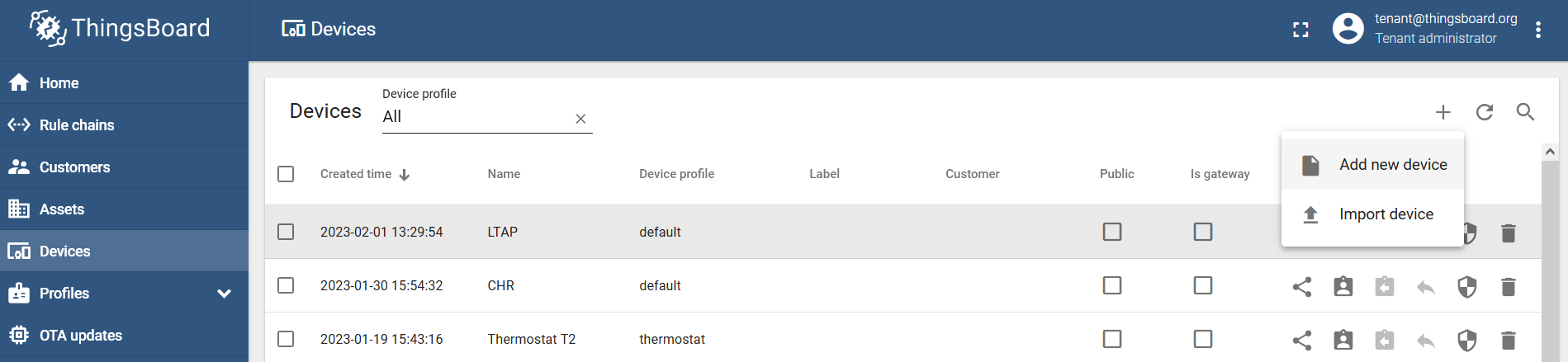
Navigate to the "Devices" menu and add a new device via the "Add new device" button → name it and create it (for example, LTAP):
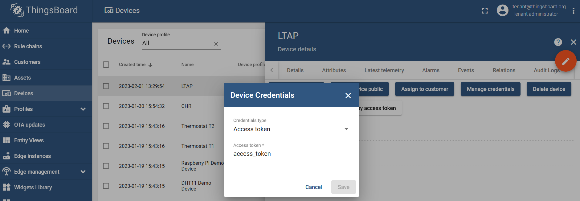
Click on the device you've just added, go to the "Details" section, and generate an access token under the "Manage credentials/Device Credentials" setting:
MQTT broker configuration
In case it is a local test or the broker is available through the VPN, you can use non-SSL MQTT:
/iot/mqtt/brokers/add name=tb address=x.x.x.x port=1883 username=access_token
Where:
nameis the name that you wish to give to the broker and this name will be used later in the script;addressis the IP address of the broker;portis the TCP port that the broker is listening for → for non-SSL it is typically TCP 1883;usernameis dictated by the MQTT broker and, in our case, it is an "access token" that was generated in the ThingsBoard management portal.
In case it is public access (when you want to access the broker via its public IP address), we advise you to use SSL MQTT:
/iot/mqtt/brokers/add name=tb address=x.x.x.x port=8883 username=access_token ssl=yes
Where:
nameis the name that you wish to give to the broker and this name will be used later in the script;addressis the IP address of the broker;portis the TCP port that the broker is listening for → for SSL it is typically TCP 8883;usernameis dictated by the MQTT broker, and, in our case, it is an "access token" that was generated in the ThingsBoard management portal;sslenables SSL MQTT communication.
MQTT publish
You can test MQTT publish with a static message by using the command:
/iot/mqtt/publish broker="tb" topic="v1/devices/me/telemetry" message="{\"test\":\"123\"}" To post GPS coordinates, import the script shown below:
/system/script/add dont-require-permissions=no name=mqttgps owner=admin policy="ftp,re\
    boot,read,write,policy,test,password,sniff,sensitive,romon" \
    source="    ###Configuration###\r\
    \n    #Enter pre-configured broker's name within \"\":\r\
    \n    :local broker \"tb\"\r\
    \n    #Enter the topic name within \"\", per the broker's config\
    uration:\r\
    \n    :local topic \"v1/devices/me/telemetry\"\r\
    \n\r\
    \n    ###Variables####\r\
    \n    :global lat\r\
    \n    :global lon\r\
    \n    :global alt1\r\
    \n    :global alt2\r\
    \n\r\
    \n    ###GPS####\r\
    \n    :put (\"[*] Capturing GPS coordinates...\")\r\
    \n    /system gps monitor once do={\r\
    \n    :set \$lat \$(\"latitude\");\r\
    \n    :set \$lon \$(\"longitude\");\r\
    \n    :set \$alt1 \$(\"altitude\")}\r\
    \n    ###remove \"meters\" from the value because JSON format wi\
    ll not understand it###\r\
    \n    :set \$alt2 [:pick \$alt1 0 [find \$alt1 \" m\"]]\r\
    \n\r\
    \n    :local message \\\r\
    \n    \"{\\\"latitude\\\":\$lat,\\\r\
    \n    \\\"longitude\\\":\$lon,\\\r\
    \n    \\\"altitude\\\":\$alt2}\"\r\
    \n\r\
    \n    ###MQTT###\r\
    \n    :if (\$lat != \"none\") do={\\\r\
    \n    :put (\"[*] Sending message to MQTT broker...\");\r\
    \n    /iot mqtt publish broker=\$broker topic=\$topic message=\$\
    message} else={:put (\"[*] Lattitude=none, not posting anything!\
    \");:log info \"Latitude=none, not posting anything!\"}"
In short, the script captures GPS information, specifically the latitude, longitude, and altitude values. Then it structures a JSON message out of them. In case, at the moment when the script is initiated, the latitude value equals anything other than "none" (equals any actual value-number) → it sends the JSON message via MQTT to the broker named "tb". In case, the GPS data can not be captured → "latitude" is recognized as "none" → the script just logs that nothing could be captured and does nothing else.
This is a very basic example. Feel free to alter the script and add your own "if" (maybe an email notification if there is no GPS signal) and additional parameters (any other RouterOS captured value, like, maybe, its firmware version) per your requirements.
Run the script with the command:
/system/script/run mqttgps
[*] Capturing GPS coordinates...
        date-and-time: feb/01/2023 10:39:37
             latitude: 56.969862
            longitude: 24.162425
             altitude: 31.799999 m
                speed: 1.000080 km/h
  destination-bearing: none
         true-bearing: 153.089996 deg. True
     magnetic-bearing: 0.000000 deg. Mag
                valid: yes
           satellites: 6
          fix-quality: 1
  horizontal-dilution: 1.42
             data-age: 0s
[*] Sending message to MQTT broker...
To automate the process, add a scheduler (to run the script, for example, every 30 seconds):
/system/scheduler/add name=mqttgpsscheduler interval=30s on-event="/system/script/run mqttgps"
Result verification
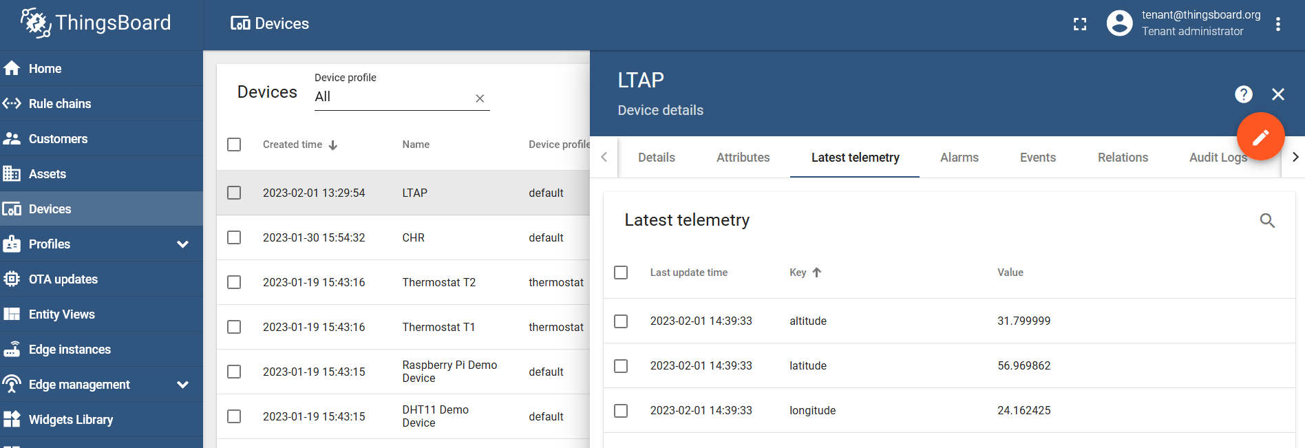
Go the the "Latest telemetry" section under your created device and confirm that the data was posted:
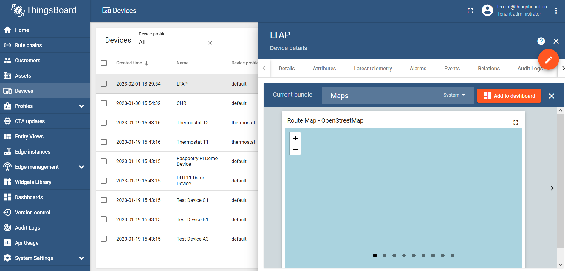
Data visualization using maps
ThingsBoard allows you to use Widgets to create visually appealing dashboards. In our case, we want to track our LTAP GPS coordinates, so we will need a map widget.
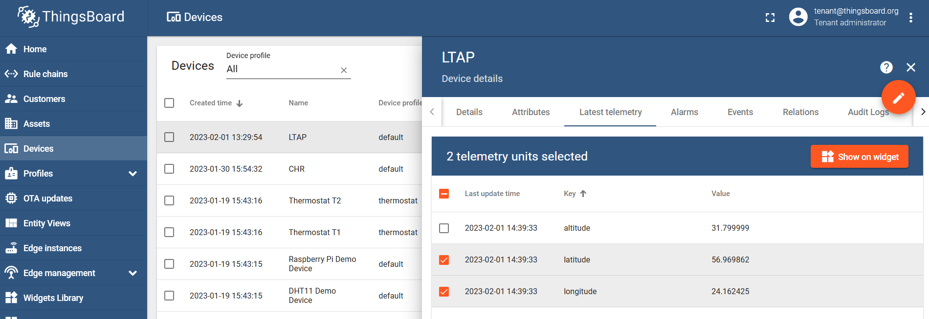
Select the latitude and longitude values and click on the "Show on widget" button:
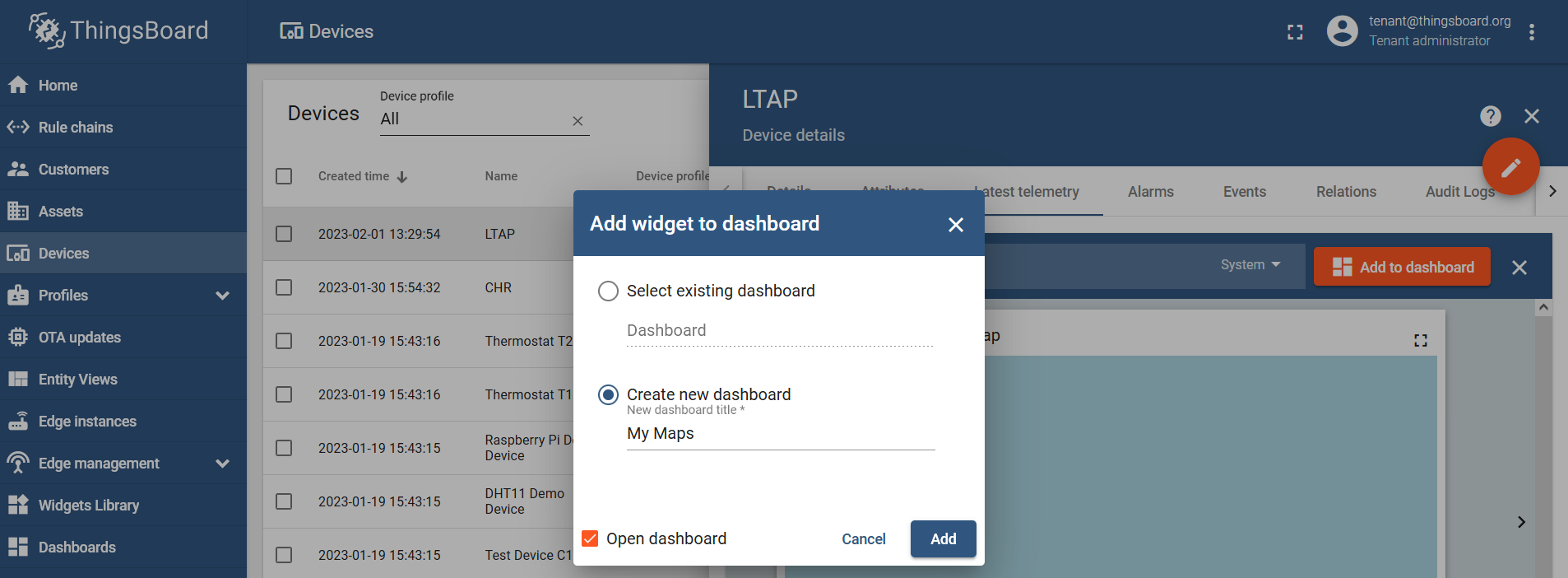
Find the "Maps" bundle and click on the "Add to dashboard":
Select an existing dashboard or create a new one and name it however you like:
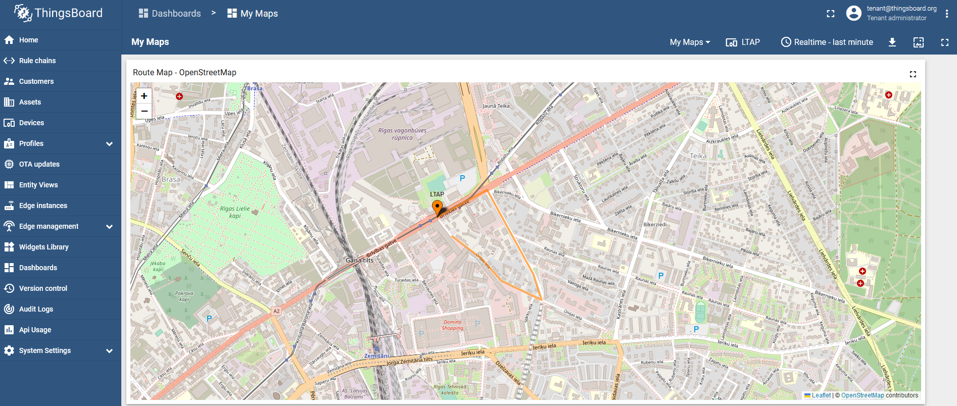
Run the script via the scheduler or manually and check the result:
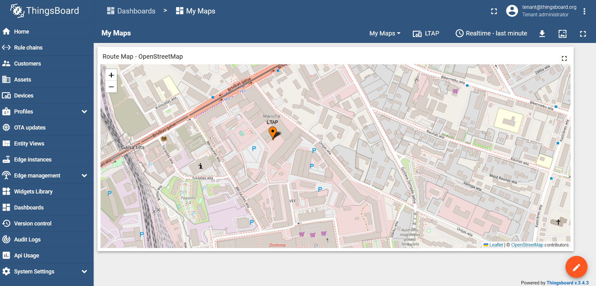
Now, we can install it on a moving target and track its location:
Page edited by Guntis G. - "typos"
The following article explains how to create a simple vehicle tracking system using the RouterOS GPS function and scripting.
Method
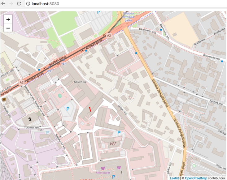
This approach uses HTTP POST capability of RouterOS Fetch tool. It allows you to POST any kind of data to a webserver, right from the RouterOS command line. Of course, you can use scripting, to fill the POST data with variables. The posted data will be written to an SQLITE3 database (file is created, if it doesn't exist) and then, read from the database and fed into a Leaflet.js PolyLine array. This is a proof of concept example, there is no authentication, security, or error handling.
Requirements
- Web server of your choice
- PHP
- SQLite3 module for PHP
- RouterOS device with a working GPS module
- RouterOS
- Set GPS format in RouterOS to dd
RouterOS script
You can run this script in the Scheduler tool, with an interval of 1s, to have your coordinates sent every 1 second.
{
:global lat
:global lon
/system gps monitor once do={
:set $lat $("latitude")
:set $lon $("longitude")
}
tool fetch mode=http url="http://YOURSERVER.com/index.php" port=80 http-method=post http-data=("{\"lat\":\"" . $lat . "\",\"lon\":\"" . $lon . "\"}") http-header-field="Content-Type: application/json"
:put ("{\"lat\":\"" . $lat . "\",\"lon\":\"" . $lon . "\"}")
}
index.php file
Create an empty directory called sqlite_db next to the index.php file. Make sure that directory and files are writable by the group with chmod -R a+w sqlite_db/
<?php
$loc = dirname(__FILE__).'/sqlite_db/coord.db';
$db = new SQLite3($loc,SQLITE3_OPEN_READWRITE | SQLITE3_OPEN_CREATE);
$raw = file_get_contents('php://input');
$raw = preg_replace('/\\x00/','',$raw);
$data = json_decode($raw);

if (!empty($data) && is_object($data) && property_exists($data,'lat') && property_exists($data,'lon')){
    if(file_exists($loc)) echo 'exists!'.chr(0xa);
    $src = 'SELECT name FROM sqlite_master WHERE type=\'table\' AND name=\'coordinates\'';
    $res = $db->querySingle($src);
    if (count($res)==0){
            $db->exec('CREATE TABLE coordinates (latitude TEXT, longitude TEXT, time TIMESTAMP DEFAULT CURRENT_TIMESTAMP, added TIMESTAMP DEFAULT CURRENT_TIMESTAMP ) ');
    }

$regex = '/^(|\-)([0-9]{2,3}\.[0-9]{0,8})$/';

if (preg_match($regex,$data->lat) && preg_match($regex,$data->lon) )
	{
		$lat = $data->lat;
		$lon = $data->lon;
	}
	$ins = 'INSERT INTO coordinates (latitude,longitude) VALUES (\''.SQLite3::escapeString($lat).'\',\''.SQLite3::escapeString($lon).'\')';
	$db->exec($ins);
	die();
}
?>

<!DOCTYPE html>
<html>
<head>
  <link rel="stylesheet" href="https://unpkg.com/leaflet@1.3.1/dist/leaflet.css" integrity="sha512-Rksm5RenBEKSKFjgI3a41vrjkw4EVPlJ3+OiI65vTjIdo9brlAacEuKOiQ5OFh7cOI1bkDwLqdLw3Zg0cRJAAQ==" crossorigin=""/>
  <script src="https://unpkg.com/leaflet@1.3.1/dist/leaflet.js" integrity="sha512-/Nsx9X4HebavoBvEBuyp3I7od5tA0UzAxs+j83KgC8PU0kgB4XiK4Lfe4y4cgBtaRJQEIFCW+oC506aPT2L1zw==" crossorigin=""></script>
</head>
<body>
<div id="map" style="width: 800px; height: 600px;"></div>
<script>
var map = L.map('map').setView([0,0], 4);
L.tileLayer('http://{s}.tile.osm.org/{z}/{x}/{y}.png', {attribution: '<a href="http://osm.org/copyright">OSM</a>'}).addTo(map);

<?php
    if($result = $db->query('SELECT latitude,longitude FROM coordinates')){
    echo ' var latlngs = [ ';
    while($obj = $result->fetchArray()){
    	if (!is_array($obj) || !isset($obj['latitude']) || !isset($obj['longitude']) || empty($obj['latitude']) || empty($obj['longitude'])) continue;
    	echo '["'. $obj['latitude'].'","'.$obj['longitude'].'"],';
    }
    echo ']; ';
    } else
     echo('//'.$db->lastErrorMsg().chr(0xa));
	 echo($data);
?>
var polyline = L.polyline(latlngs, {color: 'red'}).addTo(map);
map.fitBounds(polyline.getBounds());
</script>
</body>
</html>
Result
Page edited by Guntis G. - "typos"
Summary
Package requirement: gps
Sub-menu: /system gps
Standards: GPS, NMEA 0183, Simple Text Output Protocol
Global Positioning System (GPS) is used for determining the precise location of a GPS receiver.
Configuration Properties
| Property | Description |
|---|---|
| channel (integer [0..4294967295]; Default: 0) | Port channel used by the device |
| coordinate-format (dd | dms | ddmm; Default: no) | Which coordinate format to use, "Decimal Degrees", "Degrees Minutes Seconds" or "NMEA format DDDMM.MM[MM]" |
| enabled (yes | no; Default: no) | Whether GPS is enabled |
| gps-antenna-select (external | internal; Default: internal) | Depending on the model. Internal antenna can be selected, if the device has one installed. |
| init-channel (integer [0..4294967295]; Default: ) | Channel for init-string execution |
| init-string (string; Default: ) | AT init string for GPS initialization |
| port (string; Default: ) | Name of the USB/Serial port where the GPS receiver is connected |
| set-system-time (yes | no; Default: no) | Whether to set the router's date and time to one received from GPS. |
Monitoring Status
Command: /system gps monitor
This command is used for monitoring the data received from a GPS receiver.
Parameters:
Starting with the 7.1rc3 firmware release, a new parameter was added, called "data-age" (measured in seconds). This parameter displays the time that has passed since the device received the last NMEA message.
| Property | Description |
|---|---|
| date-and-time (date) | Date and time received from GPS |
| latitude (none | string) | Latitude in DM (Degrees Minute decimal) format |
| longitude (none | string) | Longitude in DM (Degrees Minute decimal) format |
| altitude (none | string) | Altitude based on GPS data |
| speed (none | string) | The current moving speed of the GPS unit |
| destination-bearing (none | string) | The direction toward which a GPS is moving |
| true-bearing (none | string) | The direction toward which a GPS is moving |
| magnetic-bearing (none | string) | The direction toward which a GPS is moving |
| valid (yes | no) | |
| satellites (integer) | Number of satellites seen by the device. |
| fix-quality (integer) | Quality of the signal |
| horizontal-dilution (integer) | Horizontal dilution of precision (HDOP); |
| data-age (integer) | The time that has passed since the device received the last NMEA message |
Basic examples
Check port usage, as only one instance can use the serial port simultaneously:
[admin@MikroTik] /port print
Flags: I - inactive
 #   DEVICE NAME                     CHANNELS USED-BY                   BAUD-RATE
 0          serial0                         1 Serial Console            auto
In case there is one port and it is used by the console, release it from the console menu:
[admin@MikroTik] > /system console print
Flags: X - disabled, U - used, F - free
 #   PORT                                                                       TERM
 0 U serial0                                                                    vt102

[admin@MikroTik] > /system console disable 0
Adjust port settings specifically for your device (leave "auto" for LtAP mini):
[admin@MikroTik] /port> set 0 baud-rate=4800 parity=odd
[admin@MikroTik] /port> print detail
Flags: I - inactive
 0   name="usb1" used-by="" channels=1 baud-rate=4800 data-bits=8 parity=odd stop-bits=1 flow-control=none
Enable GPS:
[admin@MikroTik] /system gps> set enable=yes port=usb1
[admin@MikroTik] /system gps> print
          enabled: yes
             port: usb1
          channel: 0
     init-channel: 0
      init-string:
  set-system-time: no
Monitor status:
[admin@MikroTik] /system gps> monitor
        date-and-time: sep/07/2021 08:26:26
             latitude: 56.969689
            longitude: 24.162471
             altitude: 25.799999m
                speed: 0.759320 km/h
  destination-bearing: none
         true-bearing: 185.500000 deg. True
     magnetic-bearing: 0.000000 deg. Mag
                valid: yes
           satellites: 6
          fix-quality: 1
  horizontal-dilution: 1.3
Port and GPS settings for LtAP
/port set serial1 baud-rate=115200
/system gps set port=serial1 channel=0 enabled=yes
We have also created an in-depth article about live GPS tracking, using scripting and a web server: GPS-tracking.
Troubleshooting
Note that sometimes to make the GPS module recognized in RouterOS you need to change the baud-rate setting in the '/port' menu.
LtAP mini has a low-gain GPS antenna built-in and for a better experience, we suggest using an additional external antenna.
Switch between internal and external antennas under the GPS menu:
[admin@MikroTik] > /system gps set gps-antenna-select=external
On some modems with GPS support, you need to send multiple init commands for continuous GPS monitoring, for example, for Huawei cards you need to send "AT^WPDST=1,AT^WPDGP" init string to get continuous monitoring.
Page edited by Guntis G. - "typos"
Introduction
Connection Rate is a firewall matcher that allows capturing traffic based on the present speed of the connection.
Theory
Each entry in the connection tracking table represents bidirectional communication. Every time a packet gets associated with a particular entry, the packet size value (including the IP header) is added to the "connection-bytes" value for this entry. (in other words "connection-bytes" includes both - upload and download).
Connection Rate calculates the speed of connection based on the change of "connection-bytes". The connection rate is recalculated every second and does not have any averages.
Both options "connection-bytes" and "connection-rate" work only with TCP and UDP traffic. (you need to specify a protocol to activate these options). In the "connection-rate" you can specify a range of speed that you like to capture:
ConnectionRate ::= [!]From-To
  From,To ::= 0..4294967295    (integer number)
Rule Example
These rules will capture TCP/UDP traffic that was going through the router when the connection speed was below 100kbps:
/ip firewall filter
add action=accept chain=forward connection-rate=0-100k protocol=tcp
add action=accept chain=forward connection-rate=0-100k protocol=udp
Application Example - Traffic Prioritization
Connection-rate can be used in various ways, that still need to be realized, but the most common setup will be to detect and set lower priorities to the "heavy connections" (connections that maintain a fast rate for long periods (such as P2P, HTTP, FTP downloads). By doing this you can prioritize all other traffic that usually includes VoIP and HTTP browsing and online gaming.
The method described in this example can be used together with other ways to detect and prioritize traffic. As the connection-rate option does not have any averages we need to determine what will be the margin that identifies "heavy connections". If we assume that a normal HTTP browsing connection is less than 500kB (4Mb) long and VoIP requires no more than 200kbps speed, then every connection that after the first 500kB still has more than 200kbps speed can be assumed as "heavy".
(You might have different "connection-bytes" for HTTP browsing and different "connection-rate" for VoIP in your network - so, please, do your own research before applying this example)
For this example, let's assume that we have a 6Mbps upload and download connection to ISP.
Quick Start for Impatient
/ip firewall mangle
add chain=forward action=mark-connection connection-mark=!heavy_traffic_conn new-connection-mark=all_conn
add chain=forward action=mark-connection connection-bytes=500000-0 connection-mark=all_conn connection-rate=200k-100M new-connection-mark=heavy_traffic_conn protocol=tcp
add chain=forward action=mark-connection connection-bytes=500000-0 connection-mark=all_conn connection-rate=200k-100M new-connection-mark=heavy_traffic_conn protocol=udp
add chain=forward action=mark-packet connection-mark=heavy_traffic_conn new-packet-mark=heavy_traffic passthrough=no
add chain=forward action=mark-packet connection-mark=all_conn new-packet-mark=other_traffic passthrough=no

/queue tree
add name=upload parent=public max-limit=6M
add name=other_upload parent=upload limit-at=4M max-limit=6M packet-mark=other_traffic priority=1
add name=heavy_upload parent=upload limit-at=2M max-limit=6M packet-mark=heavy_traffic priority=8
add name=download parent=local max-limit=6M
add name=other_download parent=download limit-at=4M max-limit=6M packet-mark=other_traffic priority=1
add name=heavy_download parent=download limit-at=2M max-limit=6M packet-mark=heavy_traffic priority=8
Explanation
In mangle, we need to separate all connections into two groups, and then mark packets from their 2 groups. As we are talking about client traffic most logical place for marking would be the mangle chain forward.
Keep in mind that as soon as a "heavy" connection will have lower priority and queue will hit max-limit - heavy connection will drop speed, and connection-rate will be lower. This will result in a change to a higher priority and the connection will be able to get more traffic for a short while, when again connection-rate will rise and that again will result in a change to lower priority). To avoid this we must make sure that once detected "heavy connections" will remain marked as "heavy connections" for all times.
IP Firewall mangle
This rule will ensure that that "heavy" connections will remain heavy". and mark the rest of the connections with the default connection mark:
/ip firewall mangle
add chain=forward action=mark-connection connection-mark=!heavy_traffic_conn new-connection-mark=all_conn
These two rules will mark all heavy connections based on our standards, that every connection that after the first 500kB still has more than 200kbps speed can be assumed as "heavy":
add chain=forward action=mark-connection connection-bytes=500000-0 \
    connection-mark=all_conn connection-rate=200k-100M new-connection-mark=heavy_traffic_conn protocol=tcp
add chain=forward action=mark-connection connection-bytes=500000-0 \
    connection-mark=all_conn connection-rate=200k-100M new-connection-mark=heavy_traffic_conn protocol=udp
The last two rules in mangle will simply mark all traffic from corresponding connections:
add chain=forward action=mark-packet connection-mark=heavy_traffic_conn new-packet-mark=heavy_traffic passthrough=no
add chain=forward action=mark-packet connection-mark=all_conn new-packet-mark=other_traffic passthrough=no
Queue
This is a simple queue tree that is placed on the Interface HTB - "public" is an interface where your ISP is connected, and "local" is where are your clients. If you have more than 1 "public" or more than 1 "local" you will need to mangle upload and download separately and place the queue tree in global-out:
/queue tree
add name=upload parent=public max-limit=6M
add name=other_upload parent=upload limit-at=4M max-limit=6M packet-mark=other_traffic priority=1
add name=heavy_upload parent=upload limit-at=2M max-limit=6M packet-mark=heavy_traffic priority=8
add name=download parent=local max-limit=6M
add name=other_download parent=download limit-at=4M max-limit=6M packet-mark=other_traffic priority=1
add name=heavy_download parent=download limit-at=2M max-limit=6M packet-mark=heavy_traffic priority=8
Page edited by Guntis G. - "typos"
Introduction
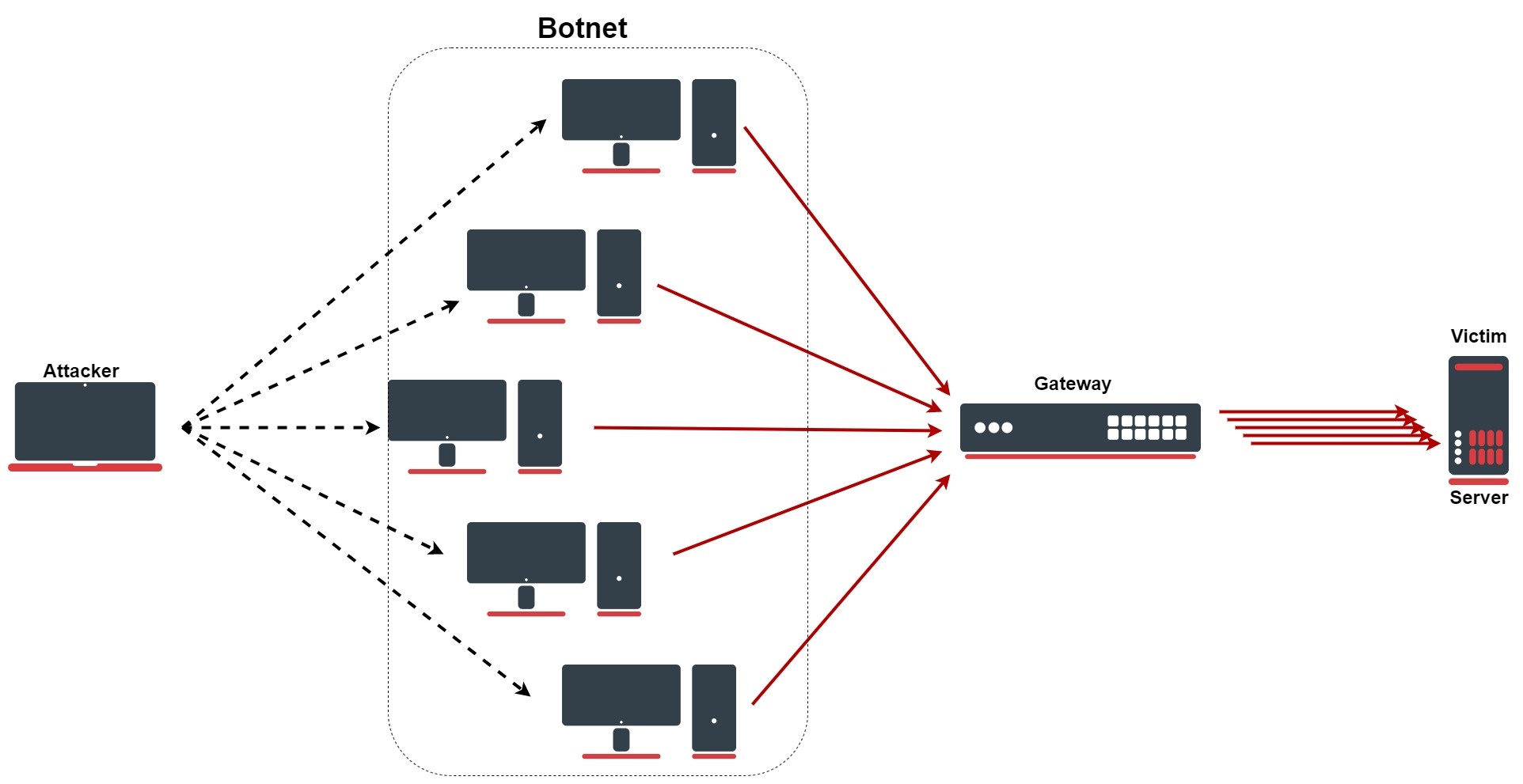
A denial-of-service (DoS) or distributed denial-of-service (DDoS) attack is a malicious attempt to disrupt normal traffic of a targeted server, service, or network by overwhelming the target or its surrounding infrastructure with a flood of Internet traffic. There are several types of DDoS attacks, for example, HTTP flood, SYN flood, DNS amplification, etc.
Protection against DDoS
Configuration lines
These rules are only an improvement for firewall, do not forget to properly secure your device: Building Your First Firewall!
/ip firewall address-list
add list=ddos-attackers
add list=ddos-targets
/ip firewall filter
add action=return chain=detect-ddos dst-limit=32,32,src-and-dst-addresses/10s
add action=add-dst-to-address-list address-list=ddos-targets address-list-timeout=10m chain=detect-ddos
add action=add-src-to-address-list address-list=ddos-attackers address-list-timeout=10m chain=detect-ddos
/ip firewall raw
add action=drop chain=prerouting dst-address-list=ddos-targets src-address-list=ddos-attackers
Configuration Explained
First, we will send every new connection to the specific firewall chain where we will detect DDoS:
/ip/firewall/filter/add chain=forward connection-state=new action=jump jump-target=detect-ddos
In the newly created chain, we will add the following rule with the "dst-limit" parameter. This parameter is written in the following format: dst-limit=count[/time],burst,mode[/expire]. We will match 32 packets with 32 packet burst based on destination and source address flow, which renews every 10 seconds. The rule will work until a given rate is exceeded.
/ip/firewall/filter/add chain=detect-ddos dst-limit=32,32,src-and-dst-addresses/10s action=return
So far all the legitimate traffic should go through the "action=return", but in the case of DoS/DDoS "dst-limit" buffer will be fulfilled and a rule will not "catch" any new traffic. Here come the next rules, which will deal with the attack. Let`s start with creating a list for attackers and victims which we will drop:
ip/firewall/address-list/add list=ddos-attackers
ip/firewall/address-list/add list=ddos-targets
ip/firewall/raw/add chain=prerouting action=drop src-address-list=ddos-attackers dst-address-list=ddos-targets
With the firewall filter section, we will add attackers in the "DDoS-attackers" and victims in list "ddos-targets" list:
/ip/firewall/filter/
add action=add-dst-to-address-list address-list=ddos-targets address-list-timeout=10m chain=detect-ddos
add action=add-src-to-address-list address-list=ddos-attackers address-list-timeout=10m chain=detect-ddos
SYN Attack
SYN Flood
An SYN flood is a form of DoS attack in which an attacker sends a succession of SYN requests to a target's system in an attempt to consume enough server resources to make the system unresponsive to legitimate traffic. Fortunately, in RouterOS we have a specific feature for such an attack:
/ip/settings/set tcp-syncookies=yes
The feature works by sending back ACK packets that contain a little cryptographic hash, which the responding client will echo back with as part of its SYN-ACK packet. If the kernel doesn't see this "cookie" in the reply packet, it will assume the connection is bogus and drop it.
SYN-ACK Flood
An SYN-ACK flood is an attack method that involves sending a target server spoofed SYN-ACK packet at a high rate. The server requires significant resources to process such packets out-of-order (not in accordance with the normal SYN, SYN-ACK, ACK TCP three-way handshake mechanism), it can become so busy handling the attack traffic, that it cannot handle legitimate traffic and hence the attackers achieve a DoS/DDoS condition. In RouterOS, we can configure similar rules from the previously mentioned example, but more specifically for SYN-ACK flood:
/ip/firewall/filter add action=return chain=detect-ddos dst-limit=32,32,src-and-dst-addresses/10s protocol=tcp tcp-flags=syn,ack
Page edited by Guntis G. - "typos"
Here is an example of how to defend against bruteforce attacks on an SSH port. Please note, that ssh allows 3 login attempts per connection, and the address lists are not cleared upon a successful login, so it is possible to blacklist yourself accidentally.
/ip firewall filter
add action=add-src-to-address-list address-list=bruteforce_blacklist address-list-timeout=1d chain=input comment=Blacklist connection-state=new dst-port=22 protocol=tcp src-address-list=connection3
add action=add-src-to-address-list address-list=connection3 address-list-timeout=1h chain=input comment="Third attempt" connection-state=new dst-port=22 protocol=tcp src-address-list=connection2,!secured
add action=add-src-to-address-list address-list=connection2 address-list-timeout=15m chain=input comment="Second attempt" connection-state=new dst-port=22 protocol=tcp src-address-list=connection1
add action=add-src-to-address-list address-list=connection1 address-list-timeout=5m chain=input comment="First attempt" connection-state=new dst-port=22 protocol=tcp
add action=accept chain=input dst-port=22 protocol=tcp src-address-list=!bruteforce_blacklist
If the timeouts were kept at 1min for all three lists - connection1/2/3 - then someone could perform 9 guesses every minute, with the above structure they can do a maximum of 3 guesses per 5min.
Page edited by Guntis G. - "typos"
All available public IP addresses are constantly being port scanned by bots and services like shodan.io and anyone can use this information to perform brute-force attacks and execute any known exploits. Port knocking is a cost-effective way to defend against this by not exposing any ports and simply listening to connection attempts - if the correct sequence of port connection attempts is made, the client is considered safe and added to a list of secured address list that bypass the WAN firewall rules.
Setup example
We are assuming you have already set up a firewall that drops all connection attempts from the WAN port, so you will need to add additional rules before that.
First, create a firewall rule that listens on a given port and adds the connected source IP to an address list - this is the first knock.
/ip/firewall/filter add action=add-src-to-address-list address-list=888 address-list-timeout=30s chain=input dst-port=888 in-interface-list=WAN protocol=tcp
Then add a rule that does the same on another port, but only approves IPs that are already in the first list. You can repeat this step as many times as you like.
/ip/firewall/filter add action=add-src-to-address-list address-list=555 address-list-timeout=30s chain=input dst-port=555 in-interface-list=WAN protocol=tcp src-address-list=888
Finally, the last knock will be added to an IP list that is trusted and any input is accepted.
/ip/firewall/filter add action=add-src-to-address-list address-list=secured address-list-timeout=30m chain=input dst-port=222 in-interface-list=WAN protocol=tcp src-address-list=555
/ip/firewall/filter add action=accept chain=input in-interface-list=WAN src-address-list=secured
Knock to gain access
To access the board from WAN, a port-knocking client could be used, but a simple bash one-liner with nmap can do the job.
for x in 888,555,222; do nmap -p $x -Pn xx.xx.xx.xx; done
Blacklists
Unless you are using a lot of knocks, a simple port scan could accidentally trigger the correct ports in the correct order, so it is advisable to add a blacklist as well.
At the very top of your firewall stack add a drop rule for the blacklist.
/ip/firewall/filter add action=drop chain=input disabled=yes in-interface-list=WAN src-address-list=blacklist
Then add suspicious IPs to the blacklist.
Bad ports - ones that will never be used by a trusted user and hence have a high timeout penalty.
/ip/firewall/filter add action=add-src-to-address-list address-list=blacklist address-list-timeout=1000m chain=input disabled=yes dst-port=666 in-interface-list=WAN protocol=tcp
Ports that slow down the port scanning process significantly to the point where it is pointless, but will never lock out a real user for too long. This could include every single port apart from the 'knock' ports, the key is that the source IP is not already in the secure list and hence those ports can be used after a successful knock.
/ip/firewall/filter add action=add-src-to-address-list address-list=blacklist address-list-timeout=1m chain=input disabled=yes dst-port=21,22,23,8291,10000-60000 in-interface-list=WAN protocol=tcp src-address-list=!secured
Use a passphrase for each knock
You could go even further by sending a passphrase with each knock.
Warning
Layer7 rules are very resource-intensive. Do not use it unless you know what you are doing.
Page edited by Guntis G. - "typos"
Overview
From everything we have learned so far, let's try to build an advanced firewall. In this firewall building example, we will try to use as many firewall features as we can to illustrate how they work and when they should be used the right way.
Most of the filtering will be done in the RAW firewall, a regular firewall will contain just a basic rule set to accept established, related, and untracked connections as well as dropping everything else not coming from LAN to fully protect the router.
Interface Lists
Two interface lists will be used WAN and LAN for easier future management purposes. Interfaces connected to the global internet should be added to the WAN list, in this case, it is ether1!
/interface list
  add comment=defconf name=WAN
  add comment=defconf name=LAN
/interface list member
  add comment=defconf interface=bridge list=LAN
  add comment=defconf interface=ether1 list=WAN
Protect the Device
The main goal here is to allow access to the router only from LAN and drop everything else.
Notice that ICMP is accepted here as well, it is used to accept ICMP packets that passed RAW rules.
/ip firewall filter
  add action=accept chain=input comment="defconf: accept ICMP after RAW" protocol=icmp
  add action=accept chain=input comment="defconf: accept established,related,untracked" connection-state=established,related,untracked
  add action=drop chain=input comment="defconf: drop all not coming from LAN" in-interface-list=!LAN
IPv6 part is a bit more complicated, in addition, UDP traceroute, DHCPv6 client PD, and IPSec (IKE, AH, ESP) are accepted as per RFC recommendations.
/ipv6 firewall filter
add action=accept chain=input comment="defconf: accept ICMPv6 after RAW" protocol=icmpv6
add action=accept chain=input comment="defconf: accept established,related,untracked" connection-state=established,related,untracked
add action=accept chain=input comment="defconf: accept UDP traceroute" dst-port=33434-33534 protocol=udp
add action=accept chain=input comment="defconf: accept DHCPv6-Client prefix delegation." dst-port=546 protocol=udp src-address=fe80::/10
add action=accept chain=input comment="defconf: accept IKE" dst-port=500,4500 protocol=udp
add action=accept chain=input comment="defconf: accept IPSec AH" protocol=ipsec-ah
add action=accept chain=input comment="defconf: accept IPSec ESP" protocol=ipsec-esp
add action=drop chain=input comment="defconf: drop all not coming from LAN" in-interface-list=!LAN
In certain setups where the DHCPv6 relay is used, the src address of the packets may not be from the link-local range. In that case, the src-address parameter of rule #4 must be removed or adjusted to accept the relay address.
Protect the Clients
Before the actual set of rules, let's create a necessary address-list that contains all IPv4/6 addresses that cannot be forwarded.
Notice that in this list multicast address range is added. It is there because in most cases multicast is not used. If you intend to use multicast forwarding, then this address list entry should be disabled.
/ip firewall address-list
  add address=0.0.0.0/8 comment="defconf: RFC6890" list=no_forward_ipv4
  add address=169.254.0.0/16 comment="defconf: RFC6890" list=no_forward_ipv4
  add address=224.0.0.0/4 comment="defconf: multicast" list=no_forward_ipv4
  add address=255.255.255.255/32 comment="defconf: RFC6890" list=no_forward_ipv4
In the same case for IPv6, if multicast forwarding is used then the multicast entry should be disabled from the address-list.
/ipv6 firewall address-list
  add address=fe80::/10  comment="defconf: RFC6890 Linked-Scoped Unicast" list=no_forward_ipv6
  add address=ff00::/8  comment="defconf: multicast" list=no_forward_ipv6
Forward chain will have a bit more rules than input:
- accept established, related and untracked connections;
- FastTrack established and related connections (currently only IPv4);
- drop invalid connections;
- drop bad forward IPs, since we cannot reliably determine in RAW chains which packets are forwarded
- drop connections initiated from the internet (from the WAN side which is not destination NAT`ed);
- drop bogon IPs that should not be forwarded.
We are dropping all non-dstnated IPv4 packets to protect direct attacks on the clients if the attacker knows the internal LAN network. Typically this rule would not be necessary since RAW filters will drop such packets, however, the rule is there for double security in case RAW rules are accidentally messed up.
/ip firewall filter
  add action=accept chain=forward comment="defconf: accept all that matches IPSec policy" ipsec-policy=in,ipsec disabled=yes
  add action=fasttrack-connection chain=forward comment="defconf: fasttrack" connection-state=established,related
  add action=accept chain=forward comment="defconf: accept established,related, untracked" connection-state=established,related,untracked
  add action=drop chain=forward comment="defconf: drop invalid" connection-state=invalid
  add action=drop chain=forward comment="defconf:  drop all from WAN not DSTNATed" connection-nat-state=!dstnat connection-state=new in-interface-list=WAN
  add action=drop chain=forward src-address-list=no_forward_ipv4 comment="defconf: drop bad forward IPs"
  add action=drop chain=forward dst-address-list=no_forward_ipv4 comment="defconf: drop bad forward IPs"
IPv6 forward chain is very similar, except that IPsec and HIP are accepted as per RFC recommendations, and ICMPv6 with hop-limit=1 is dropped.
/ipv6 firewall filter
add action=accept chain=forward comment="defconf: accept established,related,untracked" connection-state=established,related,untracked
add action=drop chain=forward comment="defconf: drop invalid" connection-state=invalid
add action=drop chain=forward src-address-list=no_forward_ipv6 comment="defconf: drop bad forward IPs"
add action=drop chain=forward dst-address-list=no_forward_ipv6 comment="defconf: drop bad forward IPs"
add action=drop chain=forward comment="defconf: rfc4890 drop hop-limit=1" hop-limit=equal:1 protocol=icmpv6
add action=accept chain=forward comment="defconf: accept ICMPv6 after RAW" protocol=icmpv6
add action=accept chain=forward comment="defconf: accept HIP" protocol=139
add action=accept chain=forward comment="defconf: accept IKE" protocol=udp dst-port=500,4500
add action=accept chain=forward comment="defconf: accept AH" protocol=ipsec-ah
add action=accept chain=forward comment="defconf: accept ESP" protocol=ipsec-esp
add action=accept chain=forward comment="defconf: accept all that matches IPSec policy" ipsec-policy=in,ipsec
add action=drop chain=forward comment="defconf: drop everything else not coming from LAN" in-interface-list=!LAN
Notice the IPsec policy matcher rules. It is very important that IPsec encapsulated traffic bypass fast-track. That is why as an illustration we have added a disabled rule to accept traffic matching IPsec policies. Whenever IPsec tunnels are used on the router this rule should be enabled. For IPv6 it is much more simple since it does not have fast-track support.
Another approach to solving the IPsec problem is to add RAW rules, we will talk about this method later in the RAW section
Masquerade Local Network
For local devices behind the router to be able to access the internet, local networks must be masqueraded. In most cases, it is advised to use src-nat instead of masquerade, however in this case when the WAN address is dynamic it is the only option.
/ip firewall nat
  add action=accept chain=srcnat comment="defconf: accept all that matches IPSec policy" ipsec-policy=out,ipsec disabled=yes
  add action=masquerade chain=srcnat comment="defconf: masquerade" out-interface-list=WAN
Notice the disabled policy matcher rule, the same as in firewall filters IPSec traffic must be excluded from being NATed (except in specific scenarios where IPsec policy is configured to match NAT`ed address). So whenever IPsec tunnels are used on the router this rule must be enabled.
RAW Filtering
IPv4 Address Lists
Before setting RAW rules, let's create some address lists necessary for our filtering policy. RFC 6890 will be used as a reference.
First, address-list contains all IPv4 addresses that cannot be used as src/dst/forwarded, etc. (will be dropped immediately if such address is seen)
/ip firewall address-list
  add address=127.0.0.0/8 comment="defconf: RFC6890" list=bad_ipv4
  add address=192.0.0.0/24 comment="defconf: RFC6890" list=bad_ipv4
  add address=192.0.2.0/24 comment="defconf: RFC6890 documentation" list=bad_ipv4
  add address=198.51.100.0/24 comment="defconf: RFC6890 documentation" list=bad_ipv4
  add address=203.0.113.0/24 comment="defconf: RFC6890 documentation" list=bad_ipv4
  add address=240.0.0.0/4 comment="defconf: RFC6890 reserved" list=bad_ipv4
Another address list contains all IPv4 addresses that cannot be routed globally.
/ip firewall address-list
  add address=0.0.0.0/8 comment="defconf: RFC6890" list=not_global_ipv4
  add address=10.0.0.0/8 comment="defconf: RFC6890" list=not_global_ipv4
  add address=100.64.0.0/10 comment="defconf: RFC6890" list=not_global_ipv4
  add address=169.254.0.0/16 comment="defconf: RFC6890" list=not_global_ipv4
  add address=172.16.0.0/12 comment="defconf: RFC6890" list=not_global_ipv4
  add address=192.0.0.0/29 comment="defconf: RFC6890" list=not_global_ipv4
  add address=192.168.0.0/16 comment="defconf: RFC6890" list=not_global_ipv4
  add address=198.18.0.0/15 comment="defconf: RFC6890 benchmark" list=not_global_ipv4
  add address=255.255.255.255/32 comment="defconf: RFC6890" list=not_global_ipv4
And last two address lists for addresses that cannot be as destination or source address.
/ip firewall address-list
  add address=224.0.0.0/4 comment="defconf: multicast" list=bad_src_ipv4
  add address=255.255.255.255/32 comment="defconf: RFC6890" list=bad_src_ipv4
add address=0.0.0.0/8 comment="defconf: RFC6890" list=bad_dst_ipv4
  add address=224.0.0.0/4 comment="defconf: RFC6890" list=bad_dst_ipv4
IPv4 RAW Rules
Raw IPv4 rules will perform the following actions:
- add disabled "accept" rule - can be used to quickly disable RAW filtering without disabling all RAW rules;
- accept DHCP discovery - most of the DHCP packets are not seen by an IP firewall, but some of them are, so make sure that they are accepted;
- drop packets that use bogon IPs;
- drop from invalid SRC and DST IPs;
- drop globally unroutable IPs coming from WAN;
- drop packets with source-address not equal to 192.168.88.0/24 (default IP range) coming from LAN;
- drop packets coming from WAN to be forwarded to 192.168.88.0/24 network, this will protect from attacks if the attacker knows the internal network;
- drop bad ICMP, UDP, and TCP;
- accept everything else coming from WAN and LAN;
- drop everything else, to make sure that any newly added interface (like PPPoE connection to service provider) is protected against accidental misconfiguration.
/ip firewall raw
add action=accept chain=prerouting comment="defconf: enable for transparent firewall" disabled=yes
add action=accept chain=prerouting comment="defconf: accept DHCP discover" dst-address=255.255.255.255 dst-port=67 in-interface-list=LAN protocol=udp src-address=0.0.0.0 src-port=68
add action=drop chain=prerouting comment="defconf: drop bogon IP's" src-address-list=bad_ipv4
add action=drop chain=prerouting comment="defconf: drop bogon IP's" dst-address-list=bad_ipv4
add action=drop chain=prerouting comment="defconf: drop bogon IP's" src-address-list=bad_src_ipv4
add action=drop chain=prerouting comment="defconf: drop bogon IP's" dst-address-list=bad_dst_ipv4
add action=drop chain=prerouting comment="defconf: drop non global from WAN" src-address-list=not_global_ipv4 in-interface-list=WAN
add action=drop chain=prerouting comment="defconf: drop forward to local lan from WAN" in-interface-list=WAN dst-address=192.168.88.0/24
add action=drop chain=prerouting comment="defconf: drop local if not from default IP range" in-interface-list=LAN src-address=!192.168.88.0/24
add action=drop chain=prerouting comment="defconf: drop bad UDP" port=0 protocol=udp
add action=jump chain=prerouting comment="defconf: jump to ICMP chain" jump-target=icmp4 protocol=icmp
add action=jump chain=prerouting comment="defconf: jump to TCP chain" jump-target=bad_tcp protocol=tcp
add action=accept chain=prerouting comment="defconf: accept everything else from LAN" in-interface-list=LAN
add action=accept chain=prerouting comment="defconf: accept everything else from WAN" in-interface-list=WAN
add action=drop chain=prerouting comment="defconf: drop the rest"
Notice that we used some optional chains, the first TCP chain to drop TCP packets known to be invalid.
/ip firewall raw
add action=drop chain=bad_tcp comment="defconf: TCP flag filter" protocol=tcp tcp-flags=!fin,!syn,!rst,!ack
add action=drop chain=bad_tcp comment=defconf protocol=tcp tcp-flags=fin,syn
add action=drop chain=bad_tcp comment=defconf protocol=tcp tcp-flags=fin,rst
add action=drop chain=bad_tcp comment=defconf protocol=tcp tcp-flags=fin,!ack
add action=drop chain=bad_tcp comment=defconf protocol=tcp tcp-flags=fin,urg
add action=drop chain=bad_tcp comment=defconf protocol=tcp tcp-flags=syn,rst
add action=drop chain=bad_tcp comment=defconf protocol=tcp tcp-flags=rst,urg
add action=drop chain=bad_tcp comment="defconf: TCP port 0 drop" port=0 protocol=tcp
And another chain for ICMP. Note that if you want a very strict firewall then such strict ICMP filtering can be used, but in most cases, it is not necessary and simply adds more load on the router's CPU. ICMP rate limit in most cases is also unnecessary since the Linux kernel is already limiting ICMP packets to 100pps.
/ip firewall raw
add action=accept chain=icmp4 comment="defconf: echo reply" icmp-options=0:0 limit=5,10:packet protocol=icmp
add action=accept chain=icmp4 comment="defconf: net unreachable" icmp-options=3:0 protocol=icmp
add action=accept chain=icmp4 comment="defconf: host unreachable" icmp-options=3:1 protocol=icmp
add action=accept chain=icmp4 comment="defconf: protocol unreachable" icmp-options=3:2 protocol=icmp
add action=accept chain=icmp4 comment="defconf: port unreachable" icmp-options=3:3 protocol=icmp
add action=accept chain=icmp4 comment="defconf: fragmentation needed" icmp-options=3:4 protocol=icmp
add action=accept chain=icmp4 comment="defconf: echo" icmp-options=8:0 limit=5,10:packet protocol=icmp
add action=accept chain=icmp4 comment="defconf: time exceeded " icmp-options=11:0-255 protocol=icmp
add action=drop chain=icmp4 comment="defconf: drop other icmp" protocol=icmp
IPv6 Address Lists
List of IPv6 addresses that should be dropped instantly
/ipv6 firewall address-list
add address=::1/128 comment="defconf: RFC6890 lo" list=bad_ipv6
add address=::ffff:0:0/96 comment="defconf: RFC6890 IPv4 mapped" list=bad_ipv6
add address=2001::/23 comment="defconf: RFC6890" list=bad_ipv6
add address=2001:db8::/32 comment="defconf: RFC6890 documentation" list=bad_ipv6
add address=2001:10::/28 comment="defconf: RFC6890 orchid" list=bad_ipv6
add address=::/96 comment="defconf: ipv4 compat" list=bad_ipv6
List of IPv6 addresses that are not globally routable
/ipv6 firewall address-list
add address=100::/64 comment="defconf: RFC6890 Discard-only" list=not_global_ipv6
add address=2001::/32 comment="defconf: RFC6890 TEREDO" list=not_global_ipv6
add address=2001:2::/48 comment="defconf: RFC6890 Benchmark" list=not_global_ipv6
add address=fc00::/7 comment="defconf: RFC6890 Unique-Local" list=not_global_ipv6
List of addresses as an invalid destination address
/ipv6 firewall address-list add address=::/128 comment="defconf: unspecified" list=bad_dst_ipv6
List of addresses as an invalid source address
/ipv6 firewall address-list
  add address=::/128 comment="defconf: unspecified" list=bad_src_ipv6
  add address=ff00::/8  comment="defconf: multicast" list=bad_src_ipv6
IPv6 RAW Rules
Raw IPv6 rules will perform the following actions:
- add disabled accept rule - can be used to quickly disable RAW filtering without disabling all RAW rules;
- drop packets that use bogon IPs;
- drop from invalid SRC and DST IPs;
- drop globally unroutable IPs coming from WAN;
- drop bad ICMP;
- accept everything else coming from WAN and LAN;
- drop everything else, to make sure that any newly added interface (like PPPoE connection to service provider) is protected against accidental misconfiguration.
/ipv6 firewall raw
add action=accept chain=prerouting comment="defconf: enable for transparent firewall" disabled=yes
add action=accept chain=prerouting comment="defconf: RFC4291, section 2.7.1" src-address=::/128 dst-address=ff02:0:0:0:0:1:ff00::/104 icmp-options=135 protocol=icmpv6
add action=drop chain=prerouting comment="defconf: drop bogon IP's" src-address-list=bad_ipv6
add action=drop chain=prerouting comment="defconf: drop bogon IP's" dst-address-list=bad_ipv6
add action=drop chain=prerouting comment="defconf: drop packets with bad SRC ipv6" src-address-list=bad_src_ipv6
add action=drop chain=prerouting comment="defconf: drop packets with bad dst ipv6" dst-address-list=bad_dst_ipv6
add action=drop chain=prerouting comment="defconf: drop non global from WAN" src-address-list=not_global_ipv6 in-interface-list=WAN
add action=jump chain=prerouting comment="defconf: jump to ICMPv6 chain" jump-target=icmp6 protocol=icmpv6
add action=accept chain=prerouting comment="defconf: accept local multicast scope" dst-address=ff02::/16
add action=drop chain=prerouting comment="defconf: drop other multicast destinations" dst-address=ff00::/8
add action=accept chain=prerouting comment="defconf: accept everything else from WAN" in-interface-list=WAN
add action=accept chain=prerouting comment="defconf: accept everything else from LAN" in-interface-list=LAN
add action=drop chain=prerouting comment="defconf: drop the rest"
Notice that the optional ICMP chain was used. If you want a very strict firewall then such strict ICMP filtering can be used, but in most cases, it is not necessary and simply adds more load on the router's CPU. ICMP rate limit in most cases is also unnecessary since the Linux kernel is already limiting ICMP packets to 100pps
/ipv6 firewall raw
# Be aware that different operating systems originate packets with different default TTL values
add action=drop chain=icmp6 comment="defconf: rfc4890 drop ll if hop-limit!=255" dst-address=fe80::/10 hop-limit=not-equal:255 protocol=icmpv6
add action=accept chain=icmp6 comment="defconf: dst unreachable" icmp-options=1:0-255 protocol=icmpv6
add action=accept chain=icmp6 comment="defconf: packet too big" icmp-options=2:0-255 protocol=icmpv6
add action=accept chain=icmp6 comment="defconf: limit exceeded" icmp-options=3:0-1 protocol=icmpv6
add action=accept chain=icmp6 comment="defconf: bad header" icmp-options=4:0-2 protocol=icmpv6
add action=accept chain=icmp6 comment="defconf: Mobile home agent address discovery" icmp-options=144:0-255 protocol=icmpv6
add action=accept chain=icmp6 comment="defconf: Mobile home agent address discovery" icmp-options=145:0-255 protocol=icmpv6
add action=accept chain=icmp6 comment="defconf: Mobile prefix solic" icmp-options=146:0-255 protocol=icmpv6
add action=accept chain=icmp6 comment="defconf: Mobile prefix advert" icmp-options=147:0-255 protocol=icmpv6
add action=accept chain=icmp6 comment="defconf: echo request limit 5,10" icmp-options=128:0-255 limit=5,10:packet protocol=icmpv6
add action=accept chain=icmp6 comment="defconf: echo reply limit 5,10" icmp-options=129:0-255 limit=5,10:packet protocol=icmpv6
add action=accept chain=icmp6 comment="defconf: rfc4890 router solic limit 5,10 only LAN" hop-limit=equal:255 icmp-options=133:0-255 in-interface-list=LAN limit=5,10:packet protocol=icmpv6
add action=accept chain=icmp6 comment="defconf: rfc4890 router advert limit 5,10 only LAN" hop-limit=equal:255 icmp-options=134:0-255 in-interface-list=LAN limit=5,10:packet protocol=icmpv6
add action=accept chain=icmp6 comment="defconf: rfc4890 neighbor solic limit 5,10 only LAN" hop-limit=equal:255 icmp-options=135:0-255 in-interface-list=LAN limit=5,10:packet protocol=icmpv6
add action=accept chain=icmp6 comment="defconf: rfc4890 neighbor advert limit 5,10 only LAN" hop-limit=equal:255 icmp-options=136:0-255 in-interface-list=LAN limit=5,10:packet protocol=icmpv6
add action=accept chain=icmp6 comment="defconf: rfc4890 inverse ND solic limit 5,10 only LAN" hop-limit=equal:255 icmp-options=141:0-255 in-interface-list=LAN limit=5,10:packet protocol=icmpv6
add action=accept chain=icmp6 comment="defconf: rfc4890 inverse ND advert limit 5,10 only LAN" hop-limit=equal:255 icmp-options=142:0-255 in-interface-list=LAN limit=5,10:packet protocol=icmpv6
add action=drop chain=icmp6 comment="defconf: drop other icmp" protocol=icmpv6
Page edited by Guntis G. - "typos"
Overview
We strongly suggest keeping the default firewall on. Here are a few adjustments to make it more secure. Make sure you configure additional changes when you completely understand the benefit of these particular firewall rules.
To see the default firewall rules through the CLI you can type:
/system default-configuration print
IPv4 firewall
Protect the router itself
- work with
newconnections to decrease the load on a router; - create
address-listfor IP addresses, that are allowed to access your router; - enable ICMP access (optionally);
dropeverything else,log=yesmight be added to log packets that hit the specific rule;
/ip firewall filter
add action=accept chain=input comment="default configuration" connection-state=established,related
add action=accept chain=input src-address-list=allowed_to_router
add action=accept chain=input protocol=icmp
add action=drop chain=input
/ip firewall address-list
add address=192.168.88.2-192.168.88.254 list=allowed_to_router
Protect the LAN devices
We will create address-list with the name "not_in_internet" which we will use for the firewall filter rules:
/ip firewall address-list
add address=0.0.0.0/8 comment=RFC6890 list=not_in_internet
add address=172.16.0.0/12 comment=RFC6890 list=not_in_internet
add address=192.168.0.0/16 comment=RFC6890 list=not_in_internet
add address=10.0.0.0/8 comment=RFC6890 list=not_in_internet
add address=169.254.0.0/16 comment=RFC6890 list=not_in_internet
add address=127.0.0.0/8 comment=RFC6890 list=not_in_internet
add address=224.0.0.0/4 comment=Multicast list=not_in_internet
add address=198.18.0.0/15 comment=RFC6890 list=not_in_internet
add address=192.0.0.0/24 comment=RFC6890 list=not_in_internet
add address=192.0.2.0/24 comment=RFC6890 list=not_in_internet
add address=198.51.100.0/24 comment=RFC6890 list=not_in_internet
add address=203.0.113.0/24 comment=RFC6890 list=not_in_internet
add address=100.64.0.0/10 comment=RFC6890 list=not_in_internet
add address=240.0.0.0/4 comment=RFC6890 list=not_in_internet
add address=192.88.99.0/24 comment="6to4 relay Anycast [RFC 3068]" list=not_in_internet
Brief firewall filter rule explanation:
- packets with connection-state=established,related added to FastTrack for faster data throughput, the firewall will work with new connections only;
- drop invalid connection and log them with prefix "invalid";
- drop attempts to reach not public addresses from your local network, apply address-list=not_in_internet before, "bridge" is local network interface, log=yes attempts with prefix "!public_from_LAN";
- drop incoming packets that are not NAT`ed, ether1 is public interface, log attempts with "!NAT" prefix;
- jump to ICMP chain to drop unwanted ICMP messages
- drop incoming packets from the Internet, which are not public IP addresses, ether1 is a public interface, log attempts with prefix "!public";
- drop packets from LAN that does not have LAN IP, 192.168.88.0/24 is local network used subnet;
/ip firewall filter
add action=fasttrack-connection chain=forward comment=FastTrack connection-state=established,related
add action=accept chain=forward comment="Established, Related" connection-state=established,related
add action=drop chain=forward comment="Drop invalid" connection-state=invalid log=yes log-prefix=invalid
add action=drop chain=forward comment="Drop tries to reach not public addresses from LAN" dst-address-list=not_in_internet in-interface=bridge log=yes log-prefix=!public_from_LAN out-interface=!bridge
add action=drop chain=forward comment="Drop incoming packets that are not NAT`ted" connection-nat-state=!dstnat connection-state=new in-interface=ether1 log=yes log-prefix=!NAT
add action=jump chain=forward protocol=icmp jump-target=icmp comment="jump to ICMP filters"
add action=drop chain=forward comment="Drop incoming from internet which is not public IP" in-interface=ether1 log=yes log-prefix=!public src-address-list=not_in_internet
add action=drop chain=forward comment="Drop packets from LAN that do not have LAN IP" in-interface=bridge log=yes log-prefix=LAN_!LAN src-address=!192.168.88.0/24
Allow only needed ICMP codes in "icmp" chain:
/ip firewall filter
  add chain=icmp protocol=icmp icmp-options=0:0 action=accept \
    comment="echo reply"
  add chain=icmp protocol=icmp icmp-options=3:0 action=accept \
    comment="net unreachable"
  add chain=icmp protocol=icmp icmp-options=3:1 action=accept \
    comment="host unreachable"
  add chain=icmp protocol=icmp icmp-options=3:4 action=accept \
    comment="host unreachable fragmentation required"
  add chain=icmp protocol=icmp icmp-options=8:0 action=accept \
    comment="allow echo request"
  add chain=icmp protocol=icmp icmp-options=11:0 action=accept \
    comment="allow time exceed"
  add chain=icmp protocol=icmp icmp-options=12:0 action=accept \
    comment="allow parameter bad"
  add chain=icmp action=drop comment="deny all other types"
IPv6 firewall
Protect the router itself
Create an address-list from which you allow access to the device:
/ipv6 firewall address-list add address=fd12:672e:6f65:8899::/64 list=allowed
Brief IPv6 firewall filter rule explanation:
- work with new packets, accept established/related packets;
- drop link-local addresses from Internet(public) interface/interface-list;
- accept access to a router from link-local addresses, accept multicast addresses for management purposes, accept your source address-list for router access;
- drop anything else;
/ipv6 firewall filter
add action=accept chain=input comment="allow established and related" connection-state=established,related
add chain=input action=accept protocol=icmpv6 comment="accept ICMPv6"
add chain=input action=accept protocol=udp port=33434-33534 comment="defconf: accept UDP traceroute"
add chain=input action=accept protocol=udp dst-port=546 src-address=fe80::/10 comment="accept DHCPv6-Client prefix delegation."
add action=drop chain=input in-interface=in_interface_name log=yes log-prefix=dropLL_from_public src-address=fe80::/10
add action=accept chain=input comment="allow allowed addresses" src-address-list=allowed
add action=drop chain=input
/ipv6 firewall address-list
add address=fe80::/16 list=allowed
add address=xxxx::/48 list=allowed
add address=ff02::/16 comment=multicast list=allowed
In certain setups where the DHCPv6 relay is used, the src address of the packets may not be from the link-local range. In that case, the src-address parameter of rule #4 must be removed or adjusted to accept the relay address.
Protect the LAN devices
Enabled IPv6 makes your clients available from public networks, make sure to add proper firewall filter rules to protect your customers.
- accept established/related and work with new packets;
- drop invalid packets and put prefix for rules;
- accept ICMP packets;
- accept new connection from your clients to the Internet;
- drop everything else.
/ipv6 firewall filter
add action=accept chain=forward comment=established,related connection-state=established,related
add action=drop chain=forward comment=invalid connection-state=invalid log=yes log-prefix=ipv6,invalid
add action=accept chain=forward comment=icmpv6 in-interface=!in_interface_name protocol=icmpv6
add action=accept chain=forward comment="local network" in-interface=!in_interface_name src-address-list=allowed
add action=drop chain=forward log-prefix=IPV6
Page edited by Guntis G. - "typos"
Overview
The following steps are a recommendation on how to additionally protect your device with already configured strong firewall rules.
RouterOS version
Start by upgrading your RouterOS version. Some older releases have had certain weaknesses or vulnerabilities, that have been fixed. Keep your device up to date, to be sure it is secure. Click "check for updates" in WinBox or WebFig, to upgrade. We suggest you follow announcements on our security announcement blog to be informed about any new security issues.
Access to a router
Access username
Change the default username admin to a different name. A custom name helps to protect access to your router if anybody has direct access to your router:
/user add name=myname password=mypassword group=full
/user disable admin
Access password
MikroTik routers require password configuration, we suggest using a password generator tool to create secure and non-repeating passwords. With a secure password, we mean:
- Minimum 12 characters;
- Include numbers, Symbols, Capital and lowercase letters;
- Is not a Dictionary Word or a Combination of Dictionary Words;
/user set myname password="!={Ba3N!"40TуX+GvKBz?jTLIUcx/," RouterOS MAC-access
RouterOS has built-in options for easy management access to network devices. The particular services should be shut down on production networks: MAC-Telnet, MAC-WinBox, and MAC-Ping:
/tool mac-server set allowed-interface-list=none
/tool mac-server mac-winbox set allowed-interface-list=none
/tool mac-server ping set enabled=no
Neighbor Discovery
MikroTik Neighbor discovery protocol is used to show and recognize other MikroTik routers in the network, and disable neighbor discovery on all interfaces:
/ip neighbor discovery-settings set discover-interface-list=none
Bandwidth server
A bandwidth server is used to test throughput between two MikroTik routers. Disable it in the production environment:
/tool bandwidth-server set enabled=no
DNS cache
A router might have DNS cache enabled, which decreases the resolving time for DNS requests from clients to remote servers. In case DNS cache is not required on your router or another router is used for such purposes, disable it:
/ip dns set allow-remote-requests=no
Other clients services
RouterOS might have other services enabled (they are disabled by default RouterOS configuration). MikroTik caching proxy, socks, UPnP, and cloud services:
/ip proxy set enabled=no
/ip socks set enabled=no
/ip upnp set enabled=no
/ip cloud set ddns-enabled=no update-time=no
More Secure SSH access
It is possible to enable more strict SSH settings (add aes-128-ctr and disallow hmac sha1 and groups with sha1) with this command:
/ip ssh set strong-crypto=yes
Router interface
Ethernet/SFP interfaces
It is good practice to disable all unused interfaces on your router, to decrease unauthorized access to your router:
/interface print
/interface set X disabled=yes
Where X numbers of unused interfaces.
LCD
Some RouterBOARDs have an LCD module for informational purposes, set a pin:
/lcd/pin/set pin-number=3659 hide-pin-number=yes
or disable it:
/lcd/set enabled=no
Page edited by Serhii T.
Overview
This article describes a set of commands used for configuration management.
Configuration Undo and Redo
Any action done in the GUI or any command executed from the CLI is recorded in /system history. You can undo or redo any action by running undo or redo commands from the CLI or by clicking on Undo, and Redo buttons from the GUI.
A simple example to demonstrate the addition of the firewall rule and how to undo and redo the action:
[admin@v7_ccr_bgp] /ip/firewall/filter> add chain=forward action=drop

[admin@v7_ccr_bgp] /ip/firewall/filter> print
Flags: X - disabled, I - invalid; D - dynamic
0 X chain=input action=drop protocol=icmp src-address=10.155.101.1 log=no
log-prefix=""

1 chain=forward action=drop

[admin@v7_ccr_bgp] /ip/firewall/filter> /system/history/print
Flags: U - undoable, R - redoable, F - floating-undo
Columns: ACTION, BY, POLICy
ACTION BY POLIC
F filter rule added admin write
U --- write
[admin@v7_ccr_bgp] /ip/firewall/filter>
We have added a firewall rule and in /system history we can see all that was done.
Let's undo everything:
[admin@v7_ccr_bgp] /ip/firewall/filter> /undo
[admin@v7_ccr_bgp] /ip/firewall/filter> print
Flags: X - disabled, I - invalid; D - dynamic
0 X chain=input action=drop protocol=icmp src-address=10.155.101.1 log=no
log-prefix=""

[admin@v7_ccr_bgp] /ip/firewall/filter>
As you can see firewall rule disappeared.
Now redo the last change:
[admin@v7_ccr_bgp] /ip/firewall/filter> /redo
[admin@v7_ccr_bgp] /ip/firewall/filter> print
Flags: X - disabled, I - invalid; D - dynamic
0 X chain=input action=drop protocol=icmp src-address=10.155.101.1 log=no
log-prefix=""

1 chain=forward action=drop

[admin@v7_ccr_bgp] /ip/firewall/filter>
System history is capable of showing exact CLI commands that will be executed during "Undo" or "Redo" actions even if we perform the action from GUI, for example, detailed history output after adding TCP accept rule from WinBox:
[admin@v7_ccr_bgp] /system/history> print detail
Flags: U - undoable, R - redoable, F - floating-undo
 F redo=
      /ip firewall filter add action=accept chain=forward disabled=no log=no \
          log-prefix="" protocol=tcp
    undo=/ip firewall filter remove *4 action="filter rule added" by="admin"
    policy=write time=oct/10/2019 18:51:05

 F redo=/ip firewall filter add action=accept chain=forward
    undo=/ip firewall filter remove *3 action="filter rule added" by="admin"
    policy=write time=oct/10/2019 18:49:03


U redo="" undo="" action="---" by="" policy=write time=sep/27/2019 13:07:35
[admin@v7_ccr_bgp] /system/history>
Safe Mode
It is sometimes possible to change router configuration in a way that will make the router inaccessible (except from the local console). Usually, this is done by accident, but there is no way to undo the last change when the connection to the router is already cut. Safe mode can be used to minimize such risk.
The "Safe Mode" button in the Winbox GUI allows you to enter Safe Mode, while in the CLI, you can access it by either using the keyboard shortcut F4 or pressing [CTRL]+[X]. To exit without saving the made changes in CLI, hit [CTRL]+[D].
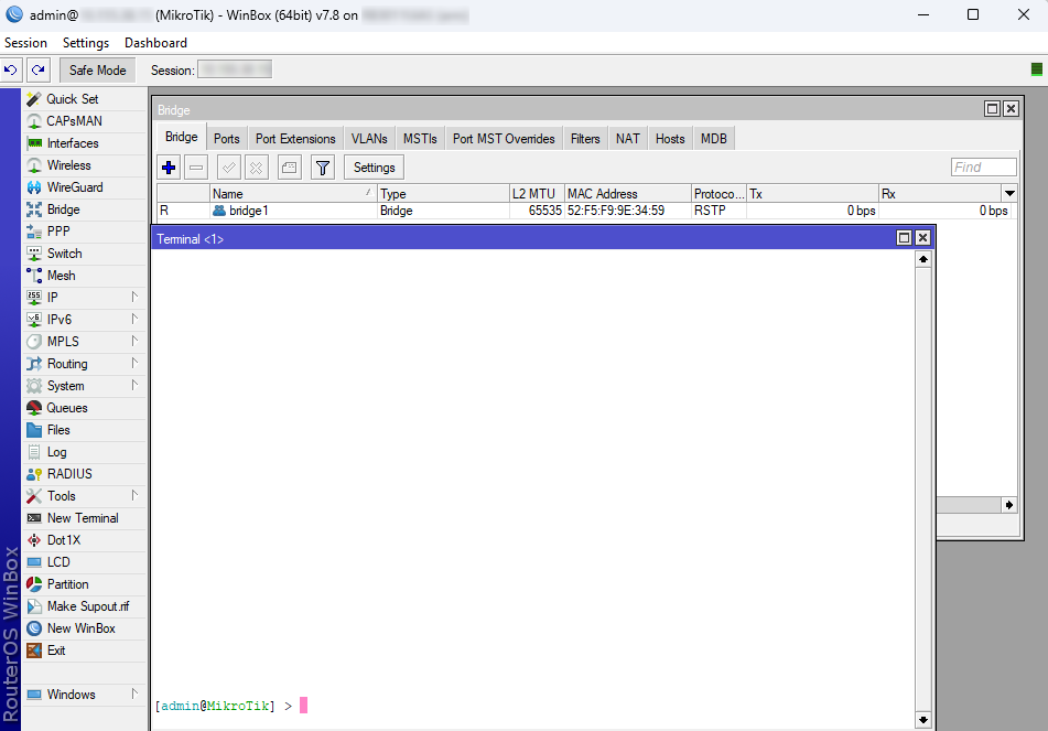
[admin@MikroTik] ip route>[CTRL]+[X]
[Safe Mode taken]
[admin@MikroTik] ip route<SAFE>
Message Safe Mode taken is displayed and prompt changes to reflect that session is now in safe mode. All configuration changes that are made (also from other login sessions), while the router is in safe mode, are automatically undone if the safe mode session terminates abnormally. You can see all such changes that will be automatically undone and tagged with an F flag in the system history:
[admin@MikroTik] /ip/route>
[Safe Mode taken]
[admin@MikroTik] /ip/route<SAFE> add
[admin@MikroTik] /ip/route<SAFE> /system/history/print
Flags: U, F - FLOATING-UNDO
Columns:
 ACTION, BY, POLICY ACTION BY POLICY
F route 0.0.0.0/0 added admin write
Now, if the telnet connection (or WinBox terminal) is cut, then after a while (TCP timeout is 9 minutes) all changes that were made while in safe mode will be undone. Exiting session by [Ctrl]+[D] also undoes all safe mode changes, while /quit does not.
If another user tries to enter safe mode, he's given the following message:
[admin@MikroTik] >
Hijacking Safe Mode from someone - unroll/release/don't take it [u/r/d]:
- [u] - undoes all safe mode changes, and puts the current session in safe mode.
- [r] - keeps all current safe mode changes, and puts the current session in a safe mode. The previous owner of safe mode is notified about this:
[admin@MikroTik] ip firewall rule input
[Safe mode released by another user]
- [d] - leaves everything as-is.
If too many changes are made while in safe mode, and there's no room in history to hold them all (currently history keeps up to 100 most recent actions), then the session is automatically put out of the safe mode, and no changes are automatically undone. Thus, it is best to change the configuration in small steps, while in safe mode. Pressing [Ctrl]+[X] twice is an easy way to empty the safe mode action list.
System Backup and Restore
System backup is the way to completely clone router configuration in binary format.
More information about Backup and Restore is found here.
Configuration Export and Import
RouterOS allows exporting and importing parts of the configuration in plain text format. This method can be used to copy bits of configuration between different devices, for example, clone the whole firewall from one router to another.
An export command can be executed from each menu (resulting in configuration export only from this specific menu and all its sub-menus) or from the root menu for complete config export and is available for CLI only.
The Export command does not export system user passwords, installed certificates, SSH keys, Dude, or a User-manager database.
Installed certificates, Dude, and User-manager databases must be manually exported and imported into a new device.
System user passwords and user SSH keys can not be exported.
During config import, we suggest using the same RouterOS version used during config export to prevent cases when some of the commands do not exist in one or another RouterOS version.
Configuration Export
The following command parameters are accepted:
| Property | Description |
|---|---|
| compact | Output only modified configuration, the default behavior |
| file | Export configuration to a specified file. When the file is not specified export output will be printed to the terminal |
show-sensitive (yes|no; Default: no). RouterOS version 7 only hide-sensitive (yes|no; Default: no). RouterOS version 6 only | Show sensitive information, like passwords, keys, etc. Hide sensitive information, like passwords, keys, etc. |
| terse | With this parameter, the export command will output only configuration parameters, without defaults. |
| verbose | With this parameter, the export command will output whole configuration parameters and items including defaults. |
For example, export configuration from /ip address the menu and save it to a file:
    [admin@MikroTik] > /ip address print
    Flags: X - disabled, I - invalid, D - dynamic
    #   ADDRESS            NETWORK         BROADCAST       INTERFACE
    0   10.1.0.172/24      10.1.0.0        10.1.0.255      bridge1
    1   10.5.1.1/24        10.5.1.0        10.5.1.255      ether1
    [admin@MikroTik] > /ip address export file=address
    [admin@MikroTik] > /file print
    # NAME                            TYPE         SIZE       CREATION-TIME
    0  address.rsc                     script       315        dec/23/2003 13:21:48
    [admin@MikroTik] >
By default, the export command writes only user-edited configuration, RouterOS defaults are omitted.
For example, the IPSec default policy will not be exported, and if we change one property then only our change will be exported:
    [admin@rack1_b4] /ip ipsec policy> print
    Flags: T - template, X - disabled, D - dynamic, I - inactive, * - default
    0 T * group=default src-address=::/0 dst-address=::/0 protocol=all
          proposal=default template=yes
    [admin@rack1_b4] /ip ipsec policy> export
    # apr/02/1970 17:59:14 by RouterOS 6.22
    # software id = DB0D-LK67
    #
    [admin@rack1_b4] /ip ipsec policy> set 0 protocol=gre
    [admin@rack1_b4] /ip ipsec policy> export
    # apr/02/1970 17:59:30 by RouterOS 6.22
    # software id = DB0D-LK67
    #
    /ip ipsec policy
    set 0 protocol=gre
Note:
The * flag, indicates that the entry is system default and cannot be removed manually.
Here is the list of all menus containing default system entries
| Menu | Default Entry |
|---|---|
| /interface wireless security-profiles | default |
| /ppp profile | "default", "default-encryption" |
| /ip hotspot profile | default |
| /ip hotspot user profile | default |
| /ip ipsec policy | default |
| /ip ipsec policy group | default |
| /ip ipsec proposal | default |
| /ip ipsec mode-conf | read-only |
| /ip smb shares | pub |
| /ip smb users | guest |
| /ipv6 nd | any |
| /mpls interface | all |
| /routing bfd interface | all |
| /routing bgp instance | default |
| /routing ospf instance | default |
| /routing ospf area | backbone |
| /routing ospf-v3 instance | defailt |
| /routing ospf-v3 area | backbone |
| /snmp community | public |
| /tool mac-server mac-winbox | all |
| /tool mac-server | all |
| /system logging | "info", "error", "warning", "critical" |
| /system logging action | "memory", "disk", "echo", "remote" |
| /queue type | "default", "ethernet-default", "wireless-default", "synchronous-default", "hotspot-default", "only-hardware-queue", "multi-queue-ethernet-default", "default-small" |
If some specific menu will not be able to respond to the export command, starting from the RouterOS v7.11, an error message will be printed out in the export command output after a timeout ("#error exporting "/xxx" (timeout)") and the process will move on to the next menu.
Starting from RouterOS 7.13, you can export parts of a specific menu. For instance, it is possible to export a specific address-list among multiple address-lists on your router.
[admin@MikroTik] > ip firewall address-list export where list=mylist
Configuration Import
Root menu command import allows running configuration script from the specified file. Script file (with extension ".rsc") can contain any console command including complex scripts.
For example, load saved configuration file
[admin@MikroTik] > import address.rsc
Opening script file address.rsc

Script file loaded and executed successfully
[admin@MikroTik] >
Import command allows to specify the following parameters:
| Property | Description |
|---|---|
| from-line | Start executing the script from the specified line number |
| file-name | Name of the script (.rsc) file to be executed. |
| verbose | Reads each line from the file and executes individually, allowing to debug syntax or other errors more easily. |
If the device has a default or existing configuration that requires replacement, it is necessary to initiate a configuration reset.
This involves applying a clean, empty configuration using the command /system/reset-configuration no-defaults=yes, followed by a device reboot.
Auto Import
It is also possible to automatically execute scripts after uploading to the router with FTP or SFTP. The script file must be named with the extension *.auto.rsc. Once the commands in the file are executed, a new *.auto.log file is created which contains import success or failure information.
".auto.rsc" in the filename is mandatory for a file to be automatically executed.
Import troubleshooting
Configuration parts to watch out for in exported .rsc files
Things that should be removed from export files that were created with "/export", before attempting import on a new device.
- Interface renaming conflicts with the default ethernet naming scheme.
/interface ethernet
set [ find default-name=ether5 ] auto-negotiation=no name=ether1-gateway
set [ find default-name=ether6 ] name=ether2
set [ find default-name=ether7 ] name=ether3
set [ find default-name=ether8 ] name=ether4
set [ find default-name=ether1 ] name=ether5
set [ find default-name=ether2 ] name=ether6
set [ find default-name=ether3 ] name=ether7
set [ find default-name=ether4 ] name=ether8
- In older versions "export" default entries might show with "add" instead of the "set" command. That should be edited before import to avoid errors.
- Check if the total number of physical interfaces count matches the new and old devices. If there are some missing that will end up in error during .rsc import.
In case of problematic import, attempt the following:
- Reset the configuration on that device.
- Run the import command again with the "verbose=yes" argument. It will also stop the import process on a problem that you already encountered, but will also show the place where the export failed. This way shows you the place where things need to be edited in the .rsc import file.
Startup delay
If your configuration relies on interfaces that might not yet have started up upon command execution, it is suggested to introduce delays or to monitor until all needed interfaces are available. This example script allows you to set how many interfaces you are expecting, and how long to wait until they become available:
{
:local i 0
#Number of interfaces. It is necessary to reconfigure this number for each device (/interface print count-only)
:local x 10
#Max time to wait
:local t 30
while ($i < $t && [:len [/interface find]] < $x) do={
:put $i
:set $i ($i + 1)
:delay 1
}
if ($i = $t) do={
:log warning message="Could not load all physical interfaces"
} else={
#Rest of your script
}
}
The above script will wait until there are 10 interfaces visible, or 30 seconds. If there are no 10 interfaces at this time, it will put a message in the log. Modify the variables according to your needs.
Configuration Reset
RouterOS allows resetting configuration with /system reset-configuration command
This command clears all configuration of the router and sets it to the factory defaults including the login name and password ('admin' with an empty password or, for some models, check user and wireless passwords on the sticker). For more details on the default configuration see the list.
After executing the configuration reset command, the router will reboot and load the default configuration. Starting from version 7.13, following the reset, a license prompt will be displayed with the option to view the end-user license agreement.
The backup file of the existing configuration is stored before reset. That way you can easily restore any previous configuration if the reset is done by mistake.
If the router was installed using Netinstall and had a script specified as the initial configuration, the reset command executes this script after purging the configuration. To stop it from doing so, you will have to reinstall the router.
It is possible to override the default reset behavior with the parameters below:
| Property | Description |
|---|---|
| keep-users | Do not remove existing users from the configuration |
| no-defaults | Do not load the default configuration, just clear the configuration |
| skip-backup | Skip automatic backup file generation before reset |
| run-after-reset | Run specified .rsc file after reset. That way you can load your custom configuration. If a specific .rsc file execution takes more than 2 minutes, a script will fail, and LOG will contain "runtime limit exceeded" or in rare cases "std failure: timeout" error. |
For example hard reset configuration without loading default config and skipping backup file:
[admin@MikroTik] > /system reset-configuration no-defaults=yes skip-backup=yes
Dangerous! Reset anyway? [y/N]: y
And the same using Winbox:
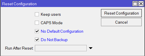
MikroTik newsletter
To follow the latest product and software news, make sure to read our newsletters in the blog section.