Introduction
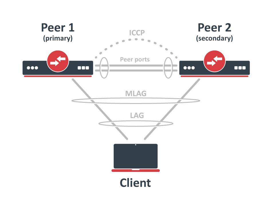
MLAG (Multi-chassis Link Aggregation Group) implementation in RouterOS allows configuring LACP bonds on two separate devices, while the client device believes to be connected to the same machine. This provides a physical redundancy in case of switch failure.
Both peers establish the MLAG interfaces and update the bridge host table over mlag-peer-port using ICCP (Inter Chassis Control Protocol). RouterOS ICCP does not require an IP configuration, it sends untagged Layer2 packets marked with EtherType 0x88B5 and a destination MAC address of 01:80:C2:00:00:0E. ICCP packets are link-local, meaning they are always received and handled by the MLAG devices themselves and never forwarded to other parts of the network. The peer-ports on each MLAG device must be directly connected to each other. It is also recommended to keep the untagged VLAN used by the peer ports separate from the rest of your network, either by assigning a dedicated untagged VLAN (using pvid), or by setting the peer port to only allow VLAN tagged frames (using frame-types=admit-only-vlan-tagged). Peer ports can be configured as single Ethernet interfaces or bonding interfaces. However, using a bonding interface is recommended, as it helps prevent a single interface failure from affecting connectivity, especially when both MLAG nodes are still up and running.
When mlag-peer-port is running and ICCP is established, the primary device election happens and system-id will be selected. The peer with the lowest priority will act as the primary device. If the priorities are the same, the peer with the lowest bridge MAC address will become the primary. This system-id is used for STP BPDU bridge identifier and LACP system ID. The MLAG supports STP, RSTP or MSTP protocols. Use the same STP priority and the same STP configuration on dual-connected bridge ports on both nodes. When MLAG bridges are elected as STP root, then both devices will show as root bridges under the bridge monitor.
Starting with RouterOS version 7.22, MLAG is configured per bridge interface instead of a dedicated MLAG submenu. Because of this change any RouterOS device (including virtual CHR instances) can be used as an MLAG node.
Hardware offloaded MLAG is only available on MikroTik devices with Marvell Prestera switch. All other devices support MLAG only in software.
What changed in the configuration syntax and monitor properties?
| RouterOS 7.22+ (new) | RouterOS 7.21- (old) |
|---|---|
Configuration menu: /interface/bridge | Configuration menu: /interface/bridge/mlag |
mlag-heartbeat | heartbeat |
mlag-peer-port | peer-port |
mlag-priority | priority |
mlag-state | status |
mlag-active-role | active-role |
bridge-id | system-id |
In other words, the mlag- prefix has been added and the whole MLAG configuration and monitor is now done under the normal bridge tree.
Upgrading to RouterOS 7.22 (or any newer release) automatically converts the old MLAG configuration to the new format, no manual changes are required.
Downgrading to a version older than 7.22 will erase the MLAG configuration, because the older firmware does not recognize the new syntax. Recommendation: before downgrading, back up the current configuration or export the MLAG settings so they can be re‑applied after the downgrade.
The MLAG is not compatible with L3 hardware offloading. When using MLAG, the L3 hardware offloading must be disabled.
The MLAG is not compatible with Multiple VLAN Registration protocol (MVRP). Registered VLANs on dual-connected bonds does not get synchronized to other MLAG node.
MLAG host synchronization can be CPU and memory intensive in networks with many hosts and VLANs. For switches with single core MIPSBE CPU (for example, CRS326-24S+2Q+RM, CRS354-48P-4S+2Q+RM, CRS518-16XS-2XQ-RM), it is recommended to use MLAG only in networks with up to 1,000 hosts.
In networks with a larger number of hosts, MLAG on these switches may lead to unexpected behavior.
Packet forwarding and load balancing
The BUM (broadcast, unknown unicast, multicast) packet forwarding happens in two stages.
Stage 1 - local forwarding:
When a node receives BUM traffic, it floods the packet locally to all ports that are members of the same VLAN - just like in a traditional (non-MLAG) setup. Additionally, it forwards the traffic over the peer-port to the other MLAG node.
Forwarding over peer-port only happens if the peer-port is also a member of the VLAN. This is why documentation emphasizes that the peer-port should be included in all VLANs that span both MLAG nodes.
Stage 2 - remote forwarding by peer:
When the peer node receives the BUM traffic over the peer-port, it floods the traffic to all regular bridge ports that are members of the same VLAN. These are ports that do not have an mlag-id specified (i.e., standalone Ethernet or bond interfaces). For mlag-id bond interfaces, the peer node makes a decision based on link status:
- If both links (local and remote) are active, it does not flood the traffic to its own MLAG bond port - this avoids sending duplicate packets since the first node has already handled that.
- If the remote peer’s link is inactive, and the local is active, the peer node will flood the traffic to the MLAG bond to ensure delivery.
The unicast traffic behaves similarly, but there is one key difference when comparing regular LAG with MLAG. In regular LAG setup, outgoing packets are load-balanced across all active links based on the transmit hash policy. In MLAG setups with both links active, traffic is not load-balanced across the peer-port between the two switches. Instead, traffic is forwarded only through the local member links of the MLAG - it always takes the shortest path. The peer-port is used only if the local MLAG link fails. In that case, traffic is forwarded to the other node via the peer-port to reach the destination. When this happens, the host table also updates the MAC address entries learned on MLAG bonds to indicate that the destination is now reachable via the peer-port. In setups where MLAG bonds consist of 2 + 2 active links (2 links per node), the transmit hashing is performed only among the two local links - not across all four links. Load balancing can be achieved when MLAG pair is used for multiple dual-connected bonds and the incoming traffic is already distributed across both pairs.
Quick setup
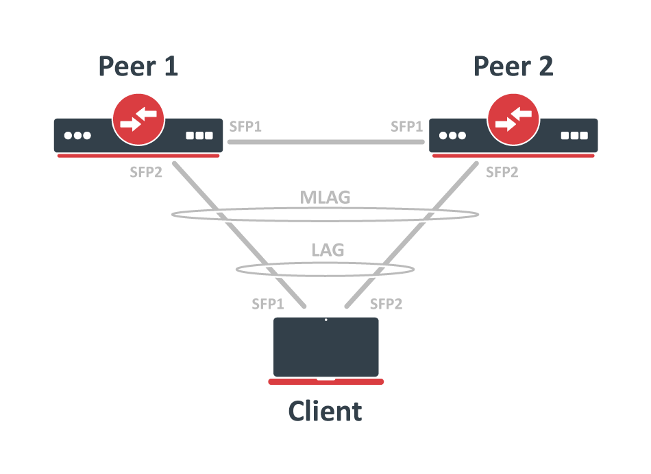
in this example, CRS317 and CRS309 devices are used as MLAG peers and any device with two SFP+ interfaces can be used as an LACP client. The SFP+1 interface is used on both peer nodes to create mlag-peer-port, and it is used for ICCP, see a network scheme below.
 Configure bonding interfaces for MLAG on Peer1 and Peer2 devices, use a matching
 mlag-id setting on both peer devices, and set the 1-second LACPDU transmission rate:
# Peer1
/interface bonding
add mlag-id=10 mode=802.3ad name=client-bond slaves=sfp-sfpplus2 lacp-rate=1sec

# Peer2
/interface bonding
add mlag-id=10 mode=802.3ad name=client-bond slaves=sfp-sfpplus2 lacp-rate=1sec
Set up the bridge interface with vlan-filtering enabled. Specify mlag-peer-port to enable MLAG. To control which device becomes the primary MLAG node, set a lower mlag-priority value on the preferred device. In this example, we want Peer1 to be the primary, so we set its priority=50. Peer2 keeps the default priority of 128, making it the secondary.
In this example, we want both MLAG nodes to act as the root bridge, so we assign a better (lower) bridge priority using priority=0x1000. Make sure both MLAG nodes use the same priority value.
Optionally, you can set frame-types=admit-only-vlan-tagged on the bridge interface to disables the default untagged VLAN 1 (pvid=1).
# Peer1
/interface bridge
add name=bridge1 vlan-filtering=yes mlag-peer-port=sfp-sfpplus1 mlag-priority=50 priority=0x1000 frame-types=admit-only-vlan-tagged

# Peer2
/interface bridge
add name=bridge1 vlan-filtering=yes mlag-peer-port=sfp-sfpplus1 priority=0x1000 frame-types=admit-only-vlan-tagged
Next, add the necessary interfaces to the bridge. In this example, only the peer port (sfp-sfpplus1) and the client-bond interface need to be added.
For the peer port, we disable the default untagged VLAN 1 (pvid=1) by configuring it to accept only VLAN-tagged traffic (frame-types=admit-only-vlan-tagged).
For the client-bond interface, we want untagged traffic to belong to VLAN 10, so we set pvid=10 on that interface.
# Peer1
/interface bridge port
add bridge=bridge1 interface=sfp-sfpplus1 frame-types=admit-only-vlan-tagged
add bridge=bridge1 interface=client-bond pvid=10

# Peer2
/interface bridge port
add bridge=bridge1 interface=sfp-sfpplus1 frame-types=admit-only-vlan-tagged
add bridge=bridge1 interface=client-bond pvid=10
The MLAG supports STP, RSTP or MSTP protocol. Use the same STP priority and the same STP configuration (e.g. path-cost, priority, edge) on dual-connected bridge ports on both nodes.
If the dual-connected bond interface is not connected to any other RSTP/MSTP bridges or switches, you can set edge=yes on that interface on both MLAG nodes.
This setting allows the bond port to quickly enter the forwarding state, which helps reduce packet loss when one side of the MLAG becomes available again.
In this example, client-bond interfaces uses VLAN 10 for untagged traffic (set with pvid=10), and we also want to allow tagged VLAN 20. To make sure traffic for both VLANs can pass between the MLAG devices, we need to add the peer ports as tagged members of VLANs 10 and 20 on both MLAG nodes. It is important to include the peer ports in all VLANs that are used on other bridge ports, this includes the untagged and tagged VLANs. Below are configuration commands for both peer devices:
# Peer1
/interface bridge vlan
add bridge=bridge1 tagged=sfp-sfpplus1 vlan-ids=10
add bridge=bridge1 tagged=sfp-sfpplus1,client-bond vlan-ids=20

# Peer2
/interface bridge vlan
add bridge=bridge1 tagged=sfp-sfpplus1 vlan-ids=10
add bridge=bridge1 tagged=sfp-sfpplus1,client-bond vlan-ids=20
All VLANs used for bridge slave ports must be also configured as tagged VLANs for peer-port, so that peer-port is a member of those VLANs and can forward data.
Last, check MLAG status on peer devices and make sure that Client LACP has both interfaces active.
# Peer1
[admin@Peer1] > /interface/bridge/monitor [find name=bridge1]
                  state: enabled
    current-mac-address: B8:69:F4:1B:B0:7C
              bridge-id: 0x1000.B8:69:F4:1B:B0:7C
            root-bridge: yes
         root-bridge-id: 0x1000.B8:69:F4:1B:B0:7C
         root-path-cost: 0
              root-port: none
             port-count: 2
  designated-port-count: 2
           fast-forward: no
             mlag-state: connected
       mlag-active-role: primary

# Peer2
[admin@Peer2] > /interface/bridge/monitor [find name=bridge1]
                  state: enabled
    current-mac-address: B8:69:F4:1B:B0:7C
              bridge-id: 0x1000.B8:69:F4:1B:B0:7C
            root-bridge: yes
         root-bridge-id: 0x1000.B8:69:F4:1B:B0:7C
         root-path-cost: 0
              root-port: none
             port-count: 2
  designated-port-count: 1
           fast-forward: no
             mlag-state: connected
       mlag-active-role: secondary

# Client
[admin@Client] > /interface bonding monitor bond1
                    mode: 802.3ad
            active-ports: sfp-sfpplus1,sfp-sfpplus2
          inactive-ports:
          lacp-system-id: 74:4D:28:7B:7F:96
    lacp-system-priority: 65535
  lacp-partner-system-id: B8:69:F4:1B:B0:7D
If the Client device is RouterOS, below is configuration command how to create a regular LACP bonding. To speed up LACP link establishment, use a 1-second LACPDU transmission rate:
/interface bonding
add mode=802.3ad name=bond1 slaves=sfp-sfpplus1,sfp-sfpplus2 lacp-rate=1sec
MLAG settings and monitoring
This section describes the available MLAG settings and monitoring options.
Sub-menu: /interface bridge
Property | Description |
|---|---|
| mlag-heartbeat (time: 1s..10s | none; Default: 00:00:05) | This setting controls how often heartbeat messages are sent to check the connection between peers. If no heartbeat message is received for three intervals in a row, the peer logs a warning about potential communication problems. If set to none, heartbeat messages are not sent at all. |
mlag-peer-port (interface | bond; Default: none) | An interface that will be used as a peer port. Both peer devices are using inter-chassis communication over these peer ports to establish MLAG and update the host table. Peer ports can be configured as single Ethernet interfaces or bonding interfaces. However, using a bonding interface is recommended, as it helps prevent a single interface failure from affecting connectivity, especially when both MLAG nodes are still up and running. It is recommended to keep the untagged VLAN used by the peer ports separate from the rest of your network, either by assigning a dedicated untagged VLAN (using All VLANs used for bridge slave ports must be also configured as tagged VLANs for peer-port (in the |
| mlag-priority (integer: 0..128; Default: 128) | This setting changes the priority for selecting the primary MLAG node. A lower number means higher priority. If both MLAG nodes have the same priority, the one with the lowest bridge MAC address will become the primary device. |
Use the /interface/bridge/monitor commands to see the current MLAG state and active role.
 [admin@Peer1] > /interface/bridge/monitor [find name=bridge1]
                  state: enabled
    current-mac-address: B8:69:F4:1B:B0:7C
              bridge-id: 0x1000.B8:69:F4:1B:B0:7C
            root-bridge: yes
         root-bridge-id: 0x1000.B8:69:F4:1B:B0:7C
         root-path-cost: 0
              root-port: none
             port-count: 2
  designated-port-count: 2
           fast-forward: no
             mlag-state: connected
       mlag-active-role: primary
Property | Description |
|---|---|
| mlag-state (connected | connecting | disabled) | The MLAG state. |
mlag-active-role (primary | secondary) | The peer with the lowest |
Sub-menu: /interface bonding
Property | Description |
|---|---|
| mlag-id (integer: 0..4294967295; Default:) | Changes MLAG ID for bonding interface. The same MLAG ID should be used on both peer devices to successfully create a single LAG for the client device. The mlag-eer-port should not be configured with the MLAG ID. |
LACP bonding interface and bonding slave ports can be monitored with monitor and monitor-slaves commands. See more details on Bonding monitoring.