Overview
Routing is the process of selecting paths across the networks to move packets from one host to another.
How Routing Works
Let's look at a basic configuration example to illustrate how routing is used to forward packets between two local networks and to the Internet.
In this setup, we have several networks:
- two client networks (192.168.2.0/24 and 192.168.1.0/24);
- one network to connect routers (172.16.1.0/30), usually called backbone;
- the last network (10.1.1.0/24) connects our gateway router (Router1) to the internet.
Router 2:
/ip address
add address=172.16.1.2/30 interface=ether1
add address=192.168.2.1/24 interface=bridge2
Router1 (gateway) where ether1 connects to the internet:
/ip address
add address=10.1.1.2/24 interface=ether1
add address=172.16.1.1/30 interface=ether2
add address=192.168.1.1/24 interface=bridge1
If we look, for example, at the Router1 routing table, we can see that the router knows only about directly connected networks. At this point, when the Client from LAN1 tries to reach the client from LAN2 (192.168.2.0/24), a packet will be dropped on the router, because the destination is unknown for the particular router:
[admin@MikroTik] > /ip/route> print
Flags: D - dynamic; X - disabled, I - inactive, A - active; C - connect, S - static, r - ri
p, b - bgp, o - ospf, d - dhcp, v - vpn
Columns: DST-ADDRESS, GATEWAY, Distance
    DST-ADDRESS    GATEWAY D
DAC 10.1.1.0/24    ether1  0
DAC 172.16.1.0/30  ether2  0
DAC 192.168.1.0/24 bridge1 0
To fix this we need to add a route that tells the router what is the next device in the network to reach the destination. In our example next hop is Router2, so we need to add a route with the gateway that points to the Router's 2 connected address. This type of route is known as a static route:
[admin@MikroTik] > /ip route add dst-address=192.168.2.0/24 gateway=172.16.1.2
[admin@MikroTik] > /ip/route> print
Flags: D - dynamic; X - disabled, I - inactive, A - active; C - connect, S - static, r - ri
p, b - bgp, o - ospf, d - dhcp, v - vpn
Columns: DST-ADDRESS, GATEWAY,       Distance
        DST-ADDRESS    GATEWAY       D
    DAC 10.1.1.0/24    ether1        0
    DAC 172.16.1.0/30  ether2        0
    DAC 192.168.1.0/24 bridge1       0
0   AS  192.168.2.0/24 172.16.1.2
At this point packet from LAN1 will be successfully forwarded to LAN2, but we are not over yet. Router2 does not know how to reach LAN1, so any packet from LAN2 will be dropped on Router2.
If we look again at the network diagram, we can clearly see that Router2 has only one point of exit. It is safe to assume that all other unknown networks should be reached over the link to Router1. The easiest way to do this is by adding a default route: To add a default route set destination 0.0.0.0/0 or leave it blank:
/ip route add gateway=172.16.1.1
As we have seen from the example setup, there are different groups of routes, based on their origin and properties.
Routing Information
RouterOS routing information consists of two main parts:
- FIB (Forwarding Information Base), is used to make packet forwarding decisions. It contains a copy of the necessary routing information.
- RIB (Routing Information Base) contains all learned prefixes from routing protocols (connected, static, BGP, RIP, OSPF).
Routing Information Base
Routing Information Base is a database that lists entries for particular network destinations and their gateways (address of the next device along the path or simply next-hop). One such entry in the routing table is called a route.
A hop occurs when a packet is passed from one network segment to another.
By default, all routes are organized in one "main" routing table. It is possible to make more than one routing table which we will discuss further in this article, but for now, for sake of simplicity, we will consider that there is only one "main" routing table.
RIB table contains complete routing information, including static routes and policy routing rules configured by the user, routing information learned from dynamic routing protocols (RIP, OSPF, BGP), and information about connected networks.
Its purpose is not just to store routes, but also to filter routing information to calculate the best route for each destination prefix, to build and update the Forwarding Information Base, and to distribute routes between different routing protocols.
Connected Routes
Connected routes represent the network on which hosts can be directly reached (direct attachment to Layer2 broadcast domain). These routes are created automatically for each IP network that has at least one enabled interface attached to it (as specified in the /ip address or /ipv6 address configuration). RIB tracks the status of connected routes but does not modify them. For each connected route there is one IP address item such that:
- address part of the dst-address of the connected route is equal to a network of IP address item.
- netmask part of dst-address of the connected route is equal to the netmask part of the address of the IP address item.
- gateway of the connected route is equal to the actual-interface of the IP address item (same as an interface, except for bridge interface ports) and represents an interface where directly connected hosts from the particular Layer3 network can be reached.
The preferred source is not used anymore for connected routes. FIB chooses the source address based on the out-interface. This allows making setups that in ROS v6 and older were considered invalid. See examples for more details.
Default Route
A default route is used when the destination cannot be resolved by any other route in the routing table. In RouterOS dst-address of the default route is 0.0.0.0/0 (for IPv4) and ::/0 (for IPv6) routes. If the routing table contains an active default route, then the routing table lookup in this table will never fail.
Typically home router routing table contains only connected networks and one default route to forward all outgoing traffic to the ISP's gateway:
[admin@TempTest] /ip/route> print
Flags: D - dynamic; X - disabled, I - inactive, A - active; C - connect, S - static, r - ri
p, b - bgp, o - ospf, d - dhcp, v - vpn
Columns: DST-ADDRESS, GATEWAY, Distance
#      DST-ADDRESS     GATEWAY      D
   DAd 0.0.0.0/0       10.155.125.1 1
   DAC 10.155.125.0/24 ether12      0
   DAC 192.168.1.0/24  vlan2        0
Hardware Offloaded Route
Devices with Layer 3 Hardware Offloading (L3HW, otherwise known as IP switching or HW routing) allow offloading packet routing onto the switch chip. When L3HW is enabled, such routes will display H-flag:
[admin@MikroTik] > /ip/route print where static
Flags: A - ACTIVE; s - STATIC, y - COPY; H - HW-OFFLOADED
Columns: DST-ADDRESS, GATEWAY, DISTANCE
#     DST-ADDRESS       GATEWAY         D
0 AsH 0.0.0.0/0         172.16.2.1      1
1 AsH 10.0.0.0/8        10.155.121.254  1
2 AsH 192.168.3.0/24    172.16.2.1      1
By default, all the routes are participating to be hardware candidate routes. To further fine-tune which traffic to offload, there is an option for each IP or IPv6 static route to disable/enable suppress-hw-offload.
For example, if we know that the majority of traffic flows to the network where servers are located, we can enable offloading only to that specific destination:
/ip route set [find where static && dst-address!="192.168.3.0/24"] suppress-hw-offload=yes
Now only the route to 192.168.3.0/24 has an H-flag, indicating that it will be the only one eligible to be selected for HW offloading:
[admin@MikroTik] > /ip/route print where static
Flags: A - ACTIVE; s - STATIC, y - COPY; H - HW-OFFLOADED
Columns: DST-ADDRESS, GATEWAY, DISTANCE
#     DST-ADDRESS       GATEWAY         D
0 As  0.0.0.0/0         172.16.2.1      1
1 As  10.0.0.0/8        10.155.121.254  1
2 AsH 192.168.3.0/24    172.16.2.1      1
H-flag does not indicate that the route is actually HW offloaded, it indicates only that route can be selected to be HW offloaded.
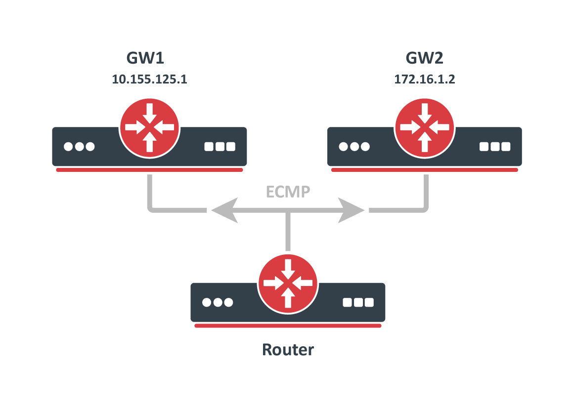
Multipath (ECMP) routes
To implement some setups, such as load balancing, it might be necessary to use more than one path to a given destination.
ECMP (Equal cost multi-path) routes have multiple gateways (next-hop) values. All reachable next-hops are copied to FIB and are used to forward packets.
These routes can be created manually, as well as dynamically by any of the dynamic routing protocols (OSPF, BGP, RIP). Multiple equally preferred routes to the same destination will have assigned + flag and grouped together automatically by RouterOS (see example below).
[admin@TempTest] /ip/route> print
Flags: D - DYNAMIC; I - INACTIVE, A - ACTIVE; C - CONNECT, S - STATIC, m - MODEM; + - ECMP
Columns: DST-ADDRESS, GATEWAY, DISTANCE
#       DST-ADDRESS      GATEWAY       D
0   AS+ 192.168.2.0/24   10.155.125.1  1
1   AS+ 192.168.2.0/24   172.16.1.2    1
By default, ECMP uses Layer3 hash policy which hashes source IP and destination IP (for IPv4) or source IP, destination IP, flow label and IP protocol (for IPv6).
It is possible to change hashing policies in /ip/setting and /ipv6/settings to Layer4 hashing or inner Layer3 hashing.
| IPv4 | IPv6 | |
|---|---|---|
| L3 | srcIPv4, dstIPv4 | srcIPv6, dstIPv6, flow label, IP proto |
| L4 | srcIPv4, dstIPv4, srcPort, dstPort, IP proto | srcIPv6, dstIPv6, srcPort, dstPort, IP Proto |
| L3-Inner |
|
|
Route Selection
There can be multiple routes with the same destination received from various routing protocols and from static configurations but only one (best) destination can be used for packet forwarding. To determine the best path, RIB runs a Route Selection algorithm that picks the best route from all candidate routes per destination.
Only routes that meet the following criteria can participate in the route selection process:
- Route is not disabled.
- If the type of route is unicast it must have at least one reachable next-hop. ( if a gateway is from a connected network and there is a connected route active, the gateway is considered as reachable)
- Route should not be synthetic.
The candidate route with the lowest distance becomes an active route. If there is more than one candidate route with the same distance, the selection of the active route is arbitrary.
Nexthop Lookup
Nexthop lookup is a part of the route selection process. Its main purpose is to find a directly reachable gateway address (next-hop). Only after a valid next-hop is selected router knows which interface to use for packet forwarding.
Nexthop lookup becomes more complicated if routes have a gateway address that is several hops away from this router (e.g. iBGP, multihop eBGP). Such routes are installed in the FIB after the next-hop selection algorithm determines the address of the directly reachable gateway (immediate next-hop).
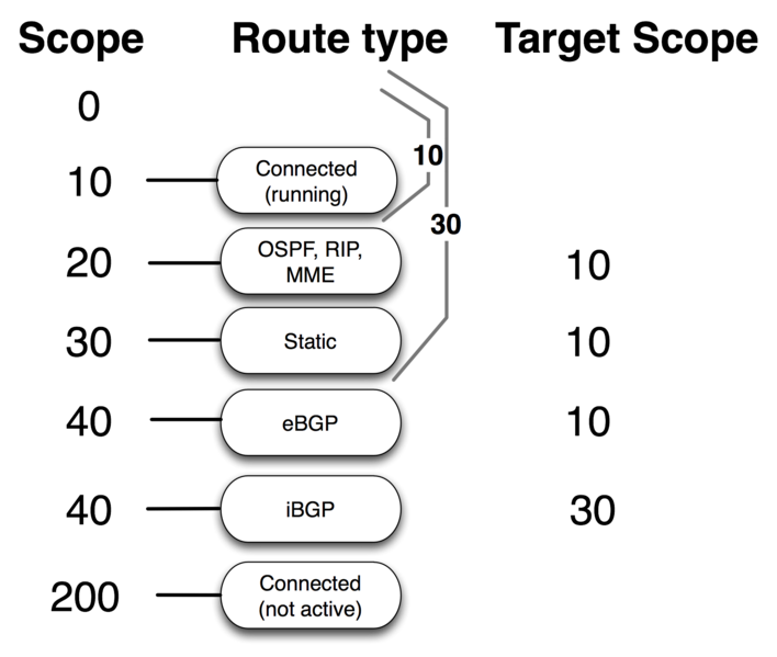
It is necessary to restrict the set of routes that can be used to look up immediate next-hops. Nexthop values of RIP or OSPF routes, for example, are supposed to be directly reachable and should be looked up only using connected routes. This is achieved using scope and target-scope properties.
Routes with a scope greater than the maximum accepted value are not used for next-hop lookup. Each route specifies the maximum accepted scope value for its nexthop in the target-scope property. The default value of this property allows nexthop lookup only through connected routes, with the exception of iBGP routes that have a larger default value and can lookup nexthop also through IGP and static routes.
Routes are processed in scope order, and updates to routes with a larger scope cannot affect the state of nexthop lookup for routes with a smaller scope.
RIB keeps multiple nexthop objects per address, one for each combination of scope and gateway check.
When target-scope or gateway check of a route is changed, it will not affect other routes, becasue these properties are internally attached to the nexthop object, not to the route.
Scope values considered as invalid and fixed automatically:
- if nexthop scope is set to 255 - RouterOS will internally fix this error by setting its scope to 254.
- if route scope is not greater than maximum accepted scope for gateway lookup - RouterOS will internally fix this error by setting nexhop scope to "target-scope + 1"
Used actual scope and target scope values can be seen in /routing/nexthop menu
Gateway check can be extended by setting check-gateway parameter. Gateway reachability can be checked by sending ARP probes, or ICMP messages or by checking active BFD sessions. The router periodically (every 10 seconds) checks the gateway by sending either an ICMP echo request (ping) or an ARP request (arp). If no response from the gateway is received for 10 seconds, the request times out. After two timeouts gateway is considered unreachable. After receiving a reply from the gateway it is considered reachable and the timeout counter is reset.
Route Storage
Routing information is stored to take as little memory as possible in a common case. These optimizations have non-obvious worst cases and impact on performance.
All routes and gateways are kept in a single hierarchy by the prefix/address.
    Dst [4]/0 1/0+4                             18  <-- number of prefixes
         ^  ^ ^ ^ ^
         |  | | | |
         |  | | | \- bytes taken by Route distinguisher or Interface Id
         |  | | \--- vrf/routing table
         |  | \----- AFI
         |  \------- netmask length of prefix
         \---------- bytes taken by prefix value

         [subject to change without notice]
Each of these 'Dst' corresponds to a unique 'dst-address' of route or address of the gateway. Each 'Dst' requires one or more 'T2Node' objects as well.
All routes with the same 'dst-address' are kept in Dst in a list sorted by route preference.
Note: WORST CASE: having a lot of routes with the same 'dst-address' is really slow! even if they are inactive! because updating a sorted list with tens of thousands of elements is slow!
Route order changes only when route attributes change. If the route becomes active/inactive, the order does not change.
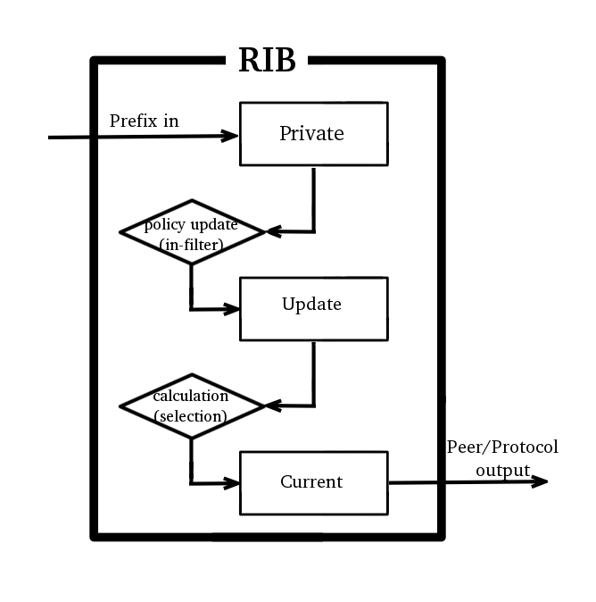
Each Route has three copies of route attributes:
- private -- what is received from the peer, before passing in-filters.
- updated -- what is the result of applying in-filters.
- current -- what are the attributes currently used by the route.
Periodically (when needed), update attributes are calculated from private attributes. This happens when route update is received, or when in-filter is updated.
When the routing table is recalculated, current attributes are set to the value from updated attributes.
This means, that usually if there is no in-filter that changes route attributes, private, updated, and current share the same value.
Route attributes are kept in several groups:
- L1 Data - all flags, list of extra properties, as-path;
- L2 Data - nexthops, RIP, OSPF, BGP metrics, route tags, originators, etc.
- L3 Data - distance, scope, kernel type, MPLS stuff
- extra properties - communities, originator, aggregator-id, cluster-list, unknown
Having for example many different combinations of distance and scope route attributes will use more memory!
Matching communities or as-path using regexp will cache the result, to speed up filtering. Each as-path or community value has a cache for all regexp, which is filled on-demand with match results.
Note: WORST CASE: changing attributes in 'in-filter' will make the route program use more memory! Because 'private' and 'updated' attributes will be different! Having a lot of different regexps will make matching slow and use a lot of memory! Because each value will have a cache with thousands of entries!
Detailed info about used memory by routing protocols can be seen in /routing stats memory menu
Forwarding Information Base
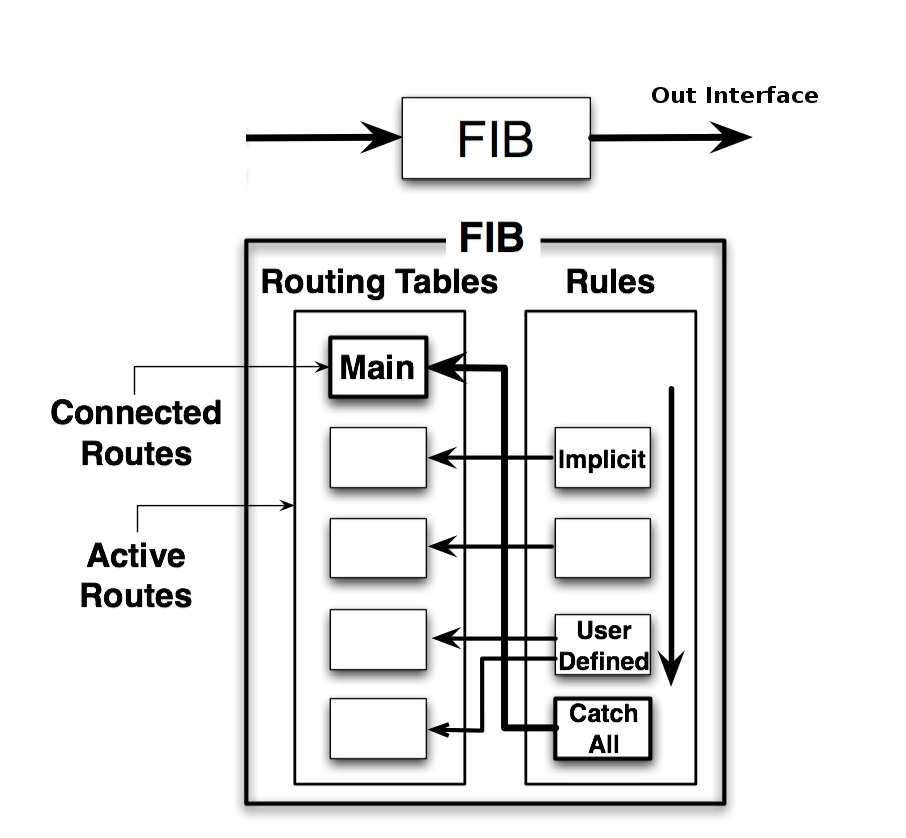
FIB (Forwarding Information Base) contains a copy of the information that is necessary for packet forwarding:
- all active routes
- policy routing rules
Each route has dst-address property, that specifies all destination addresses this route can be used for. If several routes apply to a particular IP address, the most specific one (with the largest netmask) is used. This operation (finding the most specific route that matches the given address) is called ''routing table lookup''.
Only one Best route can be used for packet forwarding. In cases where the routing table contains several routes with the same dst-address, all equally best routes are combined into one ECMP route. The best route is installed into FIB and marked as ''active''.
When forwarding decision uses additional information, such as the source address of the packet, it is called policy routing. Policy routing is implemented as a list of policy routing rules, that select different routing tables based on the destination address, source address, source interface, and routing mark (which can be changed by firewall mangle rules) of the packet.
Routing table lookup
FIB uses the following information from the packet to determine its destination:
- source address
- destination address
- source interface
- routing mark
Possible routing decisions are:
- receive packet locally
- discard the packet (either silently or by sending an ICMP message to the sender of the packet)
- send the packet to a specific IP address on a specific interface
Run routing decision:
- process policy routing rules added by a user
- check that the packet has to be resolved in a VRF other than "main", and try to resolve it, return "network unreachable" if cannot be resloved here
- check that the packet has to be locally delivered (the destination address is the address of the router from the "main" VRF)
- process implicit policy routing rules
- process implicit catch-all rule that looks up the destination in the ''main'' routing table
- the returned result is "network unreachable"
The result of the routing decision can be:
- IP address of nexthop + interface
- point-to-point interface
- local delivery
- discard
- ICMP prohibited
- ICMP host unreachable
- ICMP network unreachable
Rules that do not match the current packet are ignored. If a rule has action:
- drop or unreachable, then it is returned as a result of the routing decision process.
- lookup then the destination address of the packet is looked up in the routing table that is specified in the rule. If the lookup fails (no route matches the destination address of the packet), then FIB proceeds to the next rule.
- lookup-only is similar to lookup except that lookup fails if none of the routes in the table matches the packet.
Otherwise:
- if the type of the route is blackhole, prohibit, or unreachable, then return this action as the routing decision result;
- if this is a connected route or route with an interface as the gateway value, then return this interface and the destination address of the packet as the routing decision result;
- if this route has an IP address as the value of the gateway, then return this address and associated interface as the routing decision result;
- if this route has multiple values of nexthop, then pick one of them in a round-robin fashion.
Keep in mind that setting interface as a gateway for static routes in general is not a good idea. Interface gateway is useful only in tow scenarios:
- on point to point type interfaces
- on interfaces where dst address is directly connected,
as already stated above if interface is set as a gateway routing decision return interface and the destination address of the packet as the result, which menas that, on a broadcast network router will try to resolve packets destination address over the interface by sending ARP probes. If none of the hosts in the same broadcast domain has the IP address, forwarding will fail. So such gateways cannot be used to route packets which destination is multiple hops away.
gateway set as non point-to-point interface cannot be used to forward packets with destination multiple hops away.
Also it is not possible to use check-gateway parameter on such gateways for obvious reasons, there is no known destination IP.
Show Routes
In RouterOS you have three menus to see the current state of routes in the routing table:
/ip route- list IPv4 routes and basic properties/ipv6 route- list IPv6 routes and basic properties/routing route- list all routes with extended properties
/routing route menu currently is read-only. To add or remove routes/ip(ipv6) route menus should be used.
Example output
[admin@MikroTik] /ip/route> print
Flags: D - dynamic; X - disabled, I - inactive, A - active; C - connect, S - stati
c, r - rip, b - bgp, o - ospf, d - dhcp, v - vpn
Columns: DST-ADDRESS, GATEWAY, DIstance
#       DST-ADDRESS      GATEWAY      DI
0   XS   10.155.101.0/24  1.1.1.10
1   XS                    11.11.11.10
   D d   0.0.0.0/0        10.155.101.1 10
2   AS   0.0.0.0/0        10.155.101.1 1
3   AS + 1.1.1.0/24       10.155.101.1 10
4   AS + 1.1.1.0/24       10.155.101.2 10
5   AS   8.8.8.8          2.2.2.2      1
   DAC   10.155.101.0/24  ether12      0


|  ||| |   |                 |         |
|  ||| |   |                 |         \----Distance
|  ||| |   |                 \--Configured gateway
|  ||| |   \-- dst prefix
|  ||| \----- ECMP flag
|  ||\------- flag indicating which protocol have added the route (bgp, osf,static,connected etc.)
|  |\-------- route status flag (active, inactive, disabled)
|  \--------- shows if route is dynamic
\----------- console order number (shown only for static editable routes)
routing route output is very similar to ip route except that it shows routes from all address families in one menu and lists filtered routes as well.
[admin@MikroTik] /routing/route> print
Flags: X - disabled, I - inactive, F - filtered, U - unreachable, A - active; c - connect, s - static,
r - rip, b - bgp, o - ospf, d - dhcp, v - vpn, a - ldp-address, l - ldp-mapping
Columns: DST-ADDRESS, GATEWAY, DIStance, SCOpe, TARget-scope, IMMEDIATE-GW
     DST-ADDRESS            GATEWAY      DIS SCO TAR IMMEDIATE-GW
Xs   10.155.101.0/24
Xs
d    0.0.0.0/0              10.155.101.1 10  30  10  10.155.101.1%ether12
As   0.0.0.0/0              10.155.101.1 1   30  10  10.155.101.1%ether12
As   1.1.1.0/24             10.155.101.1 10  30  10  10.155.101.1%ether12
As   8.8.8.8                2.2.2.2      1   254 254 10.155.101.1%ether12
Ac   10.155.101.0/24        ether12      0   10      ether12
Ic   2001:db8:2::/64        ether2       0   10
Io   2001:db8:3::/64        ether12      110 20  10
Ic   fe80::%ether2/64       ether2       0   10
Ac   fe80::%ether12/64      ether12      0   10      ether12
Ac   fe80::%bridge-main/64  bridge-main  0   10      bridge-main
A    ether12                             0   250
A    bridge-main                         0   250
routing route print detail shows more advanced info useful for debugging
[admin@MikroTik] /routing route> print detail
Flags: X - disabled, I - inactive, F - filtered, U - unreachable, A - active;
c - connect, s - static, r - rip, b - bgp, o - ospf, d - dhcp, v - vpn, a - ldp-address, l - ldp-ma>
+ - ecmp
Xs dst-address=10.155.101.0/24
Xs
d afi=ip4 contribution=best-candidate dst-address=0.0.0.0/0 gateway=10.155.101.1
immediate-gw=10.155.101.1%ether12 distance=10 scope=30 target-scope=10
belongs-to="DHCP route" mpls.in-label=0 .out-label=0 debug.fwp-ptr=0x201C2000

As afi=ip4 contribution=active dst-address=0.0.0.0/0 gateway=10.155.101.1
immediate-gw=10.155.101.1%ether12 distance=1 scope=30 target-scope=10
belongs-to="Static route" mpls.in-label=0 .out-label=0 debug.fwp-ptr=0x201C2000


