Spanning Tree Protocol
The purpose of spanning tree protocol is to provide the ability to create loop-free Layer 2 topologies while having redundant links. While connecting multiple bridges or just cross-connecting bridge ports, it's possible to create network loops that can severely impact the stability of the network. Spanning tree protocol aims to resolve this problem by introducing the concept of the root bridge, all bridges in the same Layer 2 domain will exchange information about the shortest path to the root bridge. Afterward, each bridge will negotiate which ports to use to reach the root bridge. This information exchange is done with the help of Bridge Protocol Data Units (BPDUs). STP will disable certain ports for each bridge in order to avoid loops, while still ensuring that all bridges can communicate with each other. For an in-depth description of protocol please refer to 802.1Q.
As a best practice, it is always recommended to manually set up each bridge's priority, port priority, and port path cost to ensure proper Layer2 functionality at all times. Leaving STP related values to defaults are acceptable for a network that consists of 1 to 2 bridges running with (R/M)STP enabled, but it is highly recommended to manually set these values for larger networks. Since STP elects a root bridge and root ports by checking STP related values from bridges over the network, then leaving STP settings to automatic may elect an undesired root bridge and root ports and in case of a hardware failure can result in an inaccessible network.
Monitoring
You can check the STP status of a bridge by using the /interface bridge monitor command, for example:
/interface bridge monitor bridge
                  state: enabled
    current-mac-address: 64:D1:54:D9:27:E6
            root-bridge: yes
         root-bridge-id: 0x3000.64:D1:54:D9:27:E6
         root-path-cost: 0
              root-port: none
             port-count: 5
  designated-port-count: 5
Note that the root bridge doesn't have any root ports, only designated ports.
You can check the STP status of a bridge port by using the /interface bridge port monitor command, for example:
/interface bridge port monitor 2
               interface: ether3
                  status: in-bridge
             port-number: 3
                    role: root-port
               edge-port: no
     edge-port-discovery: yes
     point-to-point-port: yes
            external-fdb: no
            sending-rstp: yes
                learning: yes
              forwarding: yes
          root-path-cost: 10
       designated-bridge: 0x3000.64:D1:54:D9:27:E6
         designated-cost: 0
  designated-port-number: 4
        hw-offload-group: switch1
Note that root-bridge-id consists of the bridge priority and the bridge's MAC address, for non-root bridges the root bridge will be shown as designated-bridge. One port can have one role in an STP enabled network, below is a list of possible port roles:
- root-port - port that is facing towards the root bridge and will be used to forward traffic from/to the root bridge.
- alternate-port - port that is facing towards root bridge, but is not going to forward traffic (a backup for root port).
- backup-port - port that is facing away from the root bridge, but is not going to forward traffic (a backup for non-root port).
- designated-port - port that is facing away from the root bridge and is going to forward traffic.
- disabled-port - disabled or inactive port.
When using bridges that are set to use 802.1Q as EtherType, they will send out BPDUs to 01:80:C2:00:00:00, which are used by MSTP, RSTP, and STP. When using 802.1ad as bridge VLAN protocol, the BPDUs are not compatible with 802.1Q bridges and they are sent to 01:80:C2:00:00:08. (R/M)STP will not function properly if there are different bridge VLAN protocols across the Layer2 network.
STP and RSTP
STP and Rapid STP are used widely across many networks, but almost all networks have switched over using only RSTP since of its benefits. STP is a very old protocol and has a convergence time (the time needed to fully learn network topology changes and to continue properly forwarding traffic) of up to 50 seconds. RSTP has a lot of smaller convergence time, a few seconds or even a few milliseconds. It is recommended to use RSTP instead of STP since it is a lot faster and is also backward compatible with STP. One of the reasons why RSTP is faster is because of reduced possible port states, below is a list of possible STP port states:
- Forwarding - port participates in traffic forwarding and is learning MAC addresses, is receiving BPDUs.
- Listening - port does not participate in traffic forwarding and is not learning MAC addresses, is receiving BPDUs.
- Learning - port does not participate in traffic forwarding but is learning MAC addresses.
- Blocking - port is blocked since it is causing loops but is receiving BPDUs.
- Disabled - port is disabled or inactive.
In RSTP the disabled, listening and blocking port states are replaced with just one state called the Discarding state:
- Forwarding - port participates in traffic forwarding and is learning MAC addresses, is receiving BPDUs (forwarding=yes).
- Learning - port does not participate in traffic forwarding but is learning MAC addresses (learning=yes).
- Discarding - port does not participate in traffic forwarding and is not learning MAC addresses, is receiving BPDUs (forwarding=no).
In STP connectivity between bridges is determined by sending and receiving BPDUs between neighbor bridges. Designated ports are sending BPDUs to root ports. If a BPDU is not received 3 times the HelloTime in a row, then the connection is considered as unavailable and network topology convergence will commence. It is possible for STP to reduce the convergence time in certain scenarios by reducing the forward-delay timer, which is responsible for how long can the port be in the learning/listening state.
In RouterOS, it is possible to specify which bridge ports are edge ports. Edge ports are ports that are not supposed to receive any BPDUs, this is beneficial since this allows STP to skip the learning and the listening state and directly go to the forwarding state. This feature is sometimes called PortFast· You can leave this parameter to the default value, which is auto, but you can also manually specify it, you can set a port as edge port manually for ports that should not have any more bridges behind it, usually these are access ports.
Default values
When creating a bridge or adding a port to the bridge the following are the default values that are assigned by RouterOS:
- Default bridge priority: 32768 / 0x8000
- Default bridge port path cost: 10
- Default bridge port priority: 0x80
- BPDU message age increment: 1
- HelloTime: 2
- Default max message age: 20
RouterOS does not change port path cost based on the link speed, for 10M, 100M, 1000M, and 10000M link speeds the default path cost value when a port is added to a bridge are always 10. The age of a BPDU is determined by how many bridges have the BPDU passed times the message age since RouterOS uses 1 as the message age increment, then the BPDU packet can pass as many bridges as specified in the max-message-age parameter. By default this value is set to 20, this means that after the 20th bridge the BPDU packet will be discarded and the next bridge will become a root bridge, note that if max-message-age=20on is set, then it is hard to predict which ports will be the designated port on the 21st bridge and may result in traffic not being able to be forwarded properly.
In case bridge filter rules are used, make sure you allow packets with DST-MAC address 01:80:C2:00:00:00 since these packets carry BPDUs that are crucial for STP to work properly.
Election process
To properly configure STP in your network you need to understand the election process and which parameters are involved in which order. In RouterOS the root bridge will be elected based on the smallest priority and the smallest MAC address in this particular order:
- Bridge priority (lowest)
- Bridge MAC address (lowest)
In RouterOS root ports are elected based on lowest Root port path cost, lowest bridge identifier, and lowest bridge port ID in this particular order:
- Root port path cost (lowest)
- Bridge identifier (lowest)
- Bridge port ID (lowest)
First, when the device considers which of its ports to elect as the root port, it will check the root path cost seen by its ports. If root path cost is the same for two or more ports then the Bridge identifier of the upstream device will be checked and port connected to the lowest bridge identifier will become the root port. If the same bridge identifier is seen on two or more ports, then the Bridge port ID of the upstream device will be checked.
Explanation of attributes:
Root path cost, all bridges have a Root Path Cost. Root bridge has a root path cost of 0. For all other Bridges, it is the sum of the Port Path Costs on the least-cost path to the Root Bridge. You can modify local port path cost under "/interface bridge port".
Bridge identifier is a combination of "bridge priority" and "bridge MAC", configurable under "/interface bridge"
Bridge port ID is a combination of "unique ID" and "bridge port priority", the unique ID is automatically assigned to bridge port upon adding it to the bridge, it cannot be edited. It can be seen in WinBox under "Bridge Port" "Port Number" column, or with "/interface bridge port monitor", as "port-number".
Make sure you are using path cost and priority on the right ports. For example, setting path cost on ports that are in a root bridge has no effect, only port priority has an effect on them. Root path cost has an effect on ports that are facing towards the root bridge and port priority has an effect on ports that are facing away from the root bridge. And bridge identifier doesn’t impact the device's own root port election, instead, it affects the root port election for downstream devices.
In RouterOS it is possible to set any value for bridge priority between 0 and 65535, the IEEE 802.1W standard states that the bridge priority must be in steps of 4096. This can cause incompatibility issues between devices that do not support such values. To avoid incompatibility issues, it is recommended to use only these priorities: 0, 4096, 8192, 12288, 16384, 20480, 24576, 28672, 32768, 36864, 40960, 45056, 49152, 53248, 57344, 61440.
Examples
Root path cost example
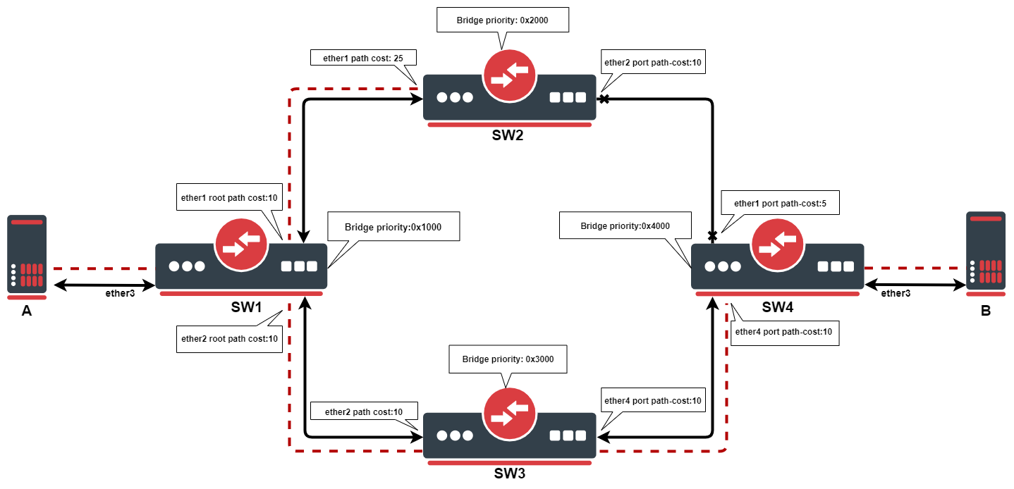
This example outlines how the root path cost works. SW1 will be the root bridge, due to it having the lowest priority of 0x1000, as the root bridge. Each bridge will calculate the path cost to the root bridge. When calculating root path cost bridges take into account configured path cost on their ports + root path cost advertised by neighboring bridges.
SW1: due to it being the root bridge, it advertises root path cost of 0 to its neighbors, even though it has a configured path cost of 10.
SW2: ether1. has root path cost of 0 + 25=25. On the ether2 path cost will be 10+10+10+0=30
SW3: ether2, has root path cost of 0 + 25=25. On the ether4 path cost will be 10+5+25+0=40
SW4: ether1, has root path cost of 0+25+5=30. On ether4 path cost will be 10+10+0=20
Port with the lowest path cost will be elected as the root port. Every bridge in STP topology needs a path to root bridge, after the best path has been found, the redundant path will be blocked, in this case, path between SW2 and SW4.
You can configure path cost on the root bridge, but it will only be taken into account when the bridge loses its root status.
STP enabled network example
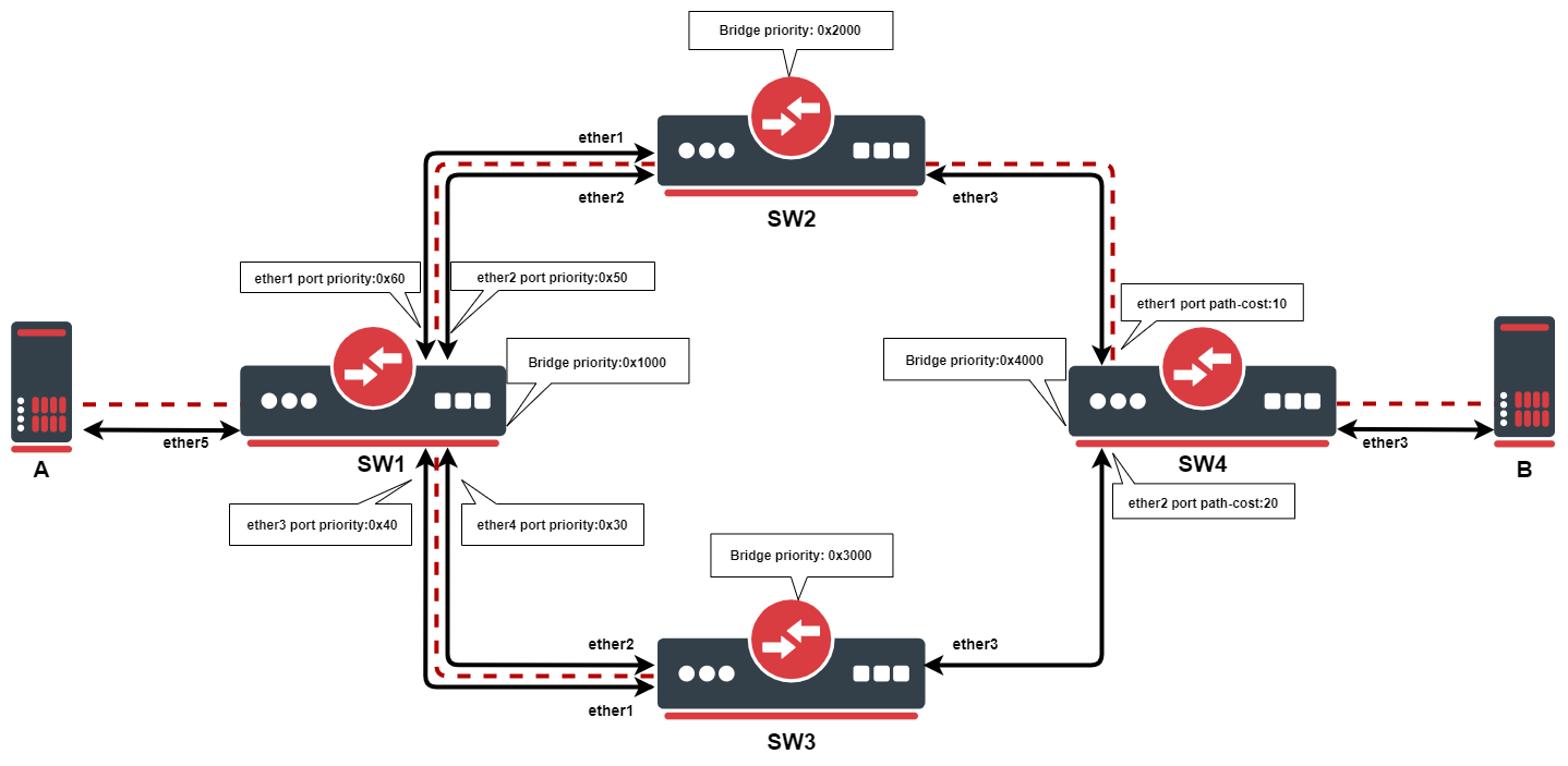
In this example, we want to ensure Layer2 redundancy for connections from ServerA to ServerB. If a port is connected to a device that is not a bridge and not running (R)STP, then this port is considered as an edge port, in this case ServerA and ServerB is connected to an edge port. This is possible by using STP in a network. Below are configuration examples for each switch.
- Configuration for SW1:
/interface bridge
add name=bridge priority=0x1000
/interface bridge port
add bridge=bridge interface=ether1 priority=0x60
add bridge=bridge interface=ether2 priority=0x50
add bridge=bridge interface=ether3 priority=0x40
add bridge=bridge interface=ether4 priority=0x30
add bridge=bridge interface=ether5
- Configuration for SW2:
/interface bridge
add name=bridge priority=0x2000
/interface bridge port
add bridge=bridge interface=ether1
add bridge=bridge interface=ether2
add bridge=bridge interface=ether3
- Configuration for SW3:
/interface bridge
add name=bridge priority=0x3000
/interface bridge port
add bridge=bridge interface=ether1
add bridge=bridge interface=ether2
add bridge=bridge interface=ether3
- Configuration for SW4:
/interface bridge
add name=bridge priority=0x4000
/interface bridge port
add bridge=bridge interface=ether1
add bridge=bridge interface=ether2 path-cost=20
add bridge=bridge interface=ether3
In this example, SW1 is the root bridge since it has the lowest bridge priority. SW2 and SW3 have ether1,ether2 connected to the root bridge and ether3 is connected to SW4. When all switches are working properly, the traffic will be flowing from ServerA through SW1_ether2, through SW2, through SW4 to ServerB. In the case of SW1 failure, the SW2 becomes the root bridge because of the next lowest priority, indicated by the dotted line in the diagram. Below is a list of ports and their role for each switch:
- root-port - SW2_ether2, SW3_ether2, SW4_ether1
- alternate-port - SW2_ether1, SW3_ether1, SW4_ether2
- designated-port - SW1_ether1, SW1_ether2, SW1_ether3, SW1_ether4, SW1_ether5, SW2_ether3, SW2_ether3, SW4_ether3
Note: By the 802.1Q recommendations, you should use bridge priorities in steps of 4096. To set a recommended priority it is more convenient to use hexadecimal notation, for example, 0 is 0x0000, 4096 is 0x1000, 8192 is 0x2000 and so on (0..F).
Multiple Spanning Tree Protocol
Multiple Spanning Tree Protocol (MSTP) is used on a bridge interface to ensure loop-free topology across multiple VLANs, MSTP can also provide Layer2 redundancy and can be used as a load balancing technique for VLANs since it has the ability to have different paths across different VLANs. MSTP is operating very similarly to (R)STP and many concepts from (R)STP can be applied to MSTP and it is highly recommended to understand the principles behind (R)STP before using MSTP, but there are some differences that must be taken into account when designing an MSTP enabled network.
In case (R)STP is used, the BPDUs are sent across all physical interfaces in a bridge to determine loops and stop ports from being able to forward traffic if it causes a loop. In case there is a loop inside a certain VLAN, (R)STP might not be able to detect it. Some STP variants solve this problem by running an STP instance on every single VLAN (PVST), but this has been proven to be inefficient and some STP variants solve this problem by running a single STP instance across all VLANs (CST), but it lacks the possibility to do load balancing for each VLAN or VLAN group. MSTP tends to solve both problems by using MST instances that can define a group of VLANs (VLAN mapping) that can be used for load balancing and redundancy, this means that each VLAN group can have a different root bridge and a different path. Note that it is beneficial to group multiple VLANs in a single instance to reduce the amount of CPU cycles for each network topology change.
In RouterOS with MSTP enabled the bridge priority is the CIST's root bridge priority, as stated in the IEEE 802.1Q standard the bridge priority must be in steps of 4096, the 12 lowest bits are ignored. These are valid bridge priorities: 0, 4096, 8192, 12288, 16384, 20480, 24576, 28672, 32768, 36864, 40960, 45056, 49152, 53248, 57344, 61440. When setting an invalid bridge priority, RouterOS will warn you about it and trunk the value to a valid value, but will save the original value in the configuration since invalid bridge priority values can still be used in (R)STP between devices running RouterOS, though it is recommended to use valid a bridge priority instead.
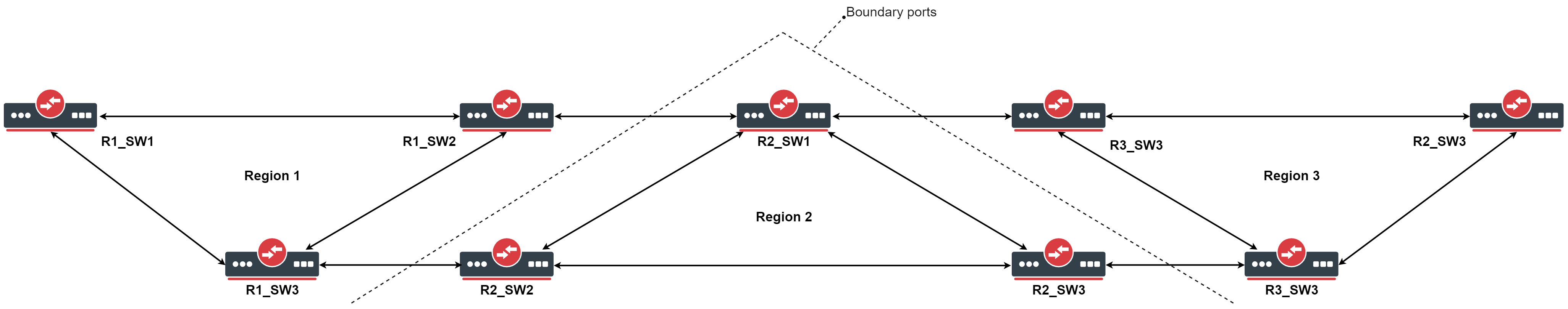
MSTP Regions
MSTP works in groups called regions, for each region there will be a regional root bridge and between regions, there will be a root bridge elected. MSTP will use Internal Spanning Tree (IST) to build the network topology inside a region and Common Spanning Tree (CST) outside a region to build the network topology between multiple regions, MSTP combines these two protocols into Common and Internal Spanning Tree (CIST), which holds information about topology inside a region and between regions. From CST's perspective, a region will seemingly be as a single virtual bridge, because of this MSTP is considered very scalable for large networks. In order for bridges to be in the same region, their configuration must match, BPDUs will not include VLAN mappings since they can be large, rather a computed hash is being transmitted. If a bridge receives a BPDU through a port and the configuration does not match, then MSTP will consider that port as a boundary port and that it can be used to reach other regions. Below is a list of parameters that need to match in order for MSTP to consider a BPDU from the same region:
- Region name
- Region revision
- VLAN mappings to MST Instance IDs (computed hash)
It is possible to create MSTP enabled network without regions, though to be able to do load balancing per VLAN group it is required for a bridge to receive a BPDU from a bridge that is connected to it with the same parameters mentioned above. In RouterOS the default region name is empty and region revision is 0, which are valid values, but you must make sure that they match in order to get multiple bridges in a single MSTP region. A region cannot exist if their bridges are scattered over the network, these bridges must be connected at least in one way, in which they can send and receive BPDUs without leaving the region, for example, if a bridge with different region related parameters is between two bridges that have the same region related parameters, then there will exist at least 3 different MSTP regions.
The downside of running every single bridge in a single MSTP region is the excess CPU cycles. In comparison, PVST(+) creates a Spanning Tree Instance for each VLAN ID that exists on the network, since there will be very limited paths that can exist in a network, then this approach creates a lot of overhead and unnecessary CPU cycles, this also means that this approach does not scale very well and can overload switches with not very powerful CPUs. MSTP solves this problem by dividing the network into MSTP regions, where each bridge inside this region will exchange and process information about VLANs that exist inside the same region, but will run a single instance of Spanning Tree Protocol in the background to maintain the network topology between regions. This approach has been proven to be much more effective and much more scalable, this means that regions should be used for larger networks to reduce CPU cycles.
In regions, you can define MST Instances, which are used to configure load balancing per VLAN group and to elect the regional root bridge. It is worth mentioning that in each region there exists a pre-defined MST Instance, in most documentations, this is called as MSTI0· This MST Instance is considered as the default MST Instance, there are certain parameters that apply to this special MST Instance. When traffic is passing through an MSTP enabled bridge, MSTP will look for an MST Instance that has a matching VLAN mapping, but if a VLAN mapping does not exist for a certain VLAN ID, then traffic will fall under MSTI0.
Since MSTP requires VLAN filtering on the bridge interface to be enabled, then make sure that you have allowed all required VLAN IDs in /interface bridge vlan, otherwise, the traffic will not be forwarded and it might seem as MSTP misconfigured, although this is a VLAN filtering misconfiguration.
Election process
The election process in MSTP can be divided into two sections, intra-region and inter-region. For MSTP to work properly there will always need to be a regional root, that is the root bridge inside a region, and a CIST root, that is the root bridge between regions. A regional root is the root bridge inside a region, regional root bridge will be needed to properly set up load balancing for VLAN groups inside a region. CIST root will be used to configure which ports will be alternate/backups ports (inactive) and which ports will be root ports (active).
Between regions, there is no load balancing per VLAN group, root port election process and port blocking between MSTP regions is done the same way as in (R)STP. If CIST has blocked a port that is inside an MSTP region to prevent traffic loops between MSTP regions, then this port can still be active for IST to do load balancing per VLAN group inside an MSTP region.
- The following parameters are involved to elect a regional root bridge or root ports inside a MSTP region:
| Property | Description |
|---|---|
| priority (integer: 0..65535 decimal format or 0x0000-0xffff hex format; Default: 32768 / 0x8000) | /interface bridge msti, MST Instance priority, used to elect a regional root inside a MSTP region. |
| internal-path-cost (integer: 1..200000000; Default: 10) | /interface bridge port, path cost to the regional root for unknown VLAN IDs (MSTI0), used on a root port inside a MSTP region. |
| priority (integer: 0..240; Default: 128) | /interface bridge port mst-override, MST port priority for a defined MST Instance, used on a bridge port on the regional root bridge. |
| internal-path-cost (integer: 1..200000000; Default: 10) | /interface bridge port mst-override, MST port path cost for a defined MST Instance, used on a non-root bridge port inside a MSTP region. |
- The following parameters are involved to elect a CIST root bridge or CIST root ports:
| Property | Description |
|---|---|
| priority (integer: 0..65535 decimal format or 0x0000-0xffff hex format; Default: 32768 / 0x8000) | /interface bridge, CIST bridge priority, used to elect a CIST root bridge. |
| priority (integer: 0..240; Default: 128) | /interface bridge port, CIST port priority, used on a CIST root bridge to elect CIST root ports. |
| path-cost (integer: 1..200000000; Default: 10) | /interface bridge port, CIST port path cost, used on a CIST non-root bridge port to elect CIST root ports. |
The sequence of parameters in which MSTP checks to elect root bridge/ports are the same as in (R)STP, you can read more about it at the (R)STP Election Process section.
MST Instance
Sub-menu: /interface bridge msti
This section is used to group multiple VLAN IDs to a single instance to create a different root bridge for each VLAN group inside an MSTP region.
| Property | Description |
|---|---|
| bridge (text; Default: ) | Bridge to which assign an MST instance. |
| identifier (integer: 1..31; Default: ) | MST instance identifier. |
| priority (integer: 0..65535 decimal format or 0x0000-0xffff hex format; Default: 32768 / 0x8000) | MST instance priority, used to determine the root bridge for a group of VLANs in an MSTP region. |
| vlan-mapping (integer: 1..4094; Default: ) | The list of VLAN IDs to assign to MST instance. This setting accepts the VLAN ID range, as well as comma, separated values. E.g. vlan-mapping=100-115,120,122,128-130 |
MST Override
Sub-menu: /interface bridge port mst-override
This section is used to select the desired path for each VLAN mapping inside an MSTP region.
| Property | Description |
|---|---|
| disabled (yes | no; Default: no) | Whether entry is disabled. |
| internal-path-cost (integer: 1..200000000; Default: 10) | Path cost for an MST instance's VLAN mapping, used on VLANs that are facing towards the root bridge to manipulate path selection, lower path cost is preferred. |
| identifier (integer: 1..31; Default: ) | MST instance identifier. |
| priority (integer: 0..240; Default: 128) | The priority an MST instance's VLAN, used on VLANs that are facing away from the root bridge to manipulate path selection, lower priority is preferred. |
| interface (name; Default: ) | Name of the port on which use configured MST instance's VLAN mappings and defined path cost and priority. |
Monitoring
Similarly to (R)STP, it is also possible to monitor MSTP status. By monitoring the bridge interface itself it possible to see the current CIST root bridge and the current regional root bridge for MSTI0, it is also possible to see the computed hash of MST Instance identifiers and VLAN mappings, this is useful when making sure that certain bridges are in the same MSTP region. Below you can find an example to monitoring an MSTP bridge:
/interface bridge monitor bridge
                    state: enabled
      current-mac-address: 6C:3B:6B:7B:F0:AA
              root-bridge: no
           root-bridge-id: 0x1000.64:D1:54:24:23:72
  regional-root-bridge-id: 0x4000.6C:3B:6B:7B:F0:AA
           root-path-cost: 10
                root-port: ether4
               port-count: 5
    designated-port-count: 3
        mst-config-digest: 74edbeefdbf82cf63a70cf60e43a56f3
In MSTP it is possible to monitor the MST Instance, this is useful to determine the current regional root bridge for a certain MST Instance and VLAN group, below you can find an example to monitor an MST Instance:
/interface bridge msti monitor 1
                    state: enabled
               identifier: 2
      current-mac-address: 6C:3B:6B:7B:F0:AA
              root-bridge: no
           root-bridge-id: 0.00:00:00:00:00:00
  regional-root-bridge-id: 0x1002.6C:3B:6B:7B:F9:08
           root-path-cost: 0
                root-port: ether2
               port-count: 5
    designated-port-count: 1
It is also possible to monitor a certain MST Override entry, this is useful to determine the port role for a certain MST Instance when configuring root ports and alternate/backup ports in an MSTP region, below you can find an example to monitor an MST Override entry:
/interface bridge port mst-override monitor 1
                      port: ether3
                    status: active
                identifier: 2
                      role: alternate-port
                  learning: no
                forwarding: no
   internal-root-path-cost: 15
         designated-bridge: 0x1002.6C:3B:6B:7B:F9:08
  designated-internal-cost: 0
    designated-port-number: 130