Overview
The Serial Console and Terminal are tools, used to communicate with devices and other systems that are interconnected via serial port. The serial terminal may be used to monitor and configure many devices - including modems, network devices (including MikroTik routers), and any device that can be connected to a serial (asynchronous) port.
The Serial Console feature is for configuring direct-access configuration facilities (monitor/keyboard and serial port) that are mostly used for initial or recovery configuration.
If you do not plan to use a serial port for accessing another device or for data connection through a modem, you can configure it as a serial console. The first serial port is configured as a serial console, but you can choose to disable it to free the port for other applications. A free serial port can also be used to access other routers' (or other equipment, like switches) serial consoles from a MikroTik RouterOS router. A special null-modem cable is needed to connect two hosts (like, two PCs, or two routers; not modems). Note that a terminal emulation program (e.g., HyperTerminal on Windows or minicom on linux) is required to access the serial console from another computer. Default settings of the router's serial port are 115200 bits/s (for x86 default is 9600 bits/s), 8 data bits, 1 stop bit, no parity, hardware (RTS/CTS) flow control.
Several customers have described situations where the Serial Terminal (managing side) feature would be useful:
- on a mountaintop, where a MikroTik wireless installation sits next to equipment (including switches and Cisco routers) that can not be managed in-band (by telnet through an IP network)
- monitoring weather-reporting equipment through a serial port
- connection to a high-speed microwave modem that needed to be monitored and managed by a serial connection
With the serial-terminal feature of the MikroTik, up to 132 (and, maybe, even more) devices can be monitored and controlled.
Serial Console Connectors
A special null-modem cable should be used for connecting to the serial console from another computer.
DB9
The Serial Console cabling diagram for DB9 connectors is as follows:
| Router Side (DB9f) | Signal | Direction | Side (DB9f) |
|---|---|---|---|
| 1, 6 | CD, DSR | IN | 4 |
| 2 | RxD | IN | 3 |
| 3 | TxD | OUT | 2 |
| 4 | DTR | OUT | 1, 6 |
| 5 | GND | - | 5 |
| 7 | RTS | OUT | 8 |
| 8 | CTS | IN | 7 |
Note that the above diagram will not work if the software is configured to do hardware flow control, but the hardware does not support it (e.g., some RouterBOARD models have reduced serial port functionality). If this is the case, either turn off the hardware flow control or use a null-modem cable with loopback, which will simulate the other device's handshake signals with it's own. The diagram for such a cable is as follows:
| Router Side (DB9f) | Signal | Direction | Side (DB9f) |
|---|---|---|---|
| 1, 4, 6 | CD, DTR, DSR | LOOP | 1, 4, 6 |
| 2 | RxD | IN | 3 |
| 3 | TxD | OUT | 2 |
| 5 | GND | - | 5 |
| 7, 8 | RTS, CTS | LOOP | 7, 8 |
Note that although it is recommended to have a 5-wire cable for this connection, in many cases it is enough to have 3 wires (for unlooped signals only), leaving both loops to exist only inside the connectors. Other connection schemes exist as well.
RJ45 Type Serial Port
This type of port is used on RouterBOARD 2011, 3011, 4011, CCR1072, CCR1036 r2 and CRS series devices, sometimes called "Cisco style" serial port.
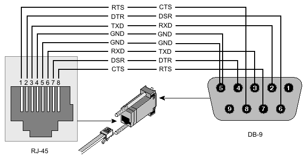
RJ45 to DB9 Cable Pinout:
| Signal | Console Port (DTE) RJ-45 | RJ-45 Rolled Cable RJ-45 Pin | Adapter DB-9 Pin | Adapter DB-25 Pin | Signal |
|---|---|---|---|---|---|
| RTS | 1 | 8 | 8 | 5 | CTS |
| DTR | 2 | 7 | 6 | 6 | DSR |
| TxD | 3 | 6 | 2 | 3 | RxD |
| Ground | 4 | 5 | 5 | 7 | Ground |
| Ground | 5 | 4 | 5 | 7 | Ground |
| RxD | 6 | 3 | 3 | 2 | TxD |
| DSR | 7 | 2 | 4 | 20 | DTR |
| CTS | 8 | 1 | 7 | 4 | RTS |
RB M33G Aditional Serial Header
For RBM33G additional serial header can be attached on GPIO pins U3_RXD, GND, U3_TXD, and 3V3
Note: RouterOS 6.45.1 and firmware are required!
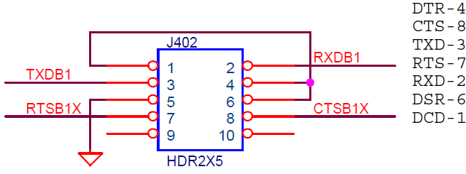
CCR Serial Header
The Cloud Core Router series devices have a serial header on the PCB board, called J402 or 100
Here is the pinout of that connector:

