...
MLAG (Multi-chassis Link Aggregation Group) implementation in RouterOS allows configuring LACP bonds on two separate devices, while the client device believes to be connected on to the same machine. This provides a physical redundancy in case of switch failure. All CRS3xx, CRS5xx series switches, and CCR2116, CCR2216 devices can be configured with MLAG using RouterOS version 7.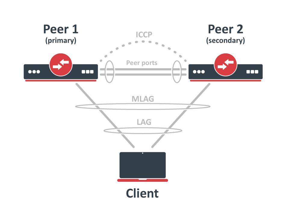
Both peers establish the MLAG interface interfaces and update the bridge host table over peer-port using ICCP (Inter Chassis Control Protocol). RouterOS ICCP does not require an IP configuration, but it should be isolated from the rest of the network traffic using a dedicated untagged VLAN. This untagged VLAN can be configured with enabled vlan-filtering and pvid. Peer ports can also be configured as LACP bonding interfaces.
When peer-port is running and ICCP is established, the primary device election happens. The peer with the lowest bridge MAC address will be acting as a primary device and system-id will be selected. This system-id is used for STP BPDU bridge identifier and LACP system ID. The MLAG requires enabled STP, RSTP or MSTP protocol. Use the same STP priority and the same STP configuration on dual-connected bridge ports on both nodes. When MLAG bridges are elected as STP root, then both devices will show as root bridges under the bridge monitor.
| Info |
|---|
The MLAG is not compatible with L3 hardware offloading. When using MLAG, the L3 hardware offloading must be disabled. |
Quick setup
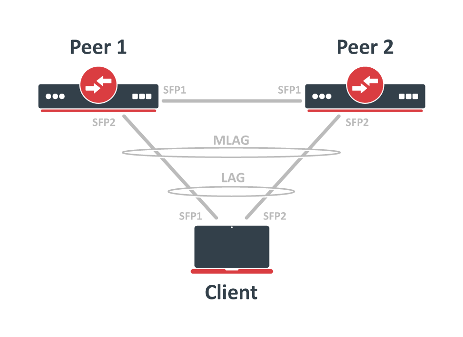
in this example, CRS317 and CRS309 devices are used as MLAG peers and any device with two SFP+ interfaces can be used as an LACP client. The SFP+1 interface is used on both peer nodes to create peer-port, and it is used for ICCP, see a network scheme below.
 Below are configuration commands to configure create a RouterOS regular LACP bonding on in RouterOS for the Client device:
| Code Block | ||
|---|---|---|
| ||
/interface bonding add mode=802.3ad name=bond1 slaves=sfp-sfpplus1,sfp-sfpplus2 |
FirstNext, configure bonding interface interfaces for MLAG on Peer1 and Peer2 devices, use a matching mlag-id setting on both peer devices:
| Code Block | ||
|---|---|---|
| ||
# Peer1 /interface bonding add mlag-id=10 mode=802.3ad name=client-bond slaves=sfp-sfpplus2 # Peer2 /interface bonding add mlag-id=10 mode=802.3ad name=client-bond slaves=sfp-sfpplus2 |
Configure Next, configure bridge with enabled vlan-filtering, and add needed interfaces as bridge ports. A dedicated untagged VLAN should be applied for the inter-chassis communication on a peer portsport, thus a different pvid setting is used. Below are configuration commands for Peer1 and Peer2 devices:
| Code Block | ||
|---|---|---|
| ||
# Peer1 /interface bridge add name=bridge1 vlan-filtering=yes /interface bridge port add bridge=bridge1 interface=sfp-sfpplus1 pvid=99 add bridge=bridge1 interface=client-bond # Peer2 /interface bridge add name=bridge1 vlan-filtering=yes /interface bridge port add bridge=bridge1 interface=sfp-sfpplus1 pvid=99 add bridge=bridge1 interface=client-bond |
| Warning |
|---|
The MLAG requires enabled STP, RSTP or MSTP protocol. Use the same STP priority and the same STP configuration on dual-connected bridge ports on both nodes. |
In this example, client-bond interfaces are using the default untagged VLAN 1 (the default pvid=1 is set). In order to send these packets over peer ports, we need to add them as tagged VLAN 1 members. Notice that the default pvid value for the peer ports was changed in the previous step, it is important to include the peer ports in all the VLANs that are used on other bridge ports, this includes the untagged and tagged VLANsAll VLANs that are allowed on MLAG ports should also be allowed on peer ports on both devices. In the previous step, peer ports were placed on a dedicated untagged VLAN, so peer ports now are added as tagged VLAN 1 member ports (the default pvid for MLAG bridge ports). Other VLANs can be added if needed. Below are configuration commands for both peer devices:
| Code Block | ||
|---|---|---|
| ||
# Peer1
/interface bridge vlan
add bridge=bridge1 tagged=sfp-sfpplus1 vlan-ids=1

# Peer2
/interface bridge vlan
add bridge=bridge1 tagged=sfp-sfpplus1 vlan-ids=1 |
| Warning |
|---|
All VLANs used for bridge slave ports must be also configured as tagged VLANs for peer-port, so that peer-port is a member of those VLANs and can forward data. |
Last, specify bridge and peer-port to enable MLAG. Below are configuration commands for both peer devices:
| Code Block | ||
|---|---|---|
| ||
# Peer1
/interface bridge mlag
set bridge=bridge1 peer-port=sfp-sfpplus1 |
Configuration options
Monitoring and troubleshooting
# Peer2
/interface bridge mlag
set bridge=bridge1 peer-port=sfp-sfpplus1 |
Additionally, check MLAG status on peer devices and make sure that Client LACP has both interfaces active.
| Code Block | ||
|---|---|---|
| ||
# Peer1
[admin@Peer1] > /interface/bridge/mlag/monitor
       status: connected
    system-id: 74:4D:28:11:70:6B
  active-role: primary

# Peer2
[admin@Peer2] > /interface/bridge/mlag/monitor
       status: connected
    system-id: 74:4D:28:11:70:6B
  active-role: secondary

# Client
[admin@Client] > /interface bonding monitor bond1
                    mode: 802.3ad
            active-ports: sfp-sfpplus1,sfp-sfpplus2
          inactive-ports:
          lacp-system-id: 74:4D:28:7B:7F:96
    lacp-system-priority: 65535
  lacp-partner-system-id: 74:4D:28:11:70:6C
|
MLAG settings and monitoring
This section describes the available MLAG settings and monitoring options.
Sub-menu: /interface bridge mlag
Property | Description |
|---|---|
| bridge (interface; Default: none) | The bridge interface where MLAG is being created. |
peer-port (interface; Default: none) | An interface that will be used as a peer port. Both peer devices are using inter-chassis communication over these peer ports to establish MLAG and update the host table. Peer port should be isolated on a different untagged VLAN using a |
Use the monitor commands to see the current MLAG status.
| Code Block | ||
|---|---|---|
| ||
[admin@Peer1] > /interface/bridge/mlag/monitor
       status: connected
    system-id: 74:4D:28:11:70:6B
active-role: primary |
Property | Description |
|---|---|
| status (connected | connecting | disabled) | The MLAG status. |
system-id (MAC address) | The lowest MAC address between both peer bridges will be used as the system-id. This system-id is used for (R)STP BPDU bridge identifier and LACP system ID. |
active-role (primary | secondary) | The peer with the lowest bridge MAC address will be acting as a primary device. The |
Sub-menu: /interface bonding
Property | Description |
|---|---|
| mlag-id (integer: 0..4294967295; Default:) | Changes MLAG ID for bonding interface. The same MLAG ID should be used on both peer devices to successfully create a single LAG for the client device. The peer-portshould not be configured with the MLAG ID. |
LACP bonding interface and bonding slave ports can be monitored with monitor and monitor-slaves commands. See more details on Bonding monitoring.
...