Chateau LTE6 (D53G-5HacD2HnD-TC&FG621-EA)
The Chateau is a home router to be used with a cellular network provider sim card.
Safety Warnings
Before you work on any equipment, be aware of the hazards involved with electrical circuitry, and be familiar with standard practices for preventing accidents.
Ultimate disposal of this product should be handled according to all national laws and regulations.
The Installation of the equipment must comply with local and national electrical codes.
This product is intended to be installed indoors. Keep this product away from water, fire, humidity, or hot environments.
Use only the power supply and accessories approved by the manufacturer, which can be found in the original packaging of this product.
Read the installation instructions before connecting the system to the power source.
We cannot guarantee that no accidents or damage will occur due to the improper use of the device. Please use this product with care and operate at your own risk!
In the case of device failure, please disconnect it from power. The fastest way to do so is by unplugging the power plug from the power outlet.
It is the customer's responsibility to follow local country regulations, including operation within legal frequency channels, output power, cabling requirements, and Dynamic Frequency Selection (DFS) requirements. All Mikrotik radio devices must be professionally installed.
Exposure to Radio Frequency Radiation: This MikroTik equipment complies with the European Union radiation exposure limits set forth for an uncontrolled environment. This MikroTik device should be installed and operated no closer than 20 centimeters from your body, occupational user, or the general public.
Quickstart
Please follow these quick steps to set up your device:
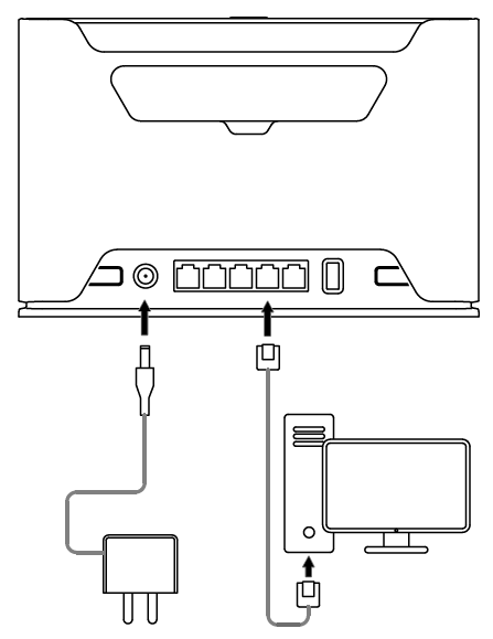
- Connect your computer to one of the Ethernet ports;
- Optional - Connect an external antenna to the SMA connector (The antennas are not provided in the package, see "Antenna usage");
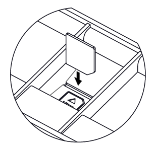
- Insert micro SIM card into the slot located under the device;
- Connect the power adapter to the DC jack;
- Once the device is powered on and the PC connected to the device, open http://192.168.88.1 in your web browser to start the configuration;
- User name: admin and there is no password by default you will be logged in automatically to the Quick Set screen (or, for some models, check user and wireless passwords on the sticker);
- We recommend clicking the "Check for updates" button on the right side and updating your RouterOS software to the latest version to ensure the best performance and stability, Must have a valid SIM card inserted;
- To manually update the device, please go to https://mikrotik.com/download

- Choose ARM packages for this device and download it to your PC.
- Upload downloaded packages to the WebFig "Files" menu and reboot the device.
- Updating your RouterOS software to the latest version will ensure the best performance, stability, and security updates.
- To personalize your wireless network, SSID can be changed in the fields "Network Name";
- Choose your country on the left side of the screen in the field "Country", to apply country regulation settings;
- Set up your wireless network password in the field "WiFi Password" the password must be at least eight symbols;
- Set up your router password in the bottom field "Password" to the right and repeat it in the field "Confirm Password", it will be used to log in next time;
- Click on the "Apply Configuration" to save changes.
Connecting with a mobile app
Use your smartphone to access your router through WiFi.

- Insert the SIM card and power on the device.
- Scan the QR code with your smartphone and choose your preferred OS.
- Connect to the wireless network. SSID starts with MikroTik and has the last digits of the device's MAC address.
- Open application.
- By default, the IP address and user name will be already entered.
- Click Connect to establish a connection to your device through a wireless network.
- Choose Quick setup and the application will guide you through all basic configuration settings in a couple of easy steps.
- An advanced menu is available to fully configure all necessary settings.
Expansion slots and ports
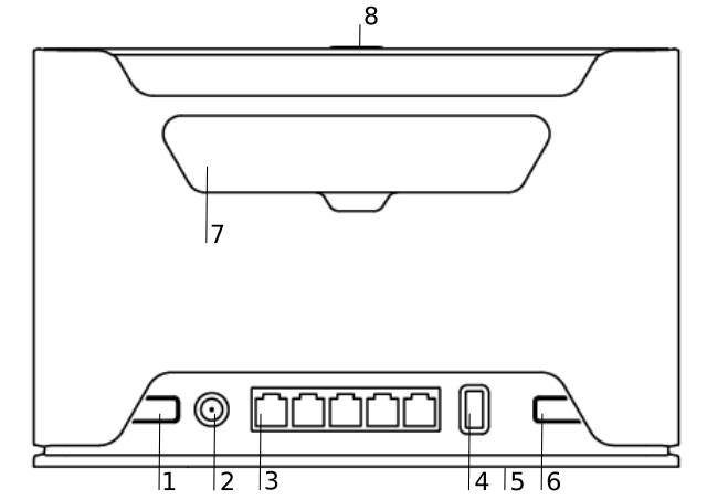
- Reset button.
- Powering DC jack 2.0 mm.
- Five Gigabit ports, supporting automatic cross/straight cable correction (Auto MDI/X). Either straight or crossover cables can be used for connecting to other network devices.
- USB type-A.
- SIM slot for Micro sim card.
- Mode button.
- Cover for external SMA antenna connectors.
- WPS Sync button.
- Integrated Wireless module operating at 2.4 GHz, 802.11b/g/n protocol.
- Integrated Wireless module operating at 5 GHz, 802.11a/n/ac protocol.
Mounting
The device is designed to be used indoors, by placing it on the desktop.
We recommend using CAT5 shielded cable. When using and installing this device please pay attention to the Maximum Permissible Exposure (MPE) safety distance with a minimum of 20 cm between the radiator and your body.
Powering
The device accepts power from an adapter:
- Direct-input power jack (5.5 mm outside and 2 mm inside, female, pin-positive plug) 12-28 V DC⎓.
The power consumption under maximum load can reach 15 W, with attachments 21 W.
Configuration
We recommend checking for updates frequently to receive the latest updates for your RouterOS software to ensure the best performance and stability.
RouterOS includes many configuration options in addition to what is described in this document. We suggest starting here to get yourself accustomed to the possibilities: https://mt.lv/help. In case IP connection is not available, the Winbox tool (https://mt.lv/winbox) can be used to connect to the MAC address of the device from the LAN side (all access is blocked from the Internet port by default).
For recovery purposes, it is possible to boot the device for reinstallation, see section Buttons and Jumpers.
Mode button
Mode button is located on the back of the unit, to the right side (see "Expansion slots and ports")
The Default configuration for the Mode button is dark mode - to turn off all LEDs. The button can be configured in RouterOS to run any user-specified scripts.
Sync button
The sync button is located on the top of the unit. The WPS Sync button, if configured on the wireless interface, can be used to connect new clients.

- Press and hold the WPS button for 1 – 5 seconds to enable WPS for wireless interfaces.
Front LED status
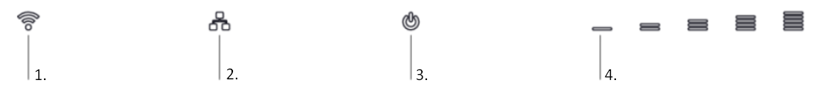
- Wireless network activity.
- Ethernet port activity.
- System LED with alternate mode for cellular modem status indication.
- Signal strength.
System LED alternate modem mode indications
When cellular modem interface is enabled, System LED have have alternate indications:
blinking red - SIM card not inserted
yellow - established connection in 3G mode
blue - established connection in LTE mode
blinking - connection establishment in progress, modem registered in cellular network, APN is not activated yet
SIM slot usage
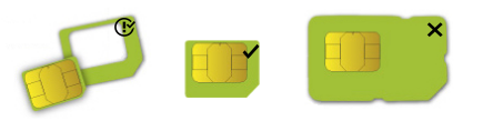
SIM card slot is designed to be used with Micro SIM cards.
Nano SIM cards have different thickness, and usage with an adapter are not recommended.
Reset button
The reset button has three functions:
- Hold this button during boot time until the green LED light starts flashing, release the button to reset RouterOS configuration (total 5 seconds).
- Keep holding for 5 more seconds, LED turns solid, release now to turn on CAP mode. The device will now look for a CAPsMAN server (total of 10 seconds).
- To reinstall RouterOS using the Netinstall utility, enter the device into BOOTP mode. There are two types of booters available: the regular booter and the backup booter.
- Regular booter - Power on the device, wait 1-2 seconds, then press and hold the Reset button. Wait until the System LED is blinking green, then turns solid "On". When the green LED turns "Off", release the Reset button - the device will enter BOOTP mode.
- Backup booter – Power off the device, press and hold the Reset button, then power it on. Wait until the System LED is blinking green, then solid "On". When the green LED turns "Off", release the Reset button - the device will enter BOOTP mode using the backup booter.
Regardless of the above option used, the system will load the backup RouterBOOT loader if the button is pressed before power is applied to the device. Useful for RouterBOOT debugging and recovery.
Netinstall
When performing Netinstall, make sure to use the latest v7 version of both ROS files and the Netinstall software.
Accessories
The package includes the following accessories that come with the device:
- EU/US Switching Power Supply 24 V ⎓, 1.2 A, 28.8 W, 86.8 %, VI, cable:150 cm.
- CAT5E UTP Flat Cable, 8P8C, AWG32, 1.5 m.
LTE Antenna usage
SMA connectors are for LTE antennas.
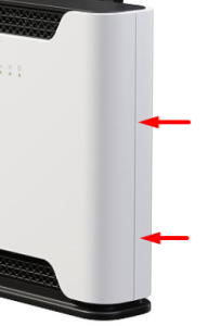
The device has two external antenna connectors on the back behind the doors.
- Open doors by pulling them upwards.
- Screw the LTE antenna to the SMA connector located on the left side. The maximum diameter for antenna connectors or any other adapters used is 13 mm.
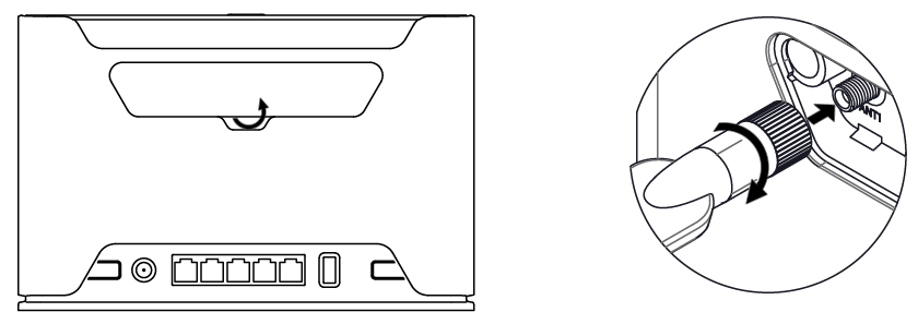
When using one antenna, please connect to the SMA connector on the left side (ANT1).
Only when using two antennas, you can connect to the right SMA connector (ANT4).

Please connect and disconnect the antenna, when the device is turned off!
SMA connectors on the device are female.
We recommend using our antenna https://mikrotik.com/product/mant_lte_5o
Removing front cover to access PCB
In case there is a need to access PCB, the front cover can be removed.
- Remove center screw;
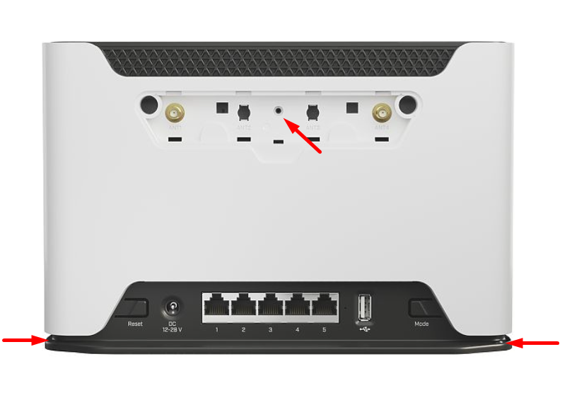
- Use a small screwdriver to pry open cover in marked spots;
- Continue to pry it open by going up;
- At the end lift off the whole cover.
Operating system support
The device supports RouterOS software version v7. The specific factory-installed version number is indicated in the RouterOS menu /system resource. Other operating systems have not been tested.
To avoid pollution of the environment, please separate the device from household waste and dispose of it in a safe manner, such as at designated waste disposal sites. Familiarize yourself with the procedures for the proper transportation of the equipment to the designated disposal sites in your area.