Summary
The GPEN21 is a smart power injector that serves as an advanced software-controlled repeater. Not only can it power your uplink devices via PoE, but it can also provide a range of useful software features. GPEN21 has an Ethernet and SFP port for fiber connectivity. Customers can choose to use GPEN21 to power optical module for uplink to the provider, or to provide PoE to power Ethernet uplink to the provider (that uses our GPeR and/or netPower products). The GPEN21 unit can be securely attached to a wall or the communications cabinet. The Ethernet cable can be routed either directly through its bottom cable opening or into the wall, as preferred.
SwOS Lite is an operating system designed specifically for the administration of MikroTik GPEN21 products. GPEN21 support only SwOS Lite operating system.
GPEN21 series features
| Features | Description |
|---|---|
| Forwarding |
|
| Monitoring |
|
| VLAN |
|
| Security |
|
| Quality of Service (QoS) |
|
| Access Control List |
|
1 The Host table limit does not affect forwarding because packets are sent from upstream to downstream ports and vice versa even when the MAC learning limit is reached.
Connecting to the Device
Open your web browser and enter the IP address of your device (192.168.88.1 by default) and a login screen will appear. The device can also run a DHCP client, see if a different IP address has been assigned by the DHCP server.
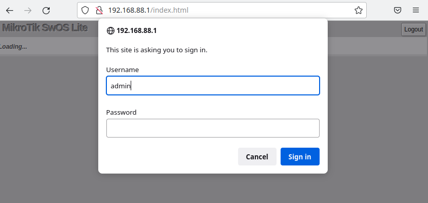
SwOS default IP address: 192.168.88.1, user name: admin and there is no password.
MikroTik Neighbor Discovery can be used to discover the IP address of the device. LLDP is not supported.
Interface Overview
SwOS interface menu consists of multiple tabs depending on the device model. These are all possible SwOS menus: Link, SFP, Forwarding, Stats, Errors, Hist, VLAN, VLANs, Hosts, SNMP, ACL, System, and Upgrade.
Description of buttons in SwOS configuration tool:
- Append - add a new item to the end of the list
- Apply All - applies current configuration changes
- Cut - removes an item from the list
- Clear - reset properties of the item
- Discard Changes - removes unsaved configuration
- Insert - add a new item to the list (places it before current item)
- Sort - sort VLAN table by VLAN-IDs; sort host table by MAC addresses
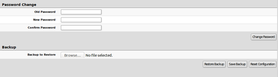
- Change Password - changes the password of the device
- Logout - logout from the current device
- Reboot - reboot the device
- Reset Configuration - reset configuration back to factory defaults
- Choose File - browse for upgrade or backup file
- Upgrade - upgrade the firmware of the device using the selected file
- Download & Upgrade - automatically try to download and upgrade the firmware, the PC which is running a web browser should be able to access the Internet
- Restore Backup - restore device using a selected backup file
- Save Backup - generate and download the backup file from the device
Each device has its own firmware which cannot be installed on other series models!
- GPEN21 supports SwOS Lite v2.13 and newer.
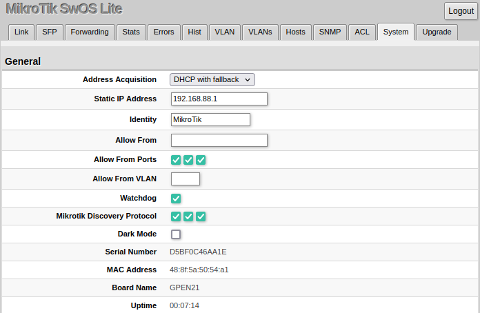
System
System Tab performs the following functions:
- General information about the device
- Device management
- Configuration reset
- Backup and restore configuration
SwOS uses a simple algorithm to ensure TCP/IP communication - it just replies to the same IP and MAC address packet came from. This way there is no need for Default Gateway on the device itself.
| Property | Description |
|---|---|
| Address Acquisition | Specify which address acquisition method to use:
|
| Static IP Address | IP address of the device in case of Address Acquisition is set as DHCP with fallback or static |
| Identity | Name of the device (for Mikrotik Neighbor Discovery protocol) |
| Allow From | IP address from which the device is accessible. Default value is '0.0.0.0/0' - any address |
| Allow From Ports | List of device ports from which it is accessible |
| Allow From VLAN | VLAN ID from which the service is accessible. Make sure to first configure VLANs and VLAN pages |
| Watchdog | Enable or disable system Watchdog. It will reset the CPU of the device in case of a fault condition |
| Mikrotik Discovery Protocol | Enable or disable Mikrotik Neighbor Discovery protocol |
| Dark Mode | Disable or enable all LEDs on the device |
| MAC Address | MAC address of the device (read-only) |
| Serial Number | Serial number of the device (read-only) |
| Board Name | MikroTik model name of the device (read-only) |
| Uptime | Current device uptime (read-only) |
| PoE Out Mode | Specifies PoE-Out state:
|
| PoE Out Status | Shows current PoE-Out status on port (read-only) |
Password and Backup
Link
Link Tab allows you to configure each interface settings and monitor the link status.
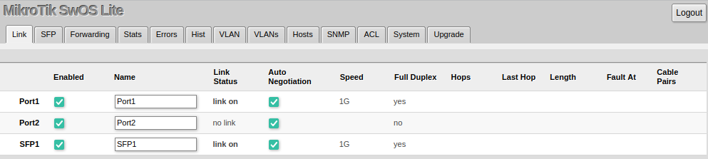
| Property | Description |
|---|---|
| Enabled | Enable or disable port |
| Name | Editable port name |
| Link Status | Current link status (read-only) |
| Auto Negotiation | Enable or disable auto-negotiation |
| Speed | Shows the negotiated speed, or allows manually changing the speed setting of the port (requires auto-negotiation to be disabled) |
| Full Duplex | Shows the negotiated duplex, or allows manually changing the duplex mode of the port (requires auto-negotiation to be disabled) |
| Hops | Shows the number of GPER repeaters in the link |
| Last Hop | Shows the number of the last GPER repeater if the link is terminated |
| Length | Shows the length of the cable in meters if the link is terminated |
| Fault At | Shows the distance in meters to the failure point if the cable is damaged but the link is active |
| Cable Pairs | Shows four positions of the cable pairs with their status: O - open; S - short; P - reverse polarity |
The device supports Jumbo frames up to 10222 bytes. Manually decreasing the MTU settings is not supported for SwOS Lite devices.
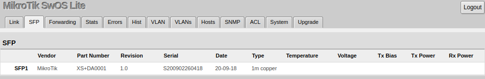
SFP
The SFP tab allows you to monitor the status of SFP modules.
Forwarding
Forwarding Tab provides advanced forwarding options among device ports, port locking, bandwidth limit, and broadcast storm control features.
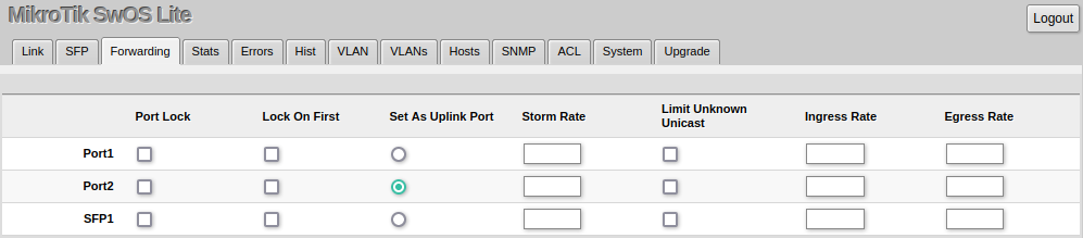
| Property | Description |
|---|---|
| Port Lock |
|
| Uplink Port |
|
| Broadcast Storm Control |
|
| Bandwidth Limit |
|
It is possible to limit ingress/egress traffic per port basis. The policer is used for ingress traffic, the shaper is used for egress traffic. The ingress policer controls the received traffic with packet drops. Everything that exceeds the defined limit will get dropped. This can affect the TCP congestion control mechanism on end hosts and achieved bandwidth can be actually less than defined. The egress shaper tries to queue packets that exceed the limit instead of dropping them. Eventually, it will also drop packets when the output queue gets full, however, it should allow utilizing the defined throughput better.
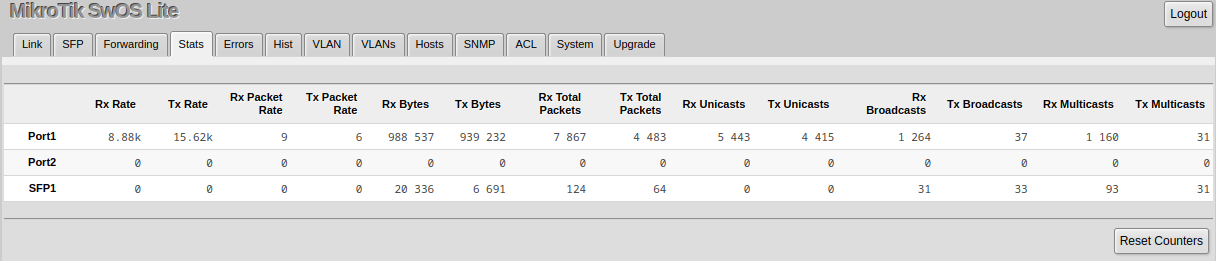
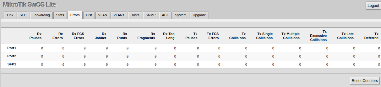
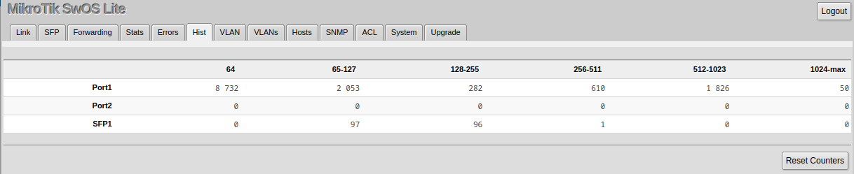
Stats, Errors and Histogram
These menus provide detailed information about received and transmitted packets.
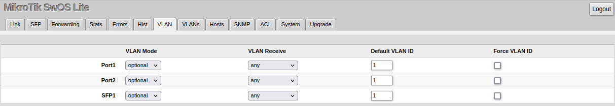
VLAN and VLANs
VLAN configuration for device ports.
| Property | Description |
|---|---|
| VLAN Mode (disabled | optional | strict; Default: optional) | VLAN filtering mode, these options are relevant to egress ports (except for strict mode).
|
| VLAN Receive (any | only tagged | only untagged; Default: optional) | Received traffic filtering based on VLAN tag presence.
|
| Default VLAN ID (integer: 1..4095; Default: 1) | The device will place received untagged packets in the "Default VLAN ID" VLAN. Only has an effect on untagged traffic, and when VLAN Receive is set to "any" or "only untagged". It does not apply for tagged traffic. This parameter is usually used to allocate access ports with specific VLAN. It is also used to untag egress traffic if the packet's VLAN ID matches Default VLAN ID. |
| Force VLAN ID (integer: yes | no; Default: no) | Assigns the Default VLAN ID value to all ingress traffic (tagged and untagged). Has effect in all VLAN Modes. If the port receives tagged traffic and Default VLAN ID is set to 1, then with this parameter the egress traffic will be untagged. |
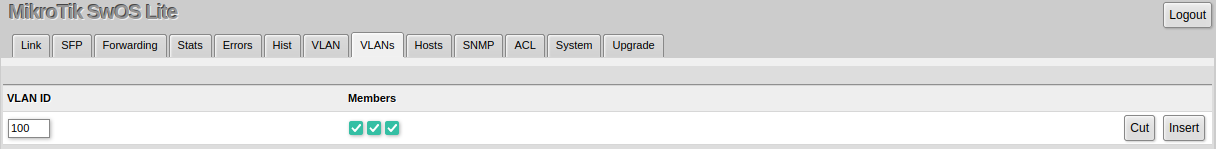
VLAN membership configuration for device ports.
| Property | Description |
|---|---|
| VLAN ID (integer: 1..4094; Default: 0) | VLAN ID to which assign ports. |
| Members (ports; Default: none) | Group of ports, which are allowed to forward traffic on the defined VLAN. |
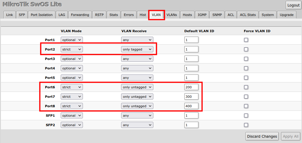
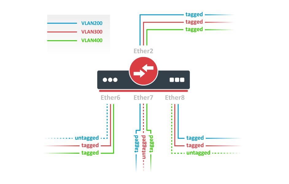
VLAN Configuration Example
The VLAN configuration examples are taken from the CSS610 switch user manual, however, the same principles can be applied to the GPEN21 device.
Trunk and Access Ports
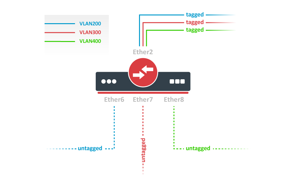
1. In the VLANs menu add VLAN entries and specify port membership.
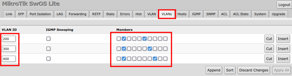 2. In the VLAN menu configure Default VLAN ID on planned access ports (untagged), select the correct VLAN Receive setting (Port2 only tagged, Port6-8 only untagged) and enable strict VLAN filtering to ensure only allowed VLANs can pass through the ports.
Trunk and Hybrid Ports
1. In the VLANs menu add VLAN entries and specify port membership.
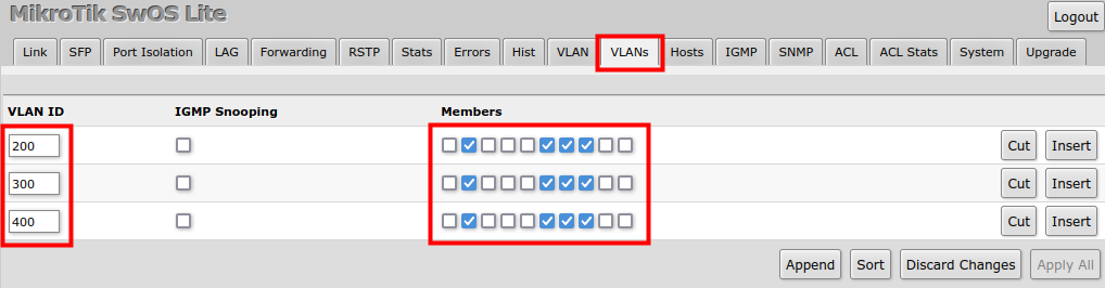 2. In the VLAN menu configure Default VLAN ID on planned hybrid ports (for untagged VLAN), select the correct VLAN Receive setting (Port2 only tagged, Port6-8 any) and enable strict VLAN filtering to ensure only allowed VLANs can pass through the ports.
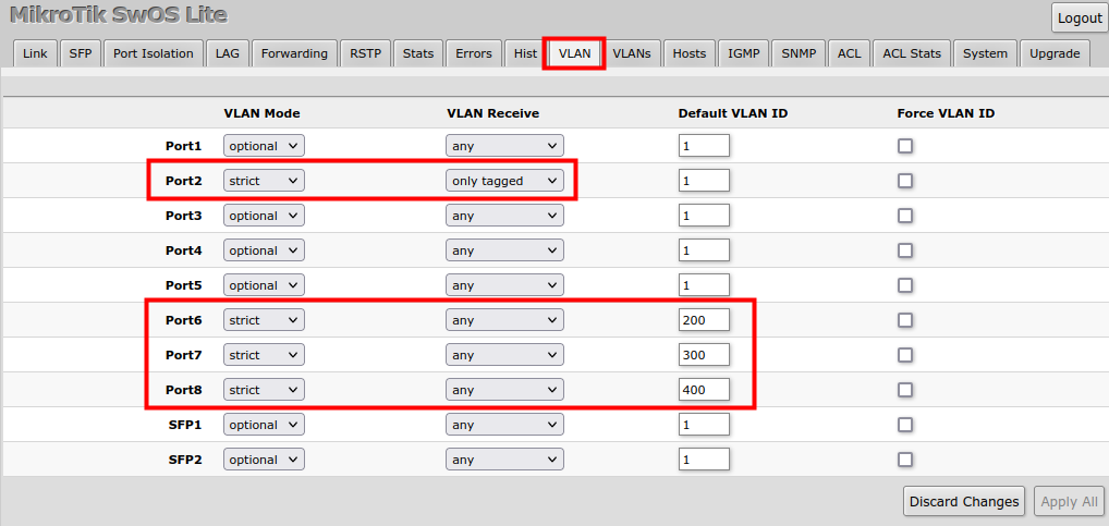
Management access
In this example, device management access on VLAN 200 will be created. The configuration scheme is the same as "Trunk and Access Ports" and 1., 2. configuration steps are identical. The additional 3rd step requires specifying the management VLAN ID in the System menu. After applying the configuration, the device will only respond to tagged VLAN 200 packets on Port2 and untagged packets on Port6. The DHCP client will also work in the specified VLAN ID.
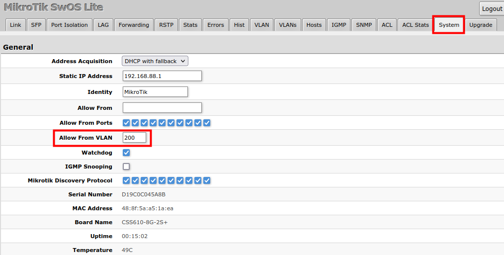
Changing management VLAN can completely disable access to the device management if VLAN settings are not correctly configured. Save a configuration backup before changing this setting and use Reset in case management access is lost.
Hosts
This table represents dynamically learned MAC address to port mapping entries. It can contain two kinds of entries: dynamic and static. Dynamic entries get added automatically, this is also called a learning process: when a device receives a packet from a certain port, it adds the packet's source MAC address and port it received the packet from to the host table, so when a packet comes in with a certain destination MAC address it knows to which port it should forward the packet. If the destination MAC address is not present in the host table then it forwards the packet to all ports in the group. Dynamic entries take about 5 minutes to time out.
Static entries will take over dynamic if dynamic entry with the same mac-address already exists. Also by adding a static entry you get access to more functionality.
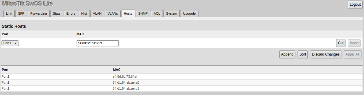
| Property | Description |
|---|---|
| Ports | Ports the packet should be forwarded to |
| MAC | MAC address |
| Port (read-only) | Ports the packet should be forwarded to |
| MAC (read-only) | Learned MAC address |
SNMP
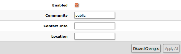
SwOS supports SNMP v1 and v2c (the Response for GetRequest, GetNextRequest and GetBulkRequest) and uses IF-MIB, SNMPv2-MIB, BRIDGE-MIB and MIKROTIK-MIB (only for health, PoE-out and SFP diagnostics). SNMP traps and writing SwOS configuration are not supported.
Available SNMP data:
- System information
- System uptime
- Port status
- Interface statistics
- Host table information
| Property | Description |
|---|---|
| Enabled | Enable or disable SNMP service |
| Community | SNMP community name |
| Contact Info | Contact information for the NMS |
| Location | Location information for the NMS |
ACL
An access control list (ACL) rule table is a very powerful tool allowing wire-speed packet filtering, forwarding, and VLAN tagging based on L2,L3, and L4 protocol header field conditions. Each rule contains a conditions part and an action part.

Conditions part parameters
| Property | Description |
|---|---|
| From | A port that packet came in from |
| MAC Src | Source MAC address and mask |
| MAC Dst | Destination MAC address and mask |
| Ethertype | Protocol encapsulated in the payload of an Ethernet Frame |
| VLAN | VLAN header presence:
|
| VLAN ID | VLAN tag ID |
| Priority | Priority in VLAN tag |
| IP Src (IP/netmask:port) | Source IPv4 address, netmask, and L4 port number |
| IP Dst (IP/netmask:port) | Destination IPv4 address, netmask, and L4 port number |
| Protocol (integer) | IP protocol |
| DSCP | IP DSCP field |
Action part parameters
| Property | Description |
|---|---|
| Drop | Drop packet |
| Set VLAN ID | Changes the VLAN tag ID, if the VLAN tag is present |
| Priority | Changes the VLAN tag priority bits, if the VLAN tag is present |
Reset and Reinstall
The GPEN21 has built-in backup SwOS firmware which can be loaded in case standard firmware breaks or an upgrade fails:
- Holding the Reset button for a few seconds while the device is booting will reset the configuration and load backup firmware. The reset button is located behind the front cover.
- After loading backup firmware, it is possible to connect to 192.168.88.1 (or leased address from a DHCP server) using a web browser and install new SwOS firmware.