Summary
This page will show how to configure multiple switches to use bonding interfaces and port-based VLANs, it will also show a working example with a DHCP-Server, inter-VLAN routing, management IP, and invalid VLAN filtering configuration.
This article applies to CRS3xx, CRS5xx, CCR2116, and CCR2216 devices. It doesn't apply to CRS1xx/CRS2xx series.
For this network topology, we will be using two CRS326-24G-2S+, one CRS317-1G-16S+, and one CCR1072-1G-8S+, but the same principles can be applied to any CRS3xx, CRS5xx series devices, and a router.
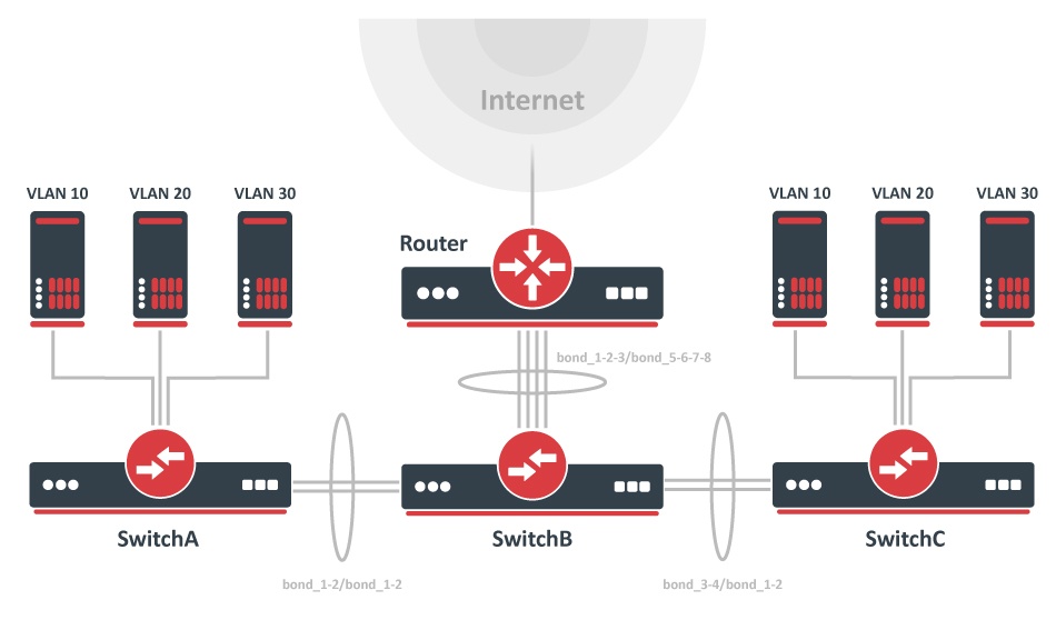
In this setup, SwitchA and SwitchC will tag all traffic from ports ether1-ether8 to VLAN ID 10, ether9-ether16 to VLAN ID 20, and ether17-ether24 to VLAN ID 30. Management will only be possible if a user is connecting with tagged traffic with VLAN ID 99 from ether1 on SwitchA or SwitchB, connecting to all devices will also be possible from the router using tagged traffic with VLAN ID 99. The SFP+ ports in this setup are going to be used as VLAN trunk ports while being in a bond to create a LAG interface.
Bonding
Bonding interfaces are used when a larger amount of bandwidth is required, this is done by creating a link aggregation group, which also provides hardware automatic failover and load balancing for switches. By adding two 10Gbps interfaces to bonding, you can increase the theoretical bandwidth limit to 20Gbps. Make sure that all bonded interfaces are linked to the same speed rates.
When using the hardware-offloaded bridge, the CRS3xx, CRS5xx, CCR2116, and CCR2216 devices aggregate traffic using the built-in switch chip without using CPU resources. To route the traffic a router with a powerful CPU is required to handle the aggregated traffic.
To create a 20Gbps bonding interface from sfp-sfpplus1 and sfp-sfpplus2 between SwitchA to SwitchB and between SwitchC to SwitchB, use these commands on SwitchA and SwitchC:
/interface bonding
add mode=802.3ad name=bond_1-2 slaves=sfp-sfpplus1,sfp-sfpplus2
To create a 40Gbps bonding interface between SwitchB and the Router and a 20Gbps bonding interface between SwitchA and SwitchC, use these commands on SwitchB:
/interface bonding
add mode=802.3ad name=bond_1-2 slaves=sfp-sfpplus1,sfp-sfpplus2
add mode=802.3ad name=bond_3-4 slaves=sfp-sfpplus3,sfp-sfpplus4
add mode=802.3ad name=bond_5-6-7-8 slaves=sfp-sfpplus5,sfp-sfpplus6,sfp-sfpplus7,sfp-sfpplus8
In our case the Router needs a software-based bonding interface, use these commands on the Router:
/interface bonding
add mode=802.3ad name=bond_1-2-3-4 slaves=sfp-sfpplus1,sfp-sfpplus2,sfp-sfpplus3,sfp-sfpplus4
Interface bonding does not create an interface with a larger link speed. Interface bonding creates a virtual interface that can load balance traffic over multiple interfaces. More details can be found on the LAG interfaces and load balancing page.
Port switching
All switches in this setup require that all used ports are switched together. For bonding, you should add the bonding interface as a bridge port, instead of individual bonding ports. Use these commands on SwitchA and SwitchC:
/interface bridge
add name=bridge vlan-filtering=no
/interface bridge port
add bridge=bridge interface=ether1 pvid=10
add bridge=bridge interface=ether2 pvid=10
add bridge=bridge interface=ether3 pvid=10
add bridge=bridge interface=ether4 pvid=10
add bridge=bridge interface=ether5 pvid=10
add bridge=bridge interface=ether6 pvid=10
add bridge=bridge interface=ether7 pvid=10
add bridge=bridge interface=ether8 pvid=10
add bridge=bridge interface=ether9 pvid=20
add bridge=bridge interface=ether10 pvid=20
add bridge=bridge interface=ether11 pvid=20
add bridge=bridge interface=ether12 pvid=20
add bridge=bridge interface=ether13 pvid=20
add bridge=bridge interface=ether14 pvid=20
add bridge=bridge interface=ether15 pvid=20
add bridge=bridge interface=ether16 pvid=20
add bridge=bridge interface=ether17 pvid=30
add bridge=bridge interface=ether18 pvid=30
add bridge=bridge interface=ether19 pvid=30
add bridge=bridge interface=ether20 pvid=30
add bridge=bridge interface=ether21 pvid=30
add bridge=bridge interface=ether22 pvid=30
add bridge=bridge interface=ether23 pvid=30
add bridge=bridge interface=ether24 pvid=30
add bridge=bridge interface=bond_1-2
Add all bonding interfaces to a single bridge on SwitchB by using these commands on SwitchB:
/interface bridge
add name=bridge vlan-filtering=no
/interface bridge port
add bridge=bridge interface=bond_1-2
add bridge=bridge interface=bond_3-4
add bridge=bridge interface=bond_5-6-7-8
Management IP
It is very useful to create a management interface and assign an IP address to it to preserve access to the switch. This is also very useful when updating your switches since such traffic to the switch will be blocked when enabling invalid VLAN filtering.
Create a routable VLAN interface on SwitchA, SwitchB, and SwitchC:
/interface vlan
add interface=bridge name=MGMT vlan-id=99
The Router needs a routable VLAN interface to be created on the bonding interface, use these commands to create a VLAN interface on the Router:
/interface vlan
add interface=bond_1-2-3-4 name=MGMT vlan-id=99
For this guide, we are going to use these addresses for each device:
| Device | Address |
|---|---|
| Router | 192.168.99.1 |
| SwitchA | 192.168.99.2 |
| SwitchB | 192.168.99.3 |
| SwitchC | 192.168.99.4 |
Add an IP address for each switch device on the VLAN interface (change X to the appropriate number):
/ip address
add address=192.168.99.X/24 interface=MGMT
Do not forget to add the default gateway and specify a DNS server on the switch devices:
/ip route
add gateway=192.168.99.1
/ip dns
set servers=192.168.99.1
Add the IP address on the Router:
/ip address
add address=192.168.99.1/24 interface=MGMT
Invalid VLAN filtering
Since most ports on SwitchA and SwitchC are going to be access ports, you can set all ports to accept only certain types of packets, in this case, we will want SwitchA and SwitchC to only accept untagged packets, use these commands on SwitchA and SwitchC:
/interface bridge port
set [ find ] frame-types=admit-only-untagged-and-priority-tagged
There is an exception for frame types on SwitchA and SwitchC, in this setup access to the management is required from ether1 and bonding interfaces, they require that tagged traffic can be forwarded. Use these commands on SwitchA and SwitchC:
/interface bridge port
set [find where interface=ether1] frame-types=admit-all
set [find where interface=bond_1-2] frame-types=admit-only-vlan-tagged
On SwitchB only tagged packets should be forwarded, use these commands on SwitchB:
/interface bridge port
set [ find ] frame-types=admit-only-vlan-tagged
An optional step is to set frame-types=admit-only-vlan-tagged on the bridge interface to disable the default untagged VLAN 1 (pvid=1). We are using the tagged VLAN on the bridge for management access, so there is no need to accept untagged traffic on the bridge. Use these commands on the SwitchA, SwitchB and SwitchC:
/interface bridge set [find name=bridge] frame-types=admit-only-vlan-tagged
It is required to set up a bridge VLAN table. In this network setup, we need to allow VLAN 10 on ether1-ether8, VLAN 20 on ether9-ether16, VLAN 30 on ether17-ether24, VLAN 10,20,30,99 on bond_1-2, and a special case for ether1 to allow to forward VLAN 99 on SwitchA and SwitchC. Use these commands on SwitchA and SwitchC:
/interface bridge vlan
add bridge=bridge tagged=bond_1-2 vlan-ids=10
add bridge=bridge tagged=bond_1-2 vlan-ids=20
add bridge=bridge tagged=bond_1-2 vlan-ids=30
add bridge=bridge tagged=bridge,bond_1-2,ether1 vlan-ids=99
Bridge ports with frame-types set to admit-all or admit-only-untagged-and-priority-tagged will be automatically added as untagged ports for the pvid VLAN.
Similarly, it is required to set up a bridge VLAN table for SwitchB. Use these commands on SwitchB:
/interface bridge vlan
add bridge=bridge tagged=bond_1-2,bond_3-4,bond_5-6-7-8 vlan-ids=10,20,30
add bridge=bridge tagged=bond_1-2,bond_3-4,bond_5-6-7-8,bridge vlan-ids=99
When everything is configured, VLAN filtering can be enabled. Use these commands on SwitchA, SwitchB, and SwitchC:
/interface bridge
set bridge vlan-filtering=yes
Double-check if port-based VLANs are set up properly. If a mistake was made, you might lose access to the switch and it can only be regained by resetting the configuration or by using the serial console.
VLAN filtering is described more in the Bridge VLAN Filtering section.
InterVLAN routing
To create InterVLAN routing, the VLAN interface for each customer VLAN ID must be created on the router and must have an IP address assigned to it. The VLAN interface must be created on the bonding interface created previously.
Use these commands on the Router:
/interface vlan
add interface=bond_1-2-3-4 name=VLAN10 vlan-id=10
add interface=bond_1-2-3-4 name=VLAN20 vlan-id=20
add interface=bond_1-2-3-4 name=VLAN30 vlan-id=30
/ip address
add address=192.168.10.1/24 interface=VLAN10
add address=192.168.20.1/24 interface=VLAN20
add address=192.168.30.1/24 interface=VLAN30
These commands are required for DHCP-Server. In case interVLAN routing is not desired but a DHCP-Server on a single router is required, then use Firewall Filter to block access between different subnets.
Since RouterOS v7, it is possible to route traffic using the L3 HW offloading on certain devices. See more details on L3 Hardware Offloading.
DHCP-Server
To get the DHCP-Server working for each VLAN ID, the server must be set up on the previously created VLAN interfaces (one server for each VLAN ID). Preferably each VLAN ID should have its own subnet and its own IP pool. A DNS Server could be specified as the router's IP address for a particular VLAN ID or a global DNS Server could be used, but this address must be reachable.
To set up the DHCP-Server, use these commands on the Router:
/ip pool
add name=VLAN10_POOL ranges=192.168.10.100-192.168.10.200
add name=VLAN20_POOL ranges=192.168.20.100-192.168.20.200
add name=VLAN30_POOL ranges=192.168.30.100-192.168.30.200
/ip dhcp-server
add address-pool=VLAN10_POOL disabled=no interface=VLAN10 name=VLAN10_DHCP
add address-pool=VLAN20_POOL disabled=no interface=VLAN20 name=VLAN20_DHCP
add address-pool=VLAN30_POOL disabled=no interface=VLAN30 name=VLAN30_DHCP
/ip dhcp-server network
add address=192.168.10.0/24 dns-server=192.168.10.1 gateway=192.168.10.1
add address=192.168.20.0/24 dns-server=192.168.20.1 gateway=192.168.20.1
add address=192.168.30.0/24 dns-server=192.168.30.1 gateway=192.168.30.1
In case the router's DNS Server is being used, don't forget to allow remote requests and make sure DNS Servers are configured on the router. Use these commands on the Router:
/ip dns
set allow-remote-requests=yes servers=8.8.8.8
Make sure to secure your local DNS Server with Firewall from the outside when using allow-remote-requests set to yes since your DNS Server can be used for DDoS attacks if it is accessible from the Internet by anyone.
Don't forget to create NAT, assuming that sfp-sfpplus8 is used as WAN port, use these commands on the Router:
/ip firewall nat
add action=masquerade chain=srcnat out-interface=sfp-sfpplus8
Jumbo frames
One can increase the total throughput in such a setup by enabling jumbo frames. This reduces the packet overhead by increasing the Maximum Transmission Unit (MTU). If a device in your network does not support jumbo frames, then it will not benefit from a larger MTU. Usually, the whole network does not support jumbo frames, but you can still benefit when sending data between devices that support jumbo frames, including all switches in the path.
In this case, if clients behind SwitchA and client behind SwitchC support jumbo frames, then enabling jumbo frames will be beneficial. Before enabling jumbo frames, determine the MAX-L2MTU by using this command:
[admin@SwitchA] > interface print
Flags: R - RUNNING
Columns: NAME, TYPE, ACTUAL-MTU, L2MTU, MAX-L2MTU, MAC-ADDRESS
 #   NAME           TYPE   ACTUAL-MTU  L2MTU  MAX-L2MTU  MAC-ADDRESS
 1 R sfp-sfpplus1   ether        1500   1584      10218  64:D1:54:FF:E3:7F
More information can be found in MTU manual page.
When MAX-L2MTU is determined, choose the MTU size depending on the traffic on your network, use this command on SwitchA, SwitchB, and SwitchC:
/interface ethernet
set [ find ] l2mtu=10218 mtu=10218
Don't forget to change the MTU on your client devices too, otherwise, the above-mentioned settings will not have any effect.