wAP LR2 kit
The wAP is a small weatherproof device with an integrated LR2 card.
Quickstart
- Make sure your ISP is allowing hardware change and will issue an automatic IP address.
- Open the bottom lid (see "Bottom Lid").
- Connect an external antenna to the SMA connector (see "Antenna usage").
- Connect the device to the power source (see "Powering").
- Connect with your device to the MikroTik wireless network
- The configuration has to be done through the wireless network using a web browser or mobile app - (see "MikroTik mobile app"). Alternatively, you can use the WinBox configuration tool https://mt.lv/winbox. By default, Ethernet port access is blocked by a firewall.
- Once connected to the wireless network, open https://192.168.88.1
 in your web browser to start the configuration.
 - user name: admin and there is no password by default.
- When using a mobile application choose Quick setup and it will guide you through all necessary configurations in six easy steps.
- Find your LR Gateway ID on the label within the product and register it in your Network Server.
- To make the device connect to the LR Network Server, please see "Configuration".
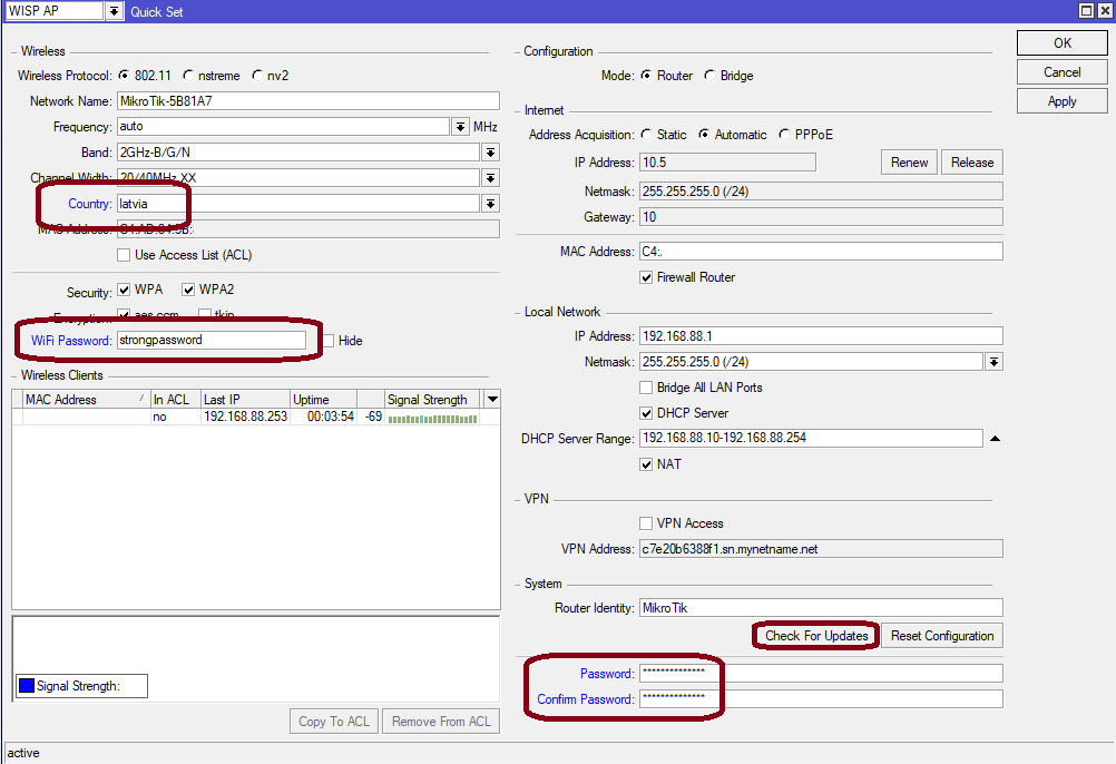
- Click the "Check for updates" button and update your RouterOS software to the latest version, the device needs to have an active Internet connection.
- After the update set your country, to apply country regulation settings.
- Set your WiFi password.
- Set the router password.
Expansion slots and ports
- 10/100 Ethernet port, supporting automatic cross/straight cable correction (Auto MDI/X). Either straight or crossover cable can be used for connecting to other network devices.
- External SMA antenna connector already connected to the LR card.
- Automotive connector. Pinout: A - reserved for future use (orange), B - reserved for future use (blue), C - ground (black), D – power in (red).
- MiniPCIe slot with an integrated LR2 card.
- Integrated Wireless module operating at 2.4 GHz, 802.11b/g/n protocol.
- Mini-SIM Slot.
Powering
The device accepts power in the following ways:
- Ethernet port accepts passive PoE 9-30 V DC ⎓.
- Direct-input power jack (5.5 mm outside and 2 mm inside, female, pin positive plug) accepts 9-30 V DC⎓.
- Automotive connector 9-30 V DC⎓.
The power consumption under maximum load can reach 8 W.
Connecting to a PoE Adapter:
- Connect the Ethernet cable from the device to the PoE+DATA port of the PoE adapter.
- Connect an Ethernet cable from your local network (LAN) to the PoE adapter.
- Connect the power cord to the adapter, and then plug the power cord into a power outlet.
Mounting
The device can be mounted in several ways: pole, wall, ceiling or it can be placed in a specially designed Mikrotik holder which comes with the package. The package also includes a drill hole template with detailed mounting instructions, to help you with the Ethernet cable installation and attachment to a ceiling or a wall. Steel bracket to put on the other side of a dropdown ceiling tile and two screws and wall anchors. Zip ties or steel clamps for mounting on the pole.
The IP rating scale for this device is IP54. When mounting outdoors, please ensure that any cable openings are directed downwards. We recommend using the POE injector and proper grounding with a Cat6 shielded cable. When using and installing this device please pay attention to the Maximum Permissible Exposure (MPE) safety distance with a minimum of 20 cm between the radiator and your body.
Mounting on the mast or pole:
* It's recommended to use electrical tape to increase friction between materials.
- Mount plastic tie straps to steel bracket guiding them through holes.
- Mount bracket to the device.
- Secure them with a screw.
- Mount and align the device on the pole or mast.
- Guide Ethernet cable through the opening and connect to the Ethernet port.
- Close bottom latch and secure with a screw.
It's recommended to secure an Ethernet cable to the pole using zip ties. With the distance from the device approximately 30 cm.
Mounting unit on the wall:
- Use included a template to mark spots for drilling holes. And if needed for Ethernet cable. Align accordingly, it will depend on how the device will be mounted finally.
- Insert dowels if needed, depends on wall structure and material.
- Place included a steel bracket on the wall.
- Use screws to secure it in place.
- Extend your Ethernet cable through the opening and connect to the Ethernet port.
- Mount the device on the steel bracket
- Secure it in place with the screw.
- Close bottom latch.
Avoid mounting the device on the low ground spot, as you won't be able to attach and close the bottom latch.
Mounting on the ceiling:
A Special bracket is included in the package to mount on the drop ceiling. As it consists of two parts, to be attached on both sides of the ceiling tile.
- Use the template to mark spots for holes.
- Place both mounting brackets on the spot.
- Secure them together using screws.
Continue assembling in the same manner if mounting on the wall.
- Extend your Ethernet cable through the opening and connect to the Ethernet port.
- Mount the device on the steel bracket.
- Secure it in place with the screw.
- Close bottom latch.
Bottom Lid
- The bottom lid is secured in place with the captive screw.

- Use a Torx T20 screwdriver to unscrew it, but do not remove the screw completely.

- Pull the cover in the opposite direction from the device to remove it.

- Reassemble.
Configuration
To set the configuration for LR please connect to the device and log in with your web browser or use a mobile application. Two easy steps to follow:
First step:
- Once logged in, Quick Set will be selected, please switch to WebFig on the right side of the screen. If the configuration is done through a mobile application then click on the gear symbol on the right side of the screen to open up an advanced menu.
- On the left side menu please find and select the section "Lora".
- On the newly opened window select the Servers tab.
- Click + to add a new server configuration.
- A new window will appear and you will have to enter:
Name: (Server name)
Address: (Server address)
Up port: (Usually it's 1700)
Down port: (Usually it's 1700)
- Click OK to save.
Second step:
- Select the Device tab on the previous window.
- Double-click or tap on the line to configure.
- Choose the previously entered network on the drop-down menu.
- Click on the button Enable to enable the gateway.
- Click OK to save.
- The configuration is done.
We recommend clicking the "Check for updates" button in the QuickSet menu, as updating your RouterOS software to the latest version ensures the best performance and stability. For wireless models, please make sure you have selected the country where the device will be used, to conform with local regulations.
RouterOS includes many configuration options in addition to what is described in this document. We suggest starting here to get yourself accustomed to the possibilities: https://mt.lv/help. In case IP connection is not available, the Winbox tool (https://mt.lv/winbox) can be used to connect to the MAC address of the device from the LAN side (all access is blocked from the Internet port by default).
For recovery purposes, it is possible to boot the device for reinstallation, see section Buttons and Jumpers.
MikroTik mobile app
Use the MikroTik smartphone app to configure your router in the field, or to apply the most basic initial settings for your MikroTik home access point.

- Scan QR code and choose your preferred OS.
- Install and open application.
- By default, the IP address and user name will be already entered.
- Click Connect to establish a connection to your device through a wireless network.
- Choose Quick setup and the application will guide you through all basic configuration settings in a couple of easy steps.
- An advanced menu is available to fully configure all necessary settings.
Antenna usage
We recommend using an external antenna, the "LR Antenna kit" - which can be obtained separately. The antenna kit has a pole mount and cable ready to use with LR cards. https://mikrotik.com/product/lora_antenna_kit
SMA connector located under the bottom door is already connected to the LR card and ready to be used. Please see the Mounting section on how to remove the door.
Please connect and disconnect the antenna, when the device is turned off!
Internal antenna 2 dBi can be used for setups where the distance to the gateway is closer than 1km. By default, the antenna is not connected to the card! To use an internal antenna:
- Open bottom door (see "Mounting").

- Use the PH2 screwdriver to remove the screw.
- Disassemble the upper case from the bottom by sliding them to opposite sides.

- Locate the internal antenna cable and replace it with the SMA cable connector on the LR card.

- Reassembly.
Buttons and jumpers
The reset button has three functions:
- Hold this button during boot time until LED light starts flashing, release the button to reset RouterOS configuration (total 5 seconds).
- Keep holding for 5 more seconds, LED turns solid, release now to turn on CAP mode. The device will now look for a CAPsMAN server (total 10 seconds).
- Or Keep holding the button for 5 more seconds until LED turns off, then release it to make the RouterBOARD look for Netinstall servers (total 15 seconds).
Regardless of the above option used, the system will load the backup RouterBOOT loader if the button is pressed before power is applied to the device. Useful for RouterBOOT debugging and recovery.
Accessories
The package includes the following accessories that come with the device:
- EU/US Switching Power Supply 24 V ⎓, 0.8 A, 19.2 W, 85.3 %, VI, cable:150 cm Hor CMC.
- WAP desk bracket.
- WAP outdoor case bracket AL, white.
- POE Injector cable.
- Cable (H4130-04PDB000R 3 mm 2x2P Housing) to (StripJacket 5 cm+WireEnd Strip/Tin 1 cm) 24 AWG.
- Hose Clamp, 35-70 mm, W4.
- K-52 fastening set.
- WAP-drill-template, paper brochure.
Operating system support
The device supports RouterOS software version 6.48.3. The specific factory-installed version number is indicated in the RouterOS menu /system resource. Other operating systems have not been tested.
RouterOS LR support is limited to MikroTik LR cards, it does not support 3rd party Lora cards.