LtAP LR8 LTE kit (RBLtAP-2HnD&R11e-LTE&LR8)
Quickstart
Please follow these quick steps to set up your device:
- Open the bottom lid;
- Insert the SIM card into the SIM 2 slot (middle);
- Connect the device to the power source;
- Connect with your computer to the MikroTik wireless network;
- Open https://192.168.88.1 in your web browser to start the configuration;
- The user name: admin and there is no password set, by default;
- Once connected, in the QuickSet LTE AP menu, enter your PIN code https://mt.lv/configuration;
- Upgrade the RouterOS software to the latest version https://mt.lv/upgrade;
- Connect again and in the QuickSet LTE AP menu set your wireless network password;
- Choose your country on the left side of the screen, to apply country regulation settings;
- Secure your device and set a strong password.
- Find your LR Gateway ID on the label within the product and register it in your Network Server.
Extension slots and ports

- Built-in 2 GHz wireless access point module, AP/station/bridge/p2p modes are supported. Onboard PIF antennas built-in, as well as MMCX connectors for external antennas (software selectable).
- Two miniPCIe slots and three SIM slots.
- Built-in GPS module with an external SMA connector.
- Gigabit Ethernet port, supporting automatic cross/straight cable correction (Auto MDI/X). Either straight or crossover cable can be used for connecting to other network devices. The Ethernet port accepts 12-30 V DC powering from a passive PoE injector.
- One DB9 RS232 serial port for serial console access. Configured as 115200 bit/s, 8 data bits, 1 stop bit, no parity.
- One USB 2.0 port.
- R11e-LR8, miniPCIe card with external SMA connector.
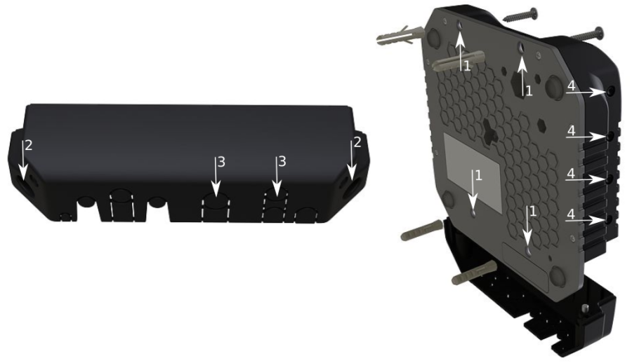
Mounting
- It is possible to attach the device to a wall, using the provided four screws and designed four holes on the unit.
- The ports are protected with a small door, that is held in place with two screws. Remove to access Ethernet ports, antenna connector, SIM slots, etc.
- The door has cut-out places for all available ports, so you can guide through all necessary cables, but please only break out the openings that you will use.
- Several places for external antennas are provided on the case, use an appropriate size drill, to make them available. Be careful and measure the chosen antenna, so that it does not touch the internal PCB board when installed.
The device can be used both indoors and outdoors. The IP rating scale of IP54.
If you intend to mount outdoors, please ensure that any cable openings are directed downwards. The Mounting direction is indicated on the device with an arrow pointing up. Use POE injector and proper grounding. Recommended using Cat6 shielded cable.
Warning! This equipment should be installed and operated with a minimum distance of 30 cm between the device and your body. Operation of this equipment in the residential environment could cause radio interference.
The device enclosure has places where you can drill openings for external LTE and GPS antennas. Use a drill to make holes that are appropriate for the antenna cable used.
Configuration
We recommend clicking the "Check for updates" button and updating your RouterOS software to the latest version to ensure the best performance and stability. RouterOS includes many configuration options in addition to what is described in this document. We suggest starting here to get yourself accustomed to the possibilities: https://mt.lv/help. In case IP connection is not available, the Winbox tool (https://mt.lv/winbox) can be used to connect to the MAC address of the device from the LAN side (all access is blocked from the internet port by default). For recovery purposes, it is possible to boot the device from a network, see the section LtAP kit-series#Reset button.
GPS
The built-in GPS module requires an external antenna to be used (SMA connector is already mounted behind the unit door). Please see the LtAP kit-series#Mounting section on how to remove the door.
Attention the GPS uses an active antenna, only connect and disconnect the antenna, when the device is turned off!
Supports - GPS, GLONASS, BeiDou, Galileo).
Make sure that the GPS package is installed on your device. Check by following command /system package print. If not installed please download extra packages at our download page accordingly to your RouterOS version and install the GPS package by dragging it to the Files menu. Enable GPS and start working:
- Enabling - /system gps set enable=yes;
- Setting antenna to external - /system gps set gps-antenna-select=external;
- Checking configuration - /system gps print.
https://wiki.mikrotik.com/wiki/Manual:System/GPS
LR usage
For interface configuration please visit https://wiki.mikrotik.com/wiki/Manual:Interface/Lora
We recommend using our antenna kit, https://mikrotik.com/product/lora_antenna_kit
USB usage
When using an LR card the USB port can be used only for power delivery, it cannot be used together with an LR card.
Automotive connector usage
Powering
- Direct-input power jack (5.5 mm outside and 2 mm inside, female, pin positive plug) accepts 12-30 V DC ⎓ with provided 24 V, 1.2 A adapter.
- Ethernet port accepts passive Power over Ethernet 12-30 V DC ⎓ (compensate for the loss on cable, so more than 12 V recommended).
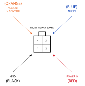
- The automotive connector can be used to power the device from regular 12/24 V ⎓ connections in automobiles and buses. The plug has four pins: bottom left (black) is the ground, bottom right is power in (red). The upper two (AUX) are reserved for future use.
The power consumption under maximum load can reach 12 W without attachments. Please attach ground (earth) wire to the screw under the door.
Connecting to a POE Adapter: (Not included)
- Connect the Ethernet cable from the device to the POE out port of the POE adapter.
- Connect an Ethernet cable from your LAN to the POE adapter.
- Connect the power cord to the adapter, and then plug the power cord into a power outlet.
Front status LED behavior
- Solid Blue – the device is powered on.
- Solid Green – user-defined LED, can be configured in system settings.
- Solid Green – state of GPS module.
- Solid Green– the set of five green LED, shows the signal strength of the cellular network.

miniPCIe slot
SIM card connectivity
- MiniPCIe 1 (top slot) supports PCIe and USB 2.0 cards but is shared with the USB 2.0 type A port (can use either the USB port or miniPCIe slot at the same time). It can be used only for SIM slot #1.
- MiniPCIe 2 (bottom slot) supports only USB (2.0 and 3.0) miniPCIe modems (no PCIe support). Uses SIM slot #2 and SIM slot #3. By default uses SIM slot #2.
- USB 2.0 type A port (can only be used if miniPCIe 1 is not used).
- To use the top miniPCIe slot with a USB type miniPCIe card, switch the USB connections to the miniPCIe slot: /system routerboard usb set type=mini-PCIe This will disable the USB 2.0 port on the front of the unit.
- Insert the SIM card into the top slot by a chip on the SIM card facing down. Bottom slots – with the chip facing up.
Please check if you are using the correct SIM slot. For the modem inserted in the bottom mini-pcie slot, you need to use either sim slot 2 or sim slot 3. And the used sim slot needs to be selected in RouterOS.
CLI command to select the sim slot: /system routerboard modem set sim-slot=2
Modem installation
This LtAP version is with the modem installed in the bottom slot. When installing an additional modem please use the upper slot. In this case, an internal antenna is connected to the bottom modem.
Installing a miniPCIe module should be done by a qualified person, please follow safety precautions when handling electrical equipment:
- Use a wrist grounding strap when unpacking and working with electrical components to avoid electrical discharge (ESD) damage;
- Remove six screws on the bottom of the case and lift off the top part of the case. Note that antenna cables are connected to the bottom modem;
- Locate the miniPCIe slot and remove two factory attached screws;
- Attach provided a thick thermal pad to the card, and install the card into miniPCIe slot so that thermal pad is between PCB and card;
- The secure card in place using previously removed two screws;
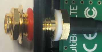
- Guide your antenna cables through openings near the GPS connector and connect to your modem. Recommended using silicone rubber to secure connectors in place.
- Attach a thinner thermal pad to the top of the card;
- When using external antennas, connectors can be attached on the case sides, to make openings use a 6.5 mm drill bit, please see LtAP kit-series#Mounting section part 4;
- Please see the picture below for reference on how to place rubber seals for best water protection;
- Reassembly in backorder. Tightening torque for PCB screws 0.3 Nm, case cover/enclosure screws 0.5 Nm.
After you have reinserted the device into the case and secured it with the screws that were removed earlier, slide in the SIM cards from your mobile operator into the SIM slots, with the chips facing as shown on the port label. The slot accepts miniSIM (2FF). SIM slots 2 and 3 apply to the bottom miniPCIe slot and can be switched in RouterOS "/system routerboard sim" menu.
Reset button
- Hold this button during boot time until LED light starts flashing, release the button to reset RouterOS configuration (total 5 seconds).
- Keep holding for 5 more seconds, LED turns solid, release now to turn on CAP mode. The device will now look for a CAPsMAN server (total 10 seconds).
- Or keep holding the button for 5 more seconds until LED turns off, then release it to make the RouterBOARD look for Netinstall servers (total 15 seconds).
Regardless of the above option used, the system will load the backup RouterBOOT loader if the button is pressed before power is applied to the device. Useful for RouterBOOT debugging and recovery.
Accessories
Package includes accessories that come with the device:
- K-67 fastening set. Includes four screws 4x25 mm, four dowels 6x30 mm.
- Cable DC ⎓ (H4130-04PDB000R 3 mm 2x2P Housing) to (StripJacket 5 cm+WireEnd Strip/Tin 1 cm) 24 AWG (Black/Red/Blue/Orange) 0.35 m.
- EU/US Switching Power Supply 24 V, 1.2 A, 28.8 W, 86.8%, VI, DC ⎓ cable: 220 cm RA DC plug mod Hor CMC shorter plug.
Operating system support
The device supports RouterOS software version 6.47.6. The specific factory-installed version number is indicated in the RouterOS menu /system resource. Other operating systems have not been tested.
MikroTik mobile app
Use the MikroTik smartphone app to configure your router in the field, or to apply the most basic initial settings for your MikroTik home access point.

- Scan QR code and choose your preferred OS.
- Install and open application.
- By default, the IP address and user name will be already entered.
- Click Connect to establish a connection to your device through a wireless network.
- Choose Quick setup and application will guide you through all basic configuration settings in a couple of easy steps.
Safety Warnings
Before you work on any equipment, be aware of the hazards involved with electrical circuitry, and be familiar with standard practices for preventing accidents.
Read the installation instructions before connecting the system to the power source.
This equipment is to be installed by trained and qualified personnel, as per these installation instructions. The installer is responsible for obtaining any required local or national safety inspections of the structural integrity of the installation by the local authority/inspection department.
All installation methods for mounting an access point on any wall surface is subject to the acceptance of local jurisdiction.
The Installation of the equipment must comply with local and national electrical codes.
This unit is intended to be mounted outdoors on a pole. Please read the mounting instructions carefully before beginning installation. Failure to use the correct hardware and configuration or to follow the correct procedures could result in a hazardous situation to people and damage to the system.
We cannot guarantee that no accidents or damage will occur due to the improper use of the device. Please use this product with care and operate at your own risk.
Notice
- The Frequency band 5.470-5.725 GHz isn’t allowed for commercial use.
- In case WLAN devices work with different ranges than the above regulations, then a customized firmware version from the manufacturer/supplier is required to be applied to the end-user equipment and also prevent the end-user from reconfiguration.
- For Outdoor Usage: End-user requires approval/license from the NTRA.
- Datasheet for any device is available on the official manufacturer website.
- Products with the letters “EG” at the end of their serial number have their wireless frequency range limited to 2.400 – 2.4835 GHz, the TX power is limited to 20dBm (EIRP).
- Products with the letters “EG” at the end of their serial number have their wireless frequency range limited to 5.150 – 5.250 GHz, the TX power is limited to 23dBm (EIRP).
- Products with the letters “EG” at the end of their serial number have their wireless frequency range limited to 5.250 – 5.350 GHz, the TX power is limited to 20dBm (EIRP).
Please make sure the device has a lock package (firmware version from the manufacturer) which is required to be applied to the end-user equipment to prevent the end-user from reconfiguration. The product will be marked with country code “-EG”. This device needs to be upgraded to the latest version to ensure compliance with local authority regulations! It is the end users responsibility to follow local country regulations, including operation within legal frequency channels, output power, cabling requirements, and Dynamic Frequency Selection (DFS) requirements. All MikroTik radio devices must be professionally installed.
CE Declaration of Conformity
BG | С настоящото Mikrotīkls SIA декларира, че този тип радиосъоръжение RouterBOARD е в съответствие с Директива 2014/53/ЕС. Цялостният текст на ЕС декларацията за съответствие може да се намери на следния интернет адрес: https://mikrotik.com/products |
CS | Tímto Mikrotīkls SIA prohlašuje, že typ rádiového zařízení RouterBOARD je v souladu se směrnicí 2014/53/EU. Úplné znění EU prohlášení o shodě je k dispozici na této internetové adrese: https://mikrotik.com/products |
DA | Hermed erklærer Mikrotīkls SIA, at radioudstyrstypen RouterBOARD er i overensstemmelse med direktiv 2014/53/EU. EU-overensstemmelseserklæringens fulde tekst kan findes på følgende internetadresse: https://mikrotik.com/products |
DE | Hiermit erklärt Mikrotīkls SIA, dass der Funkanlagentyp RouterBOARD der Richtlinie 2014/53/EU entspricht. Der vollständige Text der EU-Konformitätserklärung ist unter der folgenden Internetadresse verfügbar: https://mikrotik.com/products |
EL | Με την παρούσα ο/η Mikrotīkls SIA, δηλώνει ότι ο ραδιοεξοπλισμός RouterBOARD πληροί την οδηγία 2014/53/ΕΕ. Το πλήρες κείμενο της δήλωσης συμμόρφωσης ΕΕ διατίθεται στην ακόλουθη ιστοσελίδα στο διαδίκτυο: https://mikrotik.com/products |
EN | Hereby, Mikrotīkls SIA declares that the radio equipment type RouterBOARD is in compliance with Directive 2014/53/EU. The full text of the EU declaration of conformity is available at the following internet address: https://mikrotik.com/products |
ES | Por la presente, Mikrotīkls SIA declara que el tipo de equipo radioeléctrico RouterBOARD es conforme con la Directiva 2014/53/UE. El texto completo de la declaración UE de conformidad está disponible en la dirección Internet siguiente: https://mikrotik.com/products |
ET | Käesolevaga deklareerib Mikrotīkls SIA, et käesolev raadioseadme tüüp RouterBOARD vastab direktiivi 2014/53/EL nõuetele. ELi vastavusdeklaratsiooni täielik tekst on kättesaadav järgmisel internetiaadressil: https://mikrotik.com/products |
FI | Mikrotīkls SIA vakuuttaa, että radiolaitetyyppi RouterBOARD on direktiivin 2014/53/EU mukainen. EU-vaatimustenmukaisuusvakuutuksen täysimittainen teksti on saatavilla seuraavassa internetosoitteessa: https://mikrotik.com/products |
FR | Le soussigné, Mikrotīkls SIA, déclare que l'équipement radioélectrique du type RouterBOARD est conforme à la directive 2014/53/UE. Le texte complet de la déclaration UE de conformité est disponible à l'adresse internet suivante: https://mikrotik.com/products |
HR | Mikrotīkls SIA ovime izjavljuje da je radijska oprema tipa RouterBOARD u skladu s Direktivom 2014/53/EU. Cjeloviti tekst EU izjave o sukladnosti dostupan je na sljedećoj internetskoj adresi: https://mikrotik.com/products |
HU | Mikrotīkls SIA igazolja, hogy a RouterBOARD típusú rádióberendezés megfelel a 2014/53/EU irányelvnek. Az EU-megfelelőségi nyilatkozat teljes szövege elérhető a következő internetes címen: https://mikrotik.com/products |
IT | Il fabbricante, Mikrotīkls SIA, dichiara che il tipo di apparecchiatura radio RouterBOARD è conforme alla direttiva 2014/53/UE. Il testo completo della dichiarazione di conformità UE è disponibile al seguente indirizzo Internet: https://mikrotik.com/products |
IS | Hér með lýsir Mikrotīkls SIA því yfir að RouterBOARD er í samræmi við grunnkröfur og aðrar kröfur, sem gerðar eru í tilskipun 2014/53/EU. Fullur texti ESB samræmisyfirlýsingar er að finna á eftirfarandi veffangi: https://mikrotik.com/products |
LT | Aš, Mikrotīkls SIA, patvirtinu, kad radijo įrenginių tipas RouterBOARD atitinka Direktyvą 2014/53/ES. Visas ES atitikties deklaracijos tekstas prieinamas šiuo interneto adresu: https://mikrotik.com/products |
LV | Ar šo Mikrotīkls SIA deklarē, ka radioiekārta RouterBOARD atbilst Direktīvai 2014/53/ES. Pilns ES atbilstības deklarācijas teksts ir pieejams šādā interneta vietnē: https://mikrotik.com/products |
MT | B'dan, Mikrotīkls SIA, niddikjara li dan it-tip ta' tagħmir tar-radju RouterBOARD huwa konformi mad-Direttiva 2014/53/UE. It-test kollu tad-dikjarazzjoni ta' konformità tal-UE huwa disponibbli f'dan l-indirizz tal-Internet li ġej: https://mikrotik.com/products |
NL | Hierbij verklaar ik, Mikrotīkls SIA, dat het type radioapparatuur RouterBOARD conform is met Richtlijn 2014/53/EU. De volledige tekst van de EU-conformiteitsverklaring kan worden geraadpleegd op het volgende internetadres: https://mikrotik.com/products |
NO | Mikrotīkls SIA erklærer herved at utstyret RouterBOARD er i samsvar med de grunnleggende krav og øvrige relevante krav i direktiv 2014/53/EU. Den fulle teksten til EU-samsvarserklæringen er tilgjengelig på følgende internettadresse: https://mikrotik.com/products |
PL | Mikrotīkls SIA niniejszym oświadcza, że typ urządzenia radiowego RouterBOARD jest zgodny z dyrektywą 2014/53/UE. Pełny tekst deklaracji zgodności UE jest dostępny pod następującym adresem internetowym: https://mikrotik.com/products |
PT | O(a) abaixo assinado(a) Mikrotīkls SIA declara que o presente tipo de equipamento de rádio RouterBOARD está em conformidade com a Diretiva 2014/53/UE. O texto integral da declaração de conformidade está disponível no seguinte endereço de Internet: https://mikrotik.com/products |
RO | Prin prezenta, Mikrotīkls SIA declară că tipul de echipamente radio RouterBOARD este în conformitate cu Directiva 2014/53/UE. Textul integral al declarației UE de conformitate este disponibil la următoarea adresă internet: https://mikrotik.com/products |
SK | Mikrotīkls SIA týmto vyhlasuje, že rádiové zariadenie typu RouterBOARD je v súlade so smernicou 2014/53/EÚ. Úplné EÚ vyhlásenie o zhode je k dispozícii na tejto internetovej adrese: https://mikrotik.com/products |
SL | Mikrotīkls SIA potrjuje, da je tip radijske opreme RouterBOARD skladen z Direktivo 2014/53/EU. Celotno besedilo izjave EU o skladnosti je na voljo na naslednjem spletnem naslovu: https://mikrotik.com/products |
SV | Härmed försäkrar Mikrotīkls SIA att denna typ av radioutrustning RouterBOARD överensstämmer med direktiv 2014/53/EU. Den fullständiga texten till EU-försäkran om överensstämmelse finns på följande webbadress: https://mikrotik.com/products |
WLAN | Operating Frequency / Maximum output power Betriebsfrequenz / maximale Ausgangsleistung Fréquence de fonctionnement / puissance de sortie maximale Frequenza operativa / massima potenza di uscita Frecuencia de funcionamiento / potencia de salida máxima Рабочая частота / максимальная выходная мощность | 2400-2483.5 MHz / 20 dBm |
LR (SRD) | 863-870 MHz / 14 dBm |
This MikroTik device meets Maximum WLAN and LTE transmit power limits per ETSI regulations. For more detailed information see Declaration of Conformity above / Dieses MikroTik-Gerät erfüllt die maximalen WLAN- und LTE-Sendeleistung Grenzwerte gemäß ETSI-Bestimmungen. Weitere Informationen finden Sie oben unter Konformitätserklärung / Cet appareil MikroTik respecte les limites maximales de puissance de transmission WLAN et LTE conformément aux réglementations ETSI. Pour plus d'informations, voir la déclaration de conformité ci-dessus / Questo dispositivo MikroTik è conforme ai limiti massimi di potenza di trasmissione WLAN e LTE in conformità con le normative ETSI. Per ulteriori informazioni, consultare la dichiarazione di conformità sopra / Este dispositivo MikroTik cumple con los límites máximos de potencia de transmisión WLAN y LTE de acuerdo con las regulaciones ETSI. Para obtener más información, consulte la declaración de conformidad anterior / Это устройство MikroTik соответствует максимальным пределам мощности передачи WLAN и LTE в соответствии с правилами ETSI. Для получения дополнительной информации см. Декларацию соответствия выше.