...
You must also specify which VLANs should be sent out to the trunk port with a VLAN tag. Use the tagged-ports property to set up a trunk port:
...
| Code Block | ||
|---|---|---|
| ||
/interface ethernet switch vlan add ports=ether2,ether6 vlan-id=200 add ports=ether2,ether7 vlan-id=300 add ports=ether2,ether8 vlan-id=400 |
After a valid VLAN configuration has been set up, you can enable unknown/invalid VLAN filtering:
...
| Note |
|---|
It is possible to use the built-in switch chip and the CPU at the same time to create a Switch-Router setup, where a device acts as a switch and as a router at the same time. You can find a configuration example in the CRS-Router guide. |
Example 2 (Trunk and Hybrid
...
Ports)
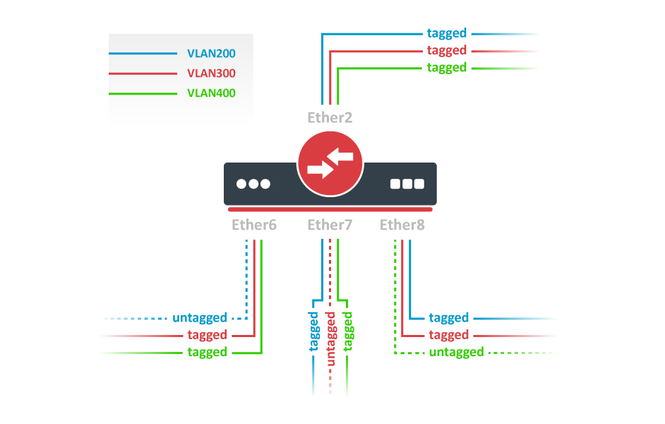
Switch together the required ports:
...
| Code Block | ||
|---|---|---|
| ||
/interface ethernet switch vlan add ports=ether2,ether6,ether7,ether8 vlan-id=200 learn=yes add ports=ether2,ether6,ether7,ether8 vlan-id=300 learn=yes add ports=ether2,ether6,ether7,ether8 vlan-id=400 learn=yes |
After a valid VLAN configuration has been set up, you can enable unknown/invalid VLAN filtering:
| Code Block | ||
|---|---|---|
| ||
/interface ethernet switch set drop-if-invalid-or-src-port-not-member-of-vlan-on-ports=ether2,ether6,ether7,ether8 |
Protocol Based VLAN

Switch together the required ports:
...
| Warning |
|---|
Internally all MAC addresses in MAC-based VLANs are hashed, certain MAC addresses can have the same hash, which will prevent a MAC address from being loaded into the switch chip if the hash matches with a hash from a MAC address that has been already loaded, for this reason, it is recommended to use Port bases VLANs in combination with MAC-based VLANs. This is a hardware limitation. |
Switch together the required ports:
...
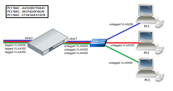
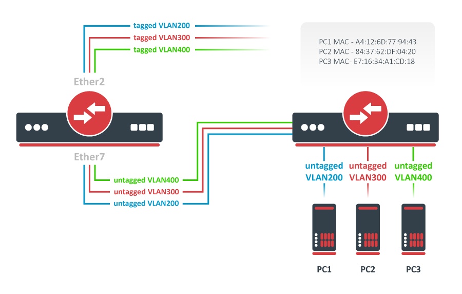
Add MAC-to-VLAN mapping entries in the MAC-based VLAN table:
| Code Block | ||
|---|---|---|
| ||
/interface ethernet switch mac-based-vlan add src-mac=A4:12:6D:77:94:43 new-customer-vid=200 add src-mac=84:37:62:DF:04:20 new-customer-vid=300 add src-mac=E7:16:34:A1:CD:18 new-customer-vid=400 |
Add VLAN200, VLAN300, and VLAN400 tagging on the ether2 port to create it as a VLAN trunk port:
| Code Block | ||
|---|---|---|
| ||
/interface ethernet switch egress-vlan-tag add tagged-ports=ether2 vlan-id=200 add tagged-ports=ether2 vlan-id=300 add tagged-ports=ether2 vlan-id=400 |
...
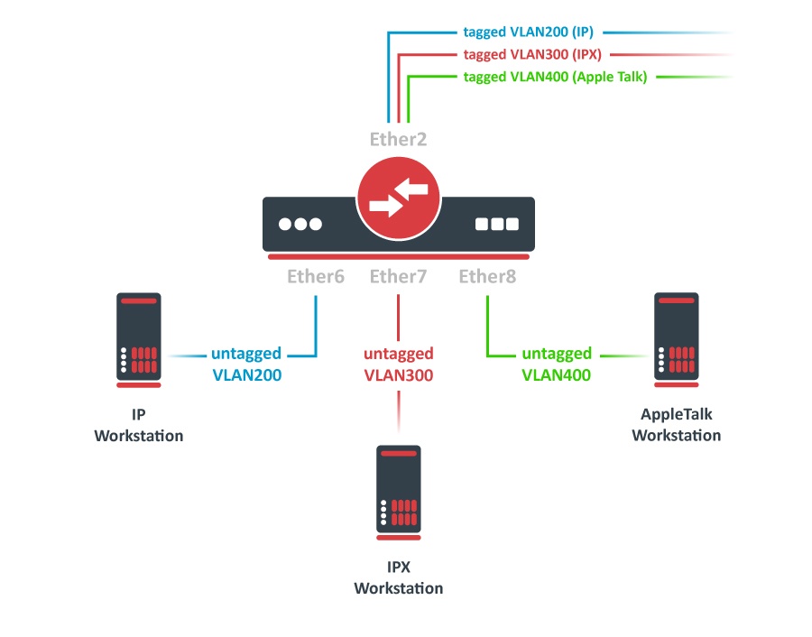
InterVLAN routing configuration consists of two main parts – VLAN tagging in switch-chip and routing in RouterOS. This configuration can be used in many applications by combining it with DHCP server, Hotspot, PPP, and other features for each VLAN.
...
| Warning |
|---|
Make sure the VLAN interfaces are created on top of the bridge interface instead of any of the physical interfaces. If the VLAN interfaces are created on a slave interface, then the packet might not be received correctly and therefore routing might fail. More detailed information can be found in the the VLAN interface on a slave interface manual page. |
Add IP addresses to on created the VLAN interfaces. In this example, three 192.168.x.1 addresses are added to VLAN200, VLAN300, and VLAN400 interfaces:
| Code Block | ||
|---|---|---|
| ||
/ip address add address=192.168.20.1/24 interface=VLAN200 add address=192.168.30.1/24 interface=VLAN300 add address=192.168.40.1/24 interface=VLAN400 |
...
VLAN membership is defined in the VLAN table. Adding entries with VLAN ID and ports makes that VLAN traffic valid on those ports. After a valid VLAN configuration has been setupset up, unknown/invalid VLAN filtering can be enabled. This VLAN filtering configuration example applies to the InterVLAN Routing setup.
| Code Block | ||
|---|---|---|
| ||
/interface ethernet switch vlan add ports=switch1-cpu,ether6 vlan-id=200 add ports=switch1-cpu,ether7 vlan-id=300 add ports=switch1-cpu,ether8 vlan-id=400 |
...
VLAN Tunneling (Q-in-Q)
This example covers a typical VLAN tunneling use case where service provider devices add another VLAN tag for independent forwarding in the mean time meantime allowing customers to use their own VLANs.
| Note |
|---|
This example contains only the Service VLAN tagging part. It is recommended to additionally set Unknown/Invalid VLAN filtering configuration on ports. |

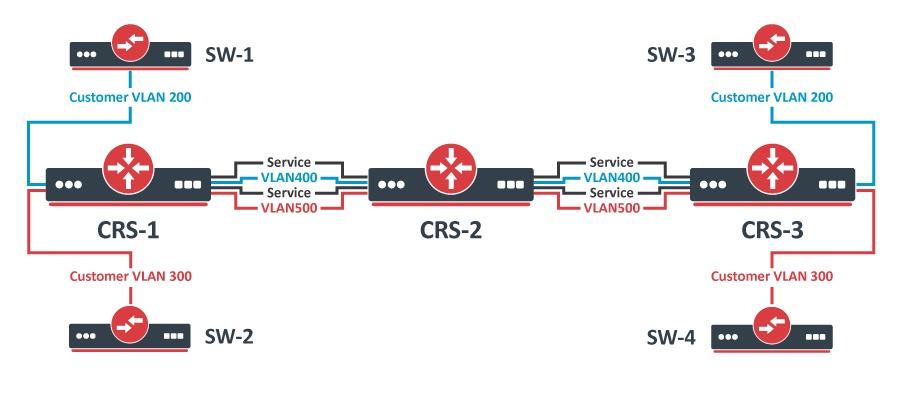
CRS-1: The first switch on the edge of the service provider network has to properly indentify identify traffic from customer VLAN id on port and assign new service VLAN id with ingress VLAN translation rules. VLAN trunk port configuration for service provider VLAN tags is in the same egress-vlan-tag table. The main difference from basic Port-Based VLAN configuration is that the CRS switch-chip has to be set to do forwarding according to service (outer) VLAN id instead of customer (inner) VLAN id.
...
CRS-3: The third switch has a similar configuration to CRS-1:
- Ports in a switch group using a bridge;
- Ingress VLAN translation rules to define new service VLAN assingments assignments on ports;
- tagged-ports for service provider VLAN trunks;
- CRS switch-chip set to use service VLAN id in switching lookup.
...
| Note |
|---|
Since the switch is set to look up VLAN ID based on service tag, which is overridden with a different EtherType, then VLAN filtering is only done on the outer tag of a packet, the inner tag is not checked. |
Mirroring
...

The Cloud Router Switches support three types of mirroring. Port-based mirroring can be applied to any of switch-chip ports, VLAN-based mirroring works for all specified VLANs regardless of switch-chip ports, and MAC-based mirroring copies traffic sent or received from specific device reachable from the port configured in Unicast Forwarding Database.
Port-Based Mirroring
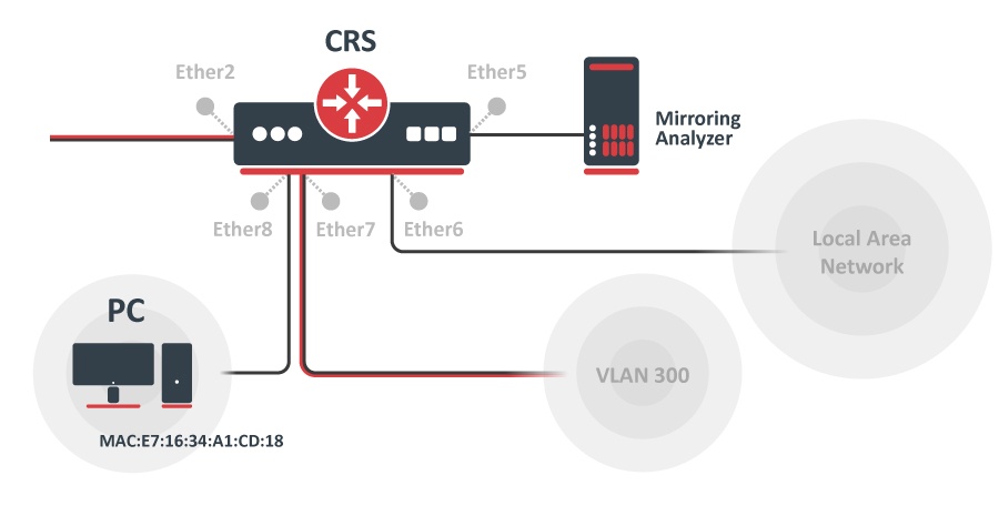
The first configuration sets the ether5 port as a mirror0 analyzer port for both ingress and egress mirroring, mirrored traffic will be sent to this port. Port-based ingress and egress mirroring are enabled from the ether6 port.
| Code Block | ||
|---|---|---|
| ||
/interface ethernet switch set ingress-mirror0=ether5 egress-mirror0=ether5 /interface ethernet switch port set ether6 ingress-mirror-to=mirror0 egress-mirror-to=mirror0 |
...
The third configuration also requires ports to be switched in a group. Mirroring configuration sets ether5 port as a mirror0 analyzer port and sets mirror0 port to be used when mirroring from Unicast Forwarding database occurs. The entry from the Unicast Forwarding database enables mirroring for packets with source or destination MAC address E7:16:34:A1:CD:18 from ether8 port.
| Code Block | ||
|---|---|---|
| ||
/interface bridge add name=bridge1 /interface bridge port add bridge=bridge1 interface=ether2 hw=yes add bridge=bridge1 interface=ether8 hw=yes /interface ethernet switch set ingress-mirror0=ether5 fdb-uses=mirror0 /interface ethernet switch unicast-fdb add port=ether8 mirror=yes svl=yes mac-address=E7:16:34:A1:CD:18 |
Trunking
...

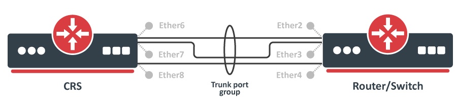
The Trunking in the Cloud Router Switches provides static link aggregation groups with hardware automatic failover and load balancing. IEEE802.3ad and IEEE802.1ax compatible Link Aggregation Control Protocol is not supported yet. Up to 8 Trunk groups are supported with up to 8 Trunk member ports per Trunk group.
...
| Note |
|---|
You can find a working example for trunking and port-based VLANs aton CRS VLANs with Trunks page. |
...
| Warning |
|---|
Bridge (R)STP is not aware of the underlying switch trunking configuration and some trunk ports can move to discarding or blocking state. When trunking member ports are connected to other bridges, you should either disable the (R)STP or filter out any BPDU between trunked devices (e.g. with ACL rules). |
...
Disabling MAC learning and configuring static MAC addresses gives the ability to control what exact devices can communicate to CRS1xx/2xx switches and through them.
Configuration requires a group of switched ports, disabled MAC learning on those ports, and static UFDB entries:
| Code Block | ||
|---|---|---|
| ||
/interface bridge add name=bridge1 /interface bridge port add bridge=bridge1 interface=ether2 hw=yes add bridge=bridge1 interface=ether6 hw=yes learn=no unknown-unicast-flood=no add bridge=bridge1 interface=ether7 hw=yes learn=no unknown-unicast-flood=no /interface ethernet switch unicast-fdb add mac-address=4C:5E:0C:00:00:01 port=ether6 svl=yes add mac-address=D4:CA:6D:00:00:02 port=ether7 svl=yes /interface ethernet switch acl add action=drop src-mac-addr-state=sa-not-found src-ports=ether6,ether7 table=egress |
CRS1xx/2xx switches also allow to learn one dynamic MAC per port to ensure only one end-user device is connected no matter of its MAC address:
| Code Block | ||
|---|---|---|
| ||
/interface ethernet switch port set ether6 learn-limit=1 set ether7 learn-limit=1 |
Isolation
...
Port Level Isolation

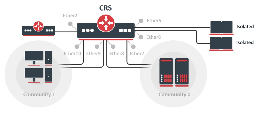
Port-level isolation is often used for Private VLAN, where:
- One or multiple uplink ports are shared among all users for accessing the gateway or router.
- Port group Isolated Ports is for guest users. Communication is through the uplink ports only.
- Port group Community 0 is for department A. Communication is allowed between the group members and through uplink ports.
- Port group Community X is for department X. Communication is allowed between the group members and through uplink ports.
The Cloud Router Switches use port-level isolation profiles for Private VLAN implementation:
- Uplink ports – Portport-level isolation profile 0
- Isolated ports – Portport-level isolation profile 1
- Community 0 ports - Portport-level isolation profile 2
- Community X (X <= 30) ports - Portport-level isolation profile X
...
The first part of port isolation configuration is setting the Uplink port – set a port profile to 0 for ether2:
...
| Code Block | ||
|---|---|---|
| ||
/interface ethernet switch port set ether7 isolation-leakage-profile-override=2 set ether8 isolation-leakage-profile-override=2 /interface ethernet switch port-isolation add port-profile=2 ports=ether2,ether7,ether8 type=dst /interface ethernet switch port set ether9 isolation-leakage-profile-override=3 set ether10 isolation-leakage-profile-override=3 /interface ethernet switch port-isolation add port-profile=3 ports=ether2,ether9,ether10 type=dst |
Protocol Level Isolation

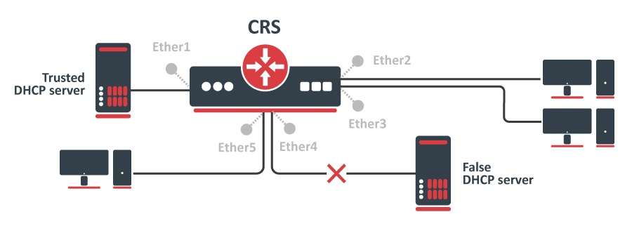
Protocol level isolation on CRS switches can be used to enchance enhance network security. For example, restricting DHCP traffic between the users and allowing it only to trusted DHCP server port ports can prevent security risks like DHCP spoofing attackattacks. The following example shows how to configure it on CRS.
...
And configure port isolation/leakage profile for selected Community (2) to allow DHCP traffic destined only to port where the trusted DHCP server is located. registration - status and traffic-type properties have to be set empty in order to apply restriction restrictions only for DHCP protocol.
| Code Block | ||
|---|---|---|
| ||
/interface ethernet switch port-isolation add port-profile=2 protocol-type=dhcpv4 type=dst forwarding-type=bridged ports=ether1 registration-status="" traffic-type="" |
...
In Strict Priority scheduling mode, the highest priority queue is served first. The queue number represents the priority and the queue with the highest queue number has the highest priority. Traffic is transmitted from the highest priority queue until the queue is empty, and then moves to the next highest priority queue, and so on. If no congestion is present on at the egress port, a packet is transmitted as soon as it is received. If congestion occurs on in the port where high-priority traffics keeps coming, the lower priority queues starve.
On all CRS switches the scheme where MAC based egress traffic scheduling is done according to internal Priority would be following: [MAC address] -> [QoS Group] -> [Priority] -> [Queue];
In this example, host1 (E7:16:34:00:00:01) and host2 (E7:16:34:00:00:02) will have higher priority 1 and the rest of the hosts will have lower priority 0 for transmitted traffic on port ether7. Note that CRS has a maximum of 8 queues per port.
...
Add UFDB entries to match specific MACs on ether7 and apply the QoS group1:
| Code Block | ||
|---|---|---|
| ||
/interface ethernet switch unicast-fdb add mac-address=E7:16:34:00:00:01 port=ether7 qos-group=group1 svl=yes add mac-address=E7:16:34:00:00:02 port=ether7 qos-group=group1 svl=yes |
...
| Code Block | ||
|---|---|---|
| ||
/interface bridge add name=bridge1 /interface bridge port add bridge=bridge1 interface=ether6 hw=yes add bridge=bridge1 interface=ether7 hw=yes add bridge=bridge1 interface=ether8 hw=yes |
Create a QoS group for use in UFDB:
...
Configure ether6, ether7, and ether8 port queues to work according to Strict Priority and QoS schemes only for VLAN-based QoS.
...
The same Ingress Port policer also can be used for the traffic storm control to prevent disruptions on Layer 2 ports caused by broadcast, multicast, or unicast traffic storms.
...
- Example with multiple packet types which includes ARP and ND protocols and unregistered multicast traffic. Unregistered multicast is traffic that is not defined in the Multicast Forwarding databaseDatabase.
| Code Block | ||
|---|---|---|
| ||
/interface ethernet switch ingress-port-policer add port=ether5 rate=5k meter-unit=packet packet-types=broadcast,arp-or-nd,unregistered-multicast |
...