...
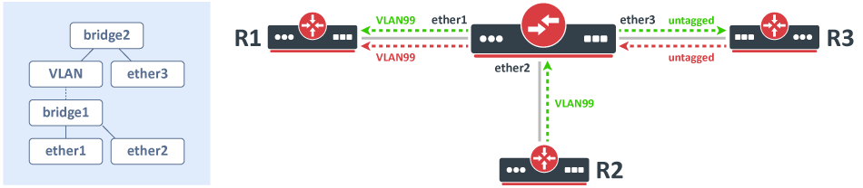
Consider the following scenario, you have a set of interfaces (don't have to be physical interfaces) and you want all of them to be in the same Layer2 segment, the solution is to add them to a single bridge, but you require that traffic from one port tags all traffic into a certain VLAN. This can be done by creating a VLAN interface on top of the bridge interface and by creating a separate bridge that contains this newly created VLAN interface and an interface, which is supposed to add a VLAN tag to all received traffic. A network diagram can be found below:
Configuration
...
In this case, both endpoints can be any type of device, we will assume that they are both Linux servers that are supposed to transfer a large amount of data. In such a scenario, you would have probably set something similar interface MTU to this 9000 on ServerA and ServerB :
| Code Block |
|---|
ip link set eth1 mtu 9000 |
And and on your Switch you have probably have set something similar to this:
...
Consider the following scenario, you want to transparently bridge two network segments together, either those are tunnel interfaces like EoIP, Wireless interfaces, Ethernet interface or any other kind of interfaces that can be added to a bridge. Such setups a setup allows you to seamlessly connect two devices together like there was only a physical cable between them, this is sometimes called a transparent bridge from DeviceA to DeviceB.
...
While the following configuration is relevant to AP1, AP2, ST1 and ST2:, where X corresponds to an IP address for each device.
| Code Block | ||
|---|---|---|
| ||
/interface bridge add name=bridge1 protocol-mode=none /interface bridge port add interface=ether1 bridge=bridge1 add interface=wlan1 bridge=bridge1 /ip address add address=192.168.1.X/24 interface=bridge1 |
...
Problem
While traffic is being forwarded properly between R1 and R2, load balancing, link failover is working properly as well, but devices between R1 and R2 are not always accessible or some of them are completely inaccessible (in most cases AP2 and ST2 are inaccessible). After examining the problem you might notice that packets do not always get forwarded over the required bonding slave and as a result, never is received by the device you are trying to access. This is a network design and bonding protocol limitation. As soon as a packet needs to be sent out through a bonding interface (in this case you might be trying to send ICMP packets to AP2 or ST2), the bonding interface will create a hash based on the selected bonding mode and transmit-hash-policy and will select an interface, through which to send the packet out, regardless if the destination is only reachable through a certain interface. Some devices will be accessible because the generated hash matches the interface, on which the device is located on, but it might not choose the needed interface as well, which will result in inaccessible device. Only broadcast bonding mode does not have this kind of protocol limitation, but this bonding mode has a very limited use case.
...
| Code Block | ||
|---|---|---|
| ||
/interface vlan add interface=ether1 name=VLAN_ether1 vlan-id=999 add interface=ether2 name=VLAN_ether2 vlan-id=999 /interface bonding add mode=balance-xor name=bond1 slaves=VLAN_ether1,VLAN_ether2 transmit-hash-policy=layer-2-and-3 /ip address add address=192.168.1.X/24 interface=bond1 add address=192.168.11.X/24 interface=ether1 add address=192.168.22.X/24 interface=ether2 |
AP1 and ST1 only needs need updated IP addresses to the correct subnet:
| Code Block | ||
|---|---|---|
| ||
/ip address add address=192.168.11.X/24 interface=bridge1 |
...
Consider the following scenario, you set up a link between two devices, this can be any link, an Ethernet cable, a wireless link, a tunnel or any other connection. You decide that you want to test the link's bandwidth, but for convenience reasons, you decide to start testing the link with the same devices that are running the link.
Problem
As soon as you start Bandwidth test or Traffic generator you notice that the throughput is much smaller than expected. For very powerful routers, which should be able to forward many Gigabits per second (Gbps) you notice that only a few Gigabits per second gets forwarded. The reason why this is happening is because of the testing method you are using, you should never test throughput on a router while using the same router for generating traffic because you are adding an additional load on the CPU that reduces the total throughput.
...