...
OSPF is Interior Gateway Protocol (IGP) designed to distribute routing information between routers belonging to the same Autonomous System (AS).
OSPF Protocol is based on link-state technology that has several advantages over distance-vector protocols such as RIP:
...
- OSPF is quite CPU and memory intensive due to the SPF algorithm and maintenance of multiple copies of routing information;
- more complex protocol to implement compared to RIP;
OSPF Terminology
Term definitions related to OSPF operations.
- Neighbor - connected (adjacent) router that is running OSPF with the adjacent interface assigned to the same area. Neighbors are found by Hello packets (unless manually configured).
- Adjacency - logical connection between a router and its corresponding DR and BDR. No routing information is exchanged unless adjacencies are formed.
- Link - link refers to a network or router interface assigned to any given network.
- Interface - physical interface on the router. The interface is considered as a link when it is added to OSPF. Used to build link database.
- LSA - Link State Advertisement, data packet contains link-state and routing information, that is shared among OSPF Neighbors.
- DR - Designated Router, chosen router to minimize the number of adjacencies formed. The option is used in broadcast networks.
- BDR -Backup Designated Router, hot standby for the DR. BDR receives all routing updates from adjacent routers, but it does not flood LSA updates.
- Area - areas are used to establish a hierarchical network.
- ABR - Area Border Router, router connected to multiple areas. ABRs are responsible for summarization and update suppression between connected areas.
- ASBR - Autonomous System Boundary Router, router connected to an external network (in a different AS). If you import other protocol routes into OSPF from the router it is now considered ASBR.
- NBMA - Non-broadcast multi-access, networks allow multi-access but have no broadcast capability. Additional OSPF neighbor configuration is required for those networks.
- Broadcast - Network that allows broadcasting, for example, Ethernet.
- Point-to-point - Network type eliminates the need for DRs and BDRs
- Router-ID - IP address used to identify OSPF router. If the OSPF Router-ID is not configured manually, a router uses one of the IP addresses assigned to the router as its Router-ID.
- Link State - The term link-state refers to the status of a link between two routers. It defines the relationship between a router's interface and its neighboring routers.
- Cost - Link-state protocols assign a value to each link called cost. the cost value depends on the speed of the media. A cost is associated with the outside of each router interface. This is referred to as interface output cost.
- Autonomous System - An autonomous system is a group of routers that use a common routing protocol to exchange routing information.
All of these terms are important for understanding the operation of the OSPF and they are used throughout the article.
Understanding OSPF Areas
A distinctive feature of OSPF is the possibility to divide AS into multiple routing Areas which contain their own set of neighbors.
Imagine a large network with 300+ routers and multiple links between them. Whenever link flaps or some other topology change happens in the network, this change will be flooded to all OSPF devices in the network resulting in a quite heavy load on the network and even downtime since network convergence may take some time for such a large network.
The introduction of areas allows for better resource management since topology change inside one area is not flooded to other areas in the network. The concept of areas enables simplicity in network administration as well as routing summarization between areas significantly reducing the database size that needs to be stored on each OSPF neighbor.
...
RouterOS implements following standards:
- RFC 2328 - OSPF Version 2
- RFC 3101 - The OSPF Not-So-Stubby Area (NSSA) Option
- RFC 3630 - Traffic Engineering (TE) Extensions to OSPF Version 2
- RFC 4577 - OSPF as the Provider/Customer Edge Protocol for BGP/MPLS IP Virtual Private Networks (VPNs)
- RFC 5329 - Traffic Engineering Extensions to OSPF Version 3
- RFC 5340 - OSPF for IPv6
- RFC 5643 - Management Information Base for OSPFv3
- RFC 6549 - OSPFv2 Multi-Instance Extensions
- RFC 6565 - OSPFv3 as a Provider Edge to Customer Edge (PE-CE) Routing Protocol
- RFC 6845 - OSPF Hybrid Broadcast and Point-to-Multipoint Interface Type
- RFC 7471 - OSPF Traffic Engineering (TE) Metric Extensions
Basic Configuration Example
To start OSPF v2 and v3 instances, the first thing to do is to add the instance and the backbone area:
| Code Block | ||
|---|---|---|
| ||
/routing ospf instance
add name=v2inst version=2 router-id=1.2.3.4
add name=v3inst version=3 router-id=1.2.3.4
/routing ospf area
add name=backbone_v2 area-id=0.0.0.0 instance=v2inst
add name=backbone_v3 area-id=0.0.0.0 instance=v3inst |
At this point, we can add a template. The template is used to match interfaces on which OSPF should be running, it can be done either by specifying network or interface directly.
| Code Block | ||
|---|---|---|
| ||
/routing ospf interface-template
add network=192.168.0.0/24 area=backbone_v2
add network=2001:db8::/64 area=backbone_v3
add network=ether1 area=backbone_v3 |
OSPF Terminology
Before we move on lets familiarise with terms important for understanding the operation of the OSPF. These terms will be used throughout the article.
- Neighbor - connected (adjacent) router that is running OSPF with the adjacent interface assigned to the same area. Neighbors are found by Hello packets (unless manually configured).
- Adjacency - logical connection between a router and its corresponding DR and BDR. No routing information is exchanged unless adjacencies are formed.
- Link - link refers to a network or router interface assigned to any given network.
- Interface - physical interface on the router. The interface is considered as a link when it is added to OSPF. Used to build link database.
- LSA - Link State Advertisement, data packet contains link-state and routing information, that is shared among OSPF Neighbors.
- DR - Designated Router, chosen router to minimize the number of adjacencies formed. The option is used in broadcast networks.
- BDR -Backup Designated Router, hot standby for the DR. BDR receives all routing updates from adjacent routers, but it does not flood LSA updates.
- Area - areas are used to establish a hierarchical network.
- ABR - Area Border Router, router connected to multiple areas. ABRs are responsible for summarization and update suppression between connected areas.
- ASBR - Autonomous System Boundary Router, router connected to an external network (in a different AS). If you import other protocol routes into OSPF from the router it is now considered ASBR.
- NBMA - Non-broadcast multi-access, networks allow multi-access but have no broadcast capability. Additional OSPF neighbor configuration is required for those networks.
- Broadcast - Network that allows broadcasting, for example, Ethernet.
- Point-to-point - Network type eliminates the need for DRs and BDRs
- Router-ID - IP address used to identify OSPF router. If the OSPF Router-ID is not configured manually, a router uses one of the IP addresses assigned to the router as its Router-ID.
- Link State - The term link-state refers to the status of a link between two routers. It defines the relationship between a router's interface and its neighboring routers.
- Cost - Link-state protocols assign a value to each link called cost. the cost value depends on the speed of the media. A cost is associated with the outside of each router interface. This is referred to as interface output cost.
- Autonomous System - An autonomous system is a group of routers that use a common routing protocol to exchange routing information.
Understanding OSPF Areas
A distinctive feature of OSPF is the possibility to divide AS into multiple routing Areas which contain their own set of neighbors.
Imagine a large network with 300+ routers and multiple links between them. Whenever link flaps or some other topology change happens in the network, this change will be flooded to all OSPF devices in the network resulting in a quite heavy load on the network and even downtime since network convergence may take some time for such a large network.
The introduction of areas allows for better resource management since topology change inside one area is not flooded to other areas in the network. The concept of areas enables simplicity in network administration as well as routing summarization between areas significantly reducing the database size that needs to be stored on each OSPF neighbor. This means that each area has its own link-state database and corresponding shortest-path tree.
The structure of an area is invisible from other areas. This isolation of knowledge makes the protocol more scalable if multiple areas are used; routing table calculation takes fewer CPU resources and routing traffic is reduced.
However, multi-area setups create additional complexity. It is not recommended to separate areas with fewer than 50 routers. The maximum number of routers in one area is mostly dependent on the CPU power you have for routing table calculation.
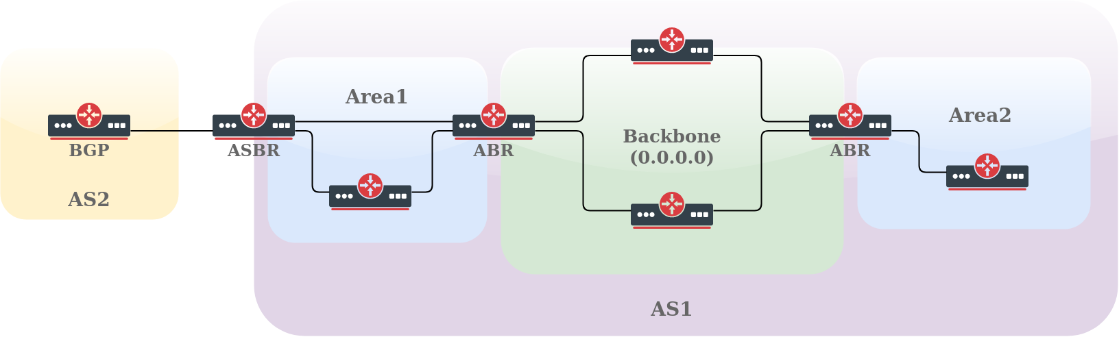
Each OSPF area has its own unique Area ID and the area with an Area ID of 0.0.0.0 (called the Backbone area) is the main one where any other area should connect. Routers that connect to more than one area are called ABR (Area Border Routers), their main responsibility is summarization and update suppression between connected areas. The router connecting to another routing domain is called ASBR (Autonomous System Boundary Router).
RouterOS area configuration is done in /routing/ospf/area menu. For example, configuration of ABR router with multiple attached areas, one Stub area and one default area:
| Code Block | ||
|---|---|---|
| ||
/routing ospf area
add name=backbone_v2 area-id=0.0.0.0 instance=v2inst
add name=stub_area area-id=1.1.1.1 instance=v2inst type=stub
add name=another_area area-id=2.2.2.2 instance=v2inst type=default |
OSPF can have 5 types of areas. Each area type defines what type of LSAs the area supports:
- standard/default - OSPF packets can normally be transmitted in this area, it supports type 1,2,3,4 and 5 LSAs
- backbone - as already mentioned this is the main area where any other area connects. It is basically the same as standard area but identified with ID 0.0.0.0
- stub - this area does not accept any external routes
- totally stubby - variation of stub area
- not-so-stubby (NSSA) - variation of stub area
Standard Area
Stub Area
Main purpose of stub areas is to keep such areas from carrying external routes. Routing from these areas to the outside world is based on a default route. Stub area reduces the database size inside an area and reduces memory requirements of routers in the area.
Stub area has few restrictions, ASBR routers cannot be internal to the area, stub area cannot be used as transit area for virtual links. The restrictions are made because stub area is mainly configured not to carry external routes.
Let's consider the example above. Area1 is configured as stub area meaning that routers R2 and R3 will not receive any routing information from backbone area except default route.
Totally Stubby Area
Totally stubby area is an extension for stub area. A totally stubby area blocks external routes and summarized (inter-area) routes from going into the area. Only intra-area routes are injected into the area. Totally stubby area is configured as stub area with additional no-summaries flag.
| Code Block | ||
|---|---|---|
| ||
/routing ospf area
add name=totally_stubby_area area-id=1.1.1.1 instance=v2inst type=stub no-summaries |
NSSA
Not-so-stubby area (NSSA) is useful when it is required to inject external routes, but injection of type 5 LSA routes is not required.
Look at the image above. There are two areas (backbone and area1) and RIP connection to area1. We need Area1 to be configured as stub area, but it is also required to inject external routes from RIP protocol. Area1 should be configured as NSSA in this case.
Configuration example does not cover RIP configuration.
| Note |
|---|
Virtual links cannot be used over NSSA areas. |
Virtual Link
Neighbour Relationship and Adjacency
...