CME Gateway (CME22-2n-BG77)
Safety Warnings
Before you work on any equipment, be aware of the hazards involved with electrical circuitry, and be familiar with standard practices for preventing accidents.
Ultimate disposal of this product should be handled according to all national laws and regulations.
The Installation of the equipment must comply with local and national electrical codes.
This unit is intended to be installed in the rackmount. Please read the mounting instructions carefully before beginning installation. Failure to use the correct hardware or to follow the correct procedures could result in a hazardous situation for people and damage to the system.
This product is intended to be installed indoors. Keep this product away from water, fire, humidity, or hot environments.
Use only the power supply and accessories approved by the manufacturer, and which can be found in the original packaging of this product.
Read the installation instructions before connecting the system to the power source.
We cannot guarantee that no accidents or damage will occur due to the improper use of the device. Please use this product with care and operate at your own risk!
In the case of device failure, please disconnect it from power. The fastest way to do so is by unplugging the power plug from the power outlet.
It is the customer's responsibility to follow local country regulations, including operation within legal frequency channels, output power, cabling requirements, and Dynamic Frequency Selection (DFS) requirements. All Mikrotik radio devices must be professionally installed.
Exposure to Radio Frequency Radiation: This MikroTik equipment complies with the FCC, IC, and European Union radiation exposure limits set forth for an uncontrolled environment. This MikroTik device should be installed and operated no closer than 20 centimeters from your body, occupational user, or the general public.
Connecting
Make sure your Internet service provider is allowing hardware change and will issue an automatic IP address.
Connect your ISP cable to the first Ethernet port or, if cellular CAT-M connection is required, open the bottom section and install the SIM card into the respective SIM slot;
- Connect the device to the power source;
- Open network connections on your computer, search for MikroTik wireless network and connect to it, or, connect your PC to the second Ethernet port;
- The configuration can to be done through the wireless network using a web browser or mobile app, or through the Ethernet connection using a web browser. Alternatively, you can use a WinBox configuration tool https://mt.lv/winbox;
- Open http://192.168.88.1 in your web browser to start configuration, user name: admin and there is no password by default (or, for some models, check user and wireless passwords on the sticker);
- Click the Check for updates button and update your RouterOS software to the latest version, must have an active Internet connection;
- In the Quick Set, choose your country and apply country regulation and wireless settings;
- Set up your wireless network password;
- Set up your router password.
Mounting and bottom lid
- The backside of the device has 2 holes, where you can input the metal ring.
- Unscrew the metal ring to loosen it, put one end of the metal ring into the hole and wrap the ring around the pole or a mast, then screw the metal ring to tighten it up - see. 1.
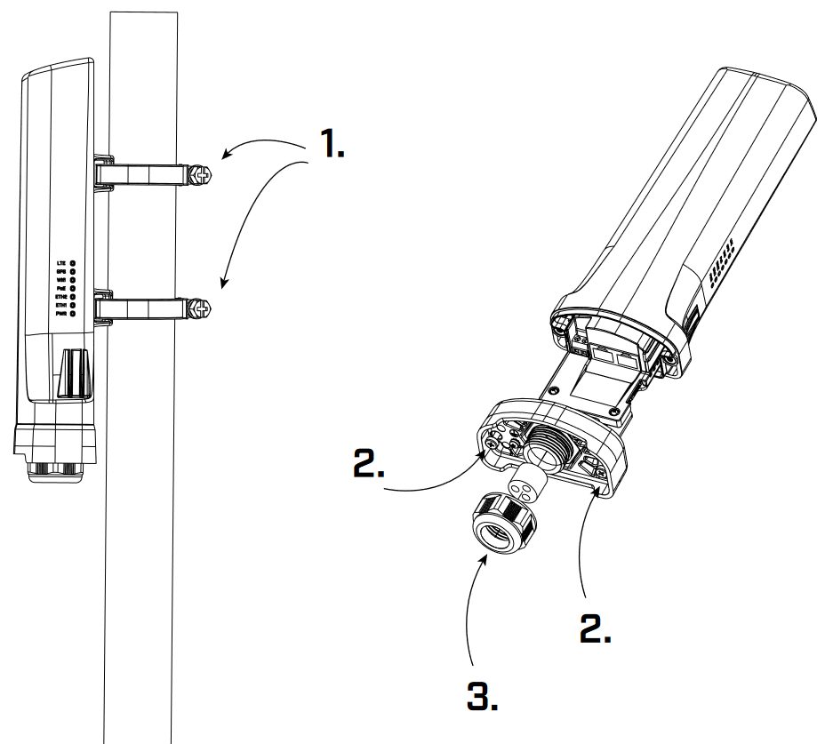
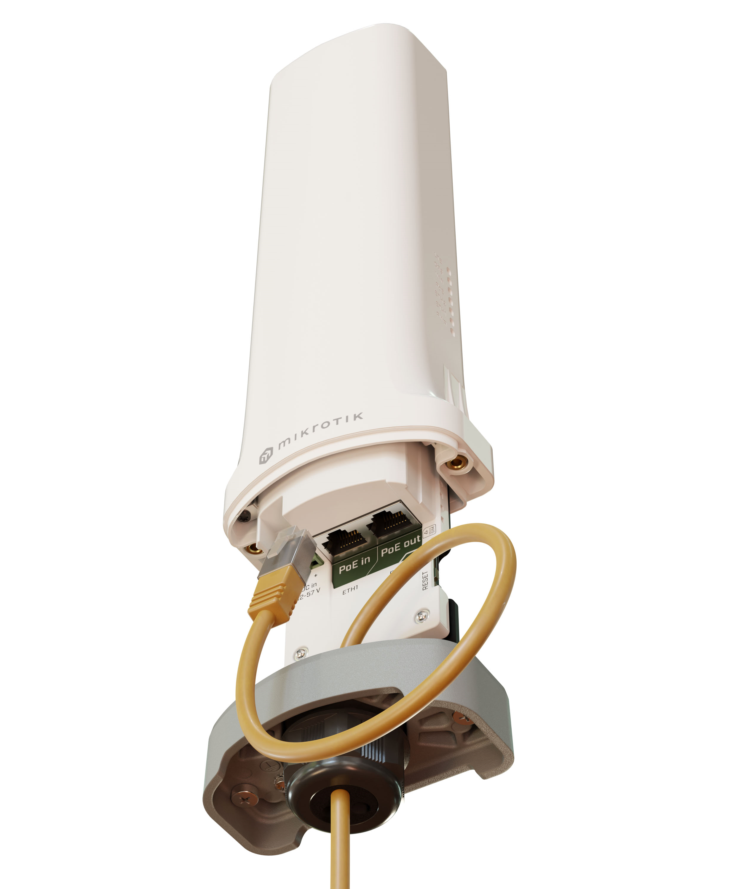
- Unscrew the two screws under the bottom lid. When they are loose, slightly pull down the bottom lid to open access to Ethernet ports, SIM slot and reset button - see. 2.
Powering
- Ethernet port accepts 802.3af/at Power over Ethernet 18-57 V DC.
- 2-pin terminal input Voltage 12-57 V DC.
The power consumption under maximum load with attachments can reach 31 W. Max power consumption without attachments 6W.
Connecting to a PoE Adapter:
- Connect the Ethernet cable from the device to the PoE+DATA port of the PoE adapter.
- Connect an Ethernet cable from your local network (LAN) to the PoE adapter.
- Connect the power cord to the adapter, and then plug the power cord into a power outlet.
Grounding
The grounding wire should be connected to the RouterBOARD grounding wire attachment point. This wire should then be connected to the base of the installation location, ensuring the connection meets grounding standards.
Configuration
Once logged in, we recommend clicking the "Check for updates" button in the QuickSet menu, as updating your RouterOS software to the latest version ensures the best performance and stability. For wireless models, please make sure you have selected the country where the device will be used, to conform to local regulations.
RouterOS includes many configuration options in addition to what is described in this document. We suggest starting here to get yourself accustomed to the possibilities: https://mt.lv/help. In case an IP connection is not available, the WinBox tool (https://mt.lv/winbox) can be used to connect to the MAC address of the device from the LAN side (all access is blocked from the Internet port by default).
For recovery purposes, it is possible to boot the device for reinstallation, see section Buttons and jumpers.
Extension slots and ports
- 2.4 GHz, 802.11b/g/n, antenna gain 2 dBi.
- Built-in GPS module (GPS, GLONASS, BeiDou, Galileo).
- Two 10/100 Ethernet ports, supporting automatic cross/straight cable correction (Auto MDI/X). Either straight or crossover cable can be used for connecting to other network devices. The Ethernet port accepts 18-57 V DC power from an 802.3af/at PoE injector.
- One nano SIM slot.
GPS and CAT-M
CME22-2n-BG77 supports CAT-M and GNSS. Both cannot be used together simultaneously.
An example of the configuration to automate the switch between the cellular and GNSS priority is shown below under the Cellular and GNSS priority switch automation section. Please also check the guide at - WWAN and GNSS priority automatization.
A port named "modem" is used for cellular connection (serial/PPP connection) and GNSS NMEA data:
/port print
Flags: I - INACTIVE
Columns: NAME, CHANNELS, BAUD-RATE
#  NAME   CHANNELS  BAUD-RATE
0  modem         4     115200
Default modem port channel assignment:
1 - GNSS NMEA output port;
2 - AT/modem port;
Cellular modem configuration
Unlike LTE devices, the BG77 modem by default does not provide a direct IP modem interface (LTE interface), but provides AT/modem serial port which is used for serial/PPP connection.
BG77 modem AT commands can be found using the link.
The device has a serial/PPP connection preset:
/interface ppp-client print
Flags: X - disabled; R - running
 0 R  name="ppp-out1" max-mtu=1500 max-mru=1500 mrru=disabled port=modem data-channel=2 info-channel=2 apn="internet"
      pin="" user="" password="" profile=default phone="" dial-command="ATDT" modem-init="AT+QGPSCFG="priority",1"
      null-modem=no dial-on-demand=yes add-default-route=yes default-route-distance=2 use-peer-dns=yes keepalive-timeout=30
      allow=pap,chap,mschap1,mschap2
For more details on serial/PPP connection please check the link.
GNSS configuration
You can find more information by checking the guide here.
BG77 modem shares the same receiver for IoT cellular connectivity and GNSS signal reception. The preferred service can be prioritized by using the modem-init string (configured under /interface ppp-client) and GNSS service init-string (configured under /system gps).
AT commands are:
AT+QGPSCFG="priority",0 → to prioritize GNSS;
AT+QGPSCFG="priority",1 → to prioritize cellular IoT connectivity;
AT+QGPSEND → to stop GNSS reception;
AT+QGPS=1 → to start GNSS reception.
Additionally, you can configure Supported GNSS Constellations with the help of the AT command:
AT+QGPSCFG="gnssconfig"[,<GNSS_config>]
,which takes effect only after the module is rebooted and where <GNSS_config> represents the Constellations themselves (can be "1" to "5"):
- 1 → GPS + GLONASS
- 2 → GPS + BeiDou
- 3 → GPS + Galileo
- 4 → GPS + QZSS
- 5 → Variable - one of the options (1–4) is selected based on MCC of the camped network
Cellular modem firmware upgrade
Please note that:
- DFOTA frimware check/upgrade can be done using any internet connection (including wi-fi and ethernet uplinks). As a result, the modem firmware can be upgraded for devices where BG77 does not have cellular connectivity, eg when its used as a GPS receiver only.
- Firmware upgrade is supported when BG77 modem serial/PPP interface is using the main AT/modem channel (data-channel=2).
To check currently installed BG77 firmware version, specify "upgrade=no" parameter using the command:
/interface/ppp-client/firmware-upgrade ppp-out1 upgrade=no
  installed: BG77LAR02A04_01.001.01.001
     latest: BG77LAR02A04_01.009.01.009
To update BG77 modem firmware, set the parameter "upgrade=yes":
/interface/ppp-client/firmware-upgrade ppp-out1 upgrade=yes
Cellular and GNSS priority switch automation
Automation can be achieved using ppp profile "on-down" script, "idle-timeout" features and PPP interface "dial on demand" setting.
When implemented, BG77 modem will use cellular data when there is internet traffic present (during this time GNSS coordinates are not received), and will automatically enable GPS reception when there is no internet traffic detected.
Idle-timeout parameter specifies the amount of time after which the link will be terminated if there is no activity present.
On-down script field allows you to configure a script that will be run every time the PPP interface goes down (including after idle-timeout inactivity). The script will set modem's priority to GNSS reception.
Dial-on-demand will make sure that PPP interface tries to establish the connection only when there is outgoing traffic present (additionally, the modem will automatically set WWAN/cellular connection priority). This will make sure that after idle-timeout occurs, the connection is not automatically reestablished unless outgoing packets are detected.
By combining the three features, you can achieve the scenario, where:
- If you have outgoing traffic, PPP interface is going to be up (because of the "dial on demand") and the priority will be set to the cellular connection. PPP interface's modem initialization AT command (that is configured under PPP interface's
modem-init="AT+QGPSCFG="priority",1"setting) for WWAN priority is sent. During this time, GPS coordinates will not be received. - If no traffic is detected after "idle-timeout" inactivity window, the PPP interface will go down and, because of the "dial on demand" setting, it will not establish the connection until outgoing packets are detected. This is where "on-down" script is run that switches WWAN priority to GNSS priority.
In order to implement it, simply add a new PPP profile:
/ppp profile add idle-timeout=30s name=BG77 on-down="/interface ppp-client at-chat [find where modem-init=\"AT+QGPSCFG=\\\"priority\\\",1\"] input=\"AT+QGPSCFG=\\\"priority\\\",0\""
The example above, creates a new profile with the name "BG77", sets idle-timeout to 30 seconds, and enables the on-down script that will send GNSS priority AT command.
After that, make sure to apply this newly created profile onto the PPP interface:
/interface ppp-client set [find] profile=BG77
And confirm that it was applied (profile=BG77):
/interface ppp-client print
Flags: X - disabled; R - running
0 R name="ppp-out1" max-mtu=1500 max-mru=1500 mrru=disabled port=modem data-channel=2 info-channel=2
apn="internet" pin="" user="" password="" profile=BG77 phone="" dial-command="ATDT"
modem-init="AT+QGPSCFG="priority",1" null-modem=no dial-on-demand=yes add-default-route=yes
default-route-distance=1 use-peer-dns=yes keepalive-timeout=30 allow=pap,chap,mschap1,mschap2
Buttons and jumpers
Reset button
- Hold this button during boot time until the LED light starts flashing, release the button to reset RouterOS configuration (total 5 seconds).
- Keep holding for 5 more seconds, LED turns solid, release now to turn on CAP mode. The device will now look for a CAPsMAN server (total 10 seconds).
- Or keep holding the button for 5 more seconds until LED turns off, then release it to make the RouterBOARD look for Netinstall servers (total 15 seconds).
Regardless of the above option used, the system will load the backup RouterBOOT loader if the button is pressed before power is applied to the device. Useful for RouterBOOT debugging and recovery.
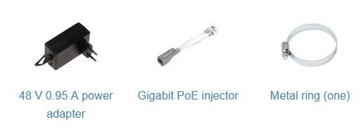
Accessories
The package includes the following accessories that come with the device:
Operating system support
The device supports RouterOS software version v7. The specific factory-installed version number is indicated in the RouterOS menu /system resource. Other operating systems have not been tested.
To avoid pollution of the environment, please separate the device from household waste and dispose of it in a safe manner, such as at designated waste disposal sites. Familiarize yourself with the procedures for the proper transportation of the equipment to the designated disposal sites in your area.