Summary
IP Multicast is a technology that allows data to be efficiently shared with many recipients over the Internet. Senders transmit their data to a specific multicast IP address, and receivers indicate their interest in receiving data sent to that address. The network then takes care of delivering the data from senders to receivers.
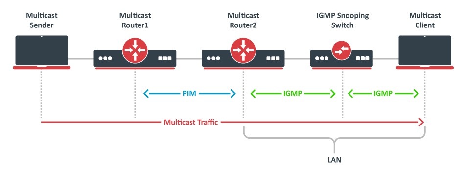
If both the sender and receiver for a multicast group are on the same local network segment, routers are not required for the process. Communication can happen directly, and this can be enhanced with the use of IGMP snooping switches. However, if the sender and receiver are on different network segments, a multicast routing protocol must be used to establish the path for data transmission between them.
Protocol Independent Multicast - Sparse Mode (PIM-SM or PIM) enables RouterOS to support multicast streaming over the network area. PIM stands for Platform Independent Multicast, meaning it's not tied to any particular unicast routing. SM stands for Sparse-Mode, which means that specific control messages ensure that data is delivered only to network segments where there are receivers that want it. In addition to the routing protocols that manage data transmission between network segments, routers need a way to discover local receivers on their directly connected network segment. For IPv4, this is achieved through the Internet Group Management Protocol (IGMP), and Multicast Listener Discovery (MLD) for IPv6.
RouterOS v7 has PIM-SM configuration available in the main system package. Older RouterOS versions need an additional multicast package installed in order to use PIM-SM. See more details about Packages.
The feature is not supported on SMIPS devices (hAP lite, hAP lite TC and hAP mini).
Basic multicast routing on single device
Picture this scenario, you have got a router with two interfaces, namely ether1 and ether2, and each of them is set up in separate networks. Normally, the router will create connected routes and hosts on both networks will be able to communicate using unicast traffic. However, if you want to enable multicast communication between these networks, you'll need to configure multicast routing separately because it won't work otherwise. In this scenario, we are going to create a simple configuration. This involves creating a PIM instance and configuring the required interfaces.
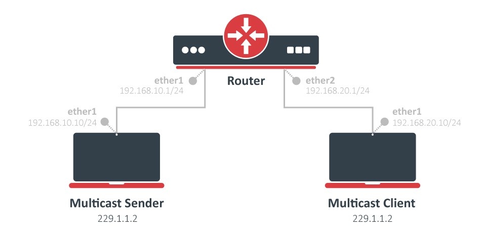
Begin by ensuring that IP addresses are set up on the router's interfaces.
/ip address
add address=192.168.10.1/24 interface=ether1 network=192.168.10.0
add address=192.168.20.1/24 interface=ether2 network=192.168.20.0
Configure PIM instance. For this example, the default settings should work fine.
/routing pimsm instance
add name=pimsm-instance-1
Last, add interfaces and specify the PIM instance you created earlier.
/routing pimsm interface-template
add interfaces=ether1,ether2 instance=pimsm-instance-1
Now router starts listening to IGMP membership reports (client join messages) and will route multicast traffic to clients interested in receiving it.
To test the configuration, you can configure a multicast sender using RouterOS traffic-generator and IGMP client using GMP.
# Multicast Sender
/ip address
add address=192.168.10.10/24 interface=ether1 network=192.168.10.0
/tool traffic-generator packet-template
add interface=ether1 ip-dst=229.1.1.2 mac-dst=01:00:5E:01:01:02/FF:FF:FF:FF:FF:FF name=multicast
/tool traffic-generator quick tx-template=multicast mbps=10

# Multicast Client
/ip address
add address=192.168.20.10/24 interface=ether1 network=192.168.20.0
/routing gmp
add disabled=no groups=229.1.1.2 interfaces=ether1
To verify whether multicast traffic is being properly routed, monitor the received packet counters on the client interface or use tools like Torch or a Packet Sniffer.
It is also possible to monitor active multicast group on router:
/routing pimsm uib-g print
Columns: INSTANCE, GROUP
# INSTANCE          GROUP
0 pimsm-instance-1  229.1.1.2

/routing pimsm uib-sg print
Flags: K - KEEPALIVE; S - SPT-BIT
Columns: INSTANCE, GROUP, SOURCE
#    INSTANCE          GROUP      SOURCE
0 KS pimsm-instance-1  229.1.1.2  192.168.10.10
Multicast routing with static RP
In the upcoming example, we'll be working with multiple PIM routers, as shown in the diagram below. PIM-SM uses shared trees and to make this work, we need to designate a specific node as the multicast root distribution point. In PIM, this router is called the Rendezvous Point, or RP. There are various methods for selecting an RP in PIM, such as the Bootstrap Router (BSR) method. However, for this example, we'll be using a straightforward approach known as static RP configuration. This means that the administrator can manually specify one or more RPs for specific multicast groups.
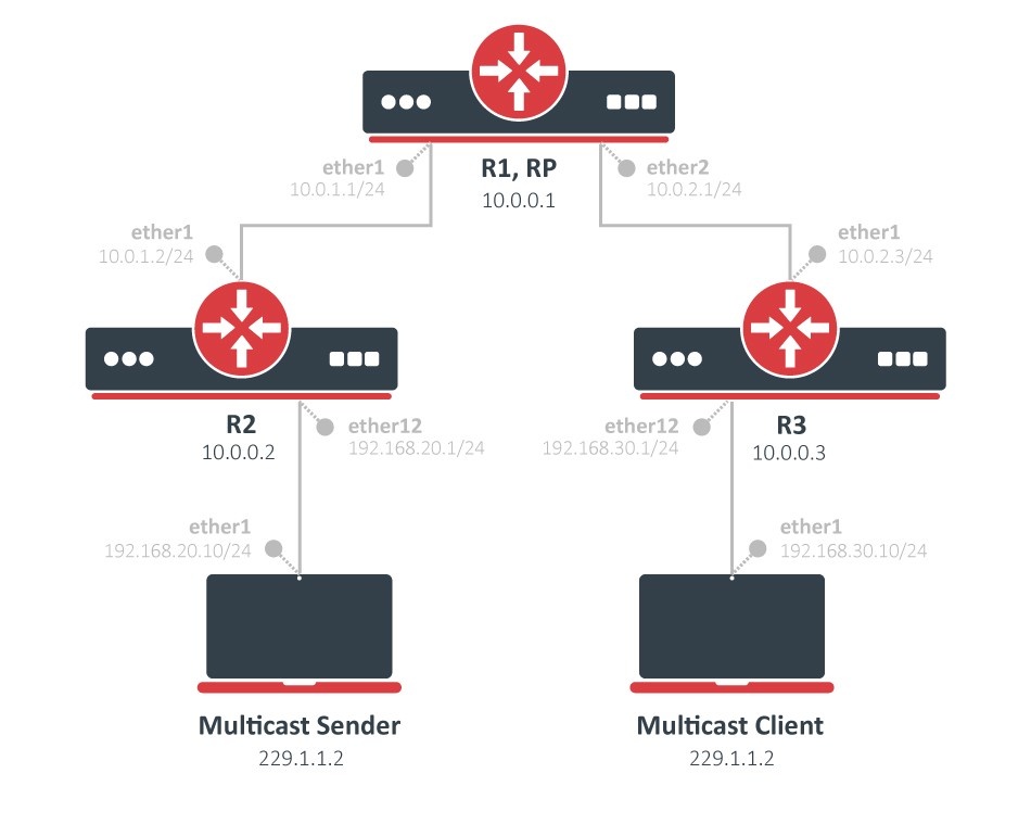
To get started, we'll need to configure IP addresses and set up unicast routing. In this example, we'll use OSPF to exchange routing information between the routers. See more details about OSFP.
# R1 Rendezvous Point:
/interface bridge
add name=loopback
/ip address
add address=10.0.0.1 interface=loopback network=10.0.0.1
add address=10.0.1.1/24 interface=ether2 network=10.0.1.0
add address=10.0.2.1/24 interface=ether3 network=10.0.2.0
/routing ospf instance
add disabled=no name=ospf-instance-1 router-id=10.0.0.1
/routing ospf area
add disabled=no instance=ospf-instance-1 name=ospf-area-1
/routing ospf interface-template
add area=ospf-area-1 disabled=no interfaces=loopback,ether2,ether3

# R2:
/interface bridge
add name=loopback
/ip address
add address=10.0.0.2 interface=loopback network=10.0.0.2
add address=10.0.1.2/24 interface=ether1 network=10.0.1.0
add address=192.168.20.1/24 interface=ether12 network=192.168.20.0
/routing ospf instance
add disabled=no name=ospf-instance-1 router-id=10.0.0.2
/routing ospf area
add disabled=no instance=ospf-instance-1 name=ospf-area-1
/routing ospf interface-template
add area=ospf-area-1 disabled=no interfaces=loopback,ether1,ether12

# R3:
/interface bridge
add name=loopback
/ip address
add address=10.0.0.3 interface=loopback network=10.0.0.3
add address=10.0.2.3/24 interface=ether1 network=10.0.2.0
add address=192.168.30.1/24 interface=ether12 network=192.168.30.0
/routing ospf instance
add disabled=no name=ospf-instance-1 router-id=10.0.0.3
/routing ospf area
add disabled=no instance=ospf-instance-1 name=ospf-area-1
/routing ospf interface-template
add area=ospf-area-1 disabled=no interfaces=loopback,ether1,ether12
As in the previous example with a single router, we need to configure the PIM instance and add the necessary interfaces on all routers.
# R1 Rendezvous Point:
/routing pimsm instance
add disabled=no name=pimsm-instance-1
/routing pimsm interface-template
add instance=pimsm-instance-1 interfaces=loopback,ether2,ether3

# R2:
/routing pimsm instance
add disabled=no name=pimsm-instance-1
/routing pimsm interface-template
add instance=pimsm-instance-1 interfaces=loopback,ether1,ether12

# R3:
/routing pimsm instance
add name=pimsm-instance-1
/routing pimsm interface-template
add instance=pimsm-instance-1 interfaces=loopback,ether1,ether12
Now, let's take a look at our PIM neighbors and their current statuses. On R1, there are two neighbors, while on R2 and R3, there's only one neighbor each.
# R1 Rendezvous Point:
/routing pimsm neighbor print
Flags: R - DESIGNATED-ROUTER; J - JOIN-TRACKING
Columns: INSTANCE, ADDRESS, PRIORITY
#    INSTANCE          ADDRESS          PRIORITY
0 RJ pimsm-instance-1  10.0.1.2%ether2  1
1 RJ pimsm-instance-1  10.0.2.3%ether3  1

# R2:
/routing pimsm neighbor print
Flags: R - DESIGNATED-ROUTER; J - JOIN-TRACKING
Columns: INSTANCE, ADDRESS, PRIORITY
#    INSTANCE          ADDRESS          PRIORITY
0  J pimsm-instance-1  10.0.1.1%ether1  1

# R3:
/routing pimsm neighbor print
Flags: J - JOIN-TRACKING
Columns: INSTANCE, ADDRESS, PRIORITY
#   INSTANCE          ADDRESS          PRIORITY
0 J pimsm-instance-1  10.0.2.1%ether1  1
Finally, we will select one router to act as our Rendezvous Point (RP). We will configure the R1 loopback IP address on all PIM routers. It's important to ensure that each router has the correct routing information to reach the R1 loopback address.
# R1 Rendezvous Point:
/routing pimsm static-rp
add address=10.0.0.1 instance=pimsm-instance-1

# R2:
/routing pimsm static-rp
add address=10.0.0.1 instance=pimsm-instance-1

# R3:
/routing pimsm static-rp
add address=10.0.0.1 instance=pimsm-instance-1