...
- Make sure your ISP is allowing hardware change and will issue an automatic IP address.
- Open the bottom lid (see "Bottom Lid").
- Connect an external antenna to the SMA connector (see "Antenna usage").
- Connect the device to the power source (see "Powering").
- Connect with your device to the MikroTik wireless network
- The configuration has to be done through the wireless network using a web browser or mobile app - (see "MikroTik mobile app"). Alternatively, you can use the WinBox configuration tool https://mt.lv/winbox. By default, Ethernet port access is blocked by a firewall.
- Once connected to the wireless network, open https://192.168.88.1
 in your web browser to start the configuration.
 - user name: admin and there is no password by default (or, for some models, check user and wireless passwords on the sticker).
- When using a mobile application choose Quick setup and it will guide you through all necessary configurations in six easy steps.
- Find your LR Gateway ID on the label within the product and register it in your Network Server.
- To make the device connect to the LR Network Server, please see "Configuration".
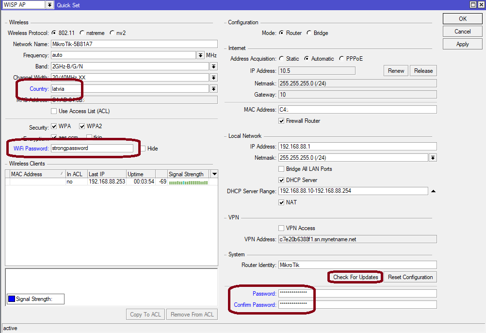
- Click the "Check for updates" button and update your RouterOS software to the latest version, the device needs to have an active Internet connection.
- After the update set your country, to apply country regulation settings.
- Set your WiFi password.
- Set the router password.
- The following RouterOS "npk" packages are required for the core functionality of the product: lora, system.
Expansion slots and ports
- 10/100 Ethernet port, supporting automatic cross/straight cable correction (Auto MDI/X). Either straight or crossover cable can be used for connecting to other network devices.
- External SMA antenna connector is already connected to the LR card.
- Automotive connector. Pinout: A - reserved for future use (orange), B - reserved for future use (blue), C - ground (black), D – power in (red).
...
We recommend using an external antenna, the "TOF-2400-8V-4" - which can be obtained separately. The antenna kit has a pole mount and cable ready to use with LR cards. https://mikrotik.com/product/tof_2400_8v_4
SMA connector located under the bottom door is already connected to the LR card and ready to be used. Please see the Mounting section on how to remove the door.
| Info |
|---|
Please connect and disconnect the antenna, when the device is turned off! |
Internal antenna 4.7dBi can be used for setups where the distance to the gateway is closer than 1km. By default, the antenna is not connected to the card! To use an internal antenna:
- Open bottom door (see "Mounting").
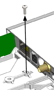
- Use the PH2 screwdriver to remove the screw.
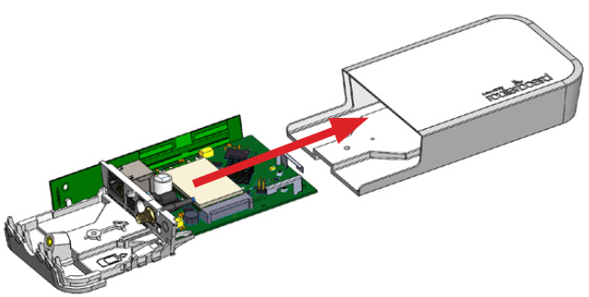
- Disassemble the upper case from the bottom by sliding them to opposite sides.
- Locate the internal antenna cable and replace it with the SMA cable connector on the LR card.
...
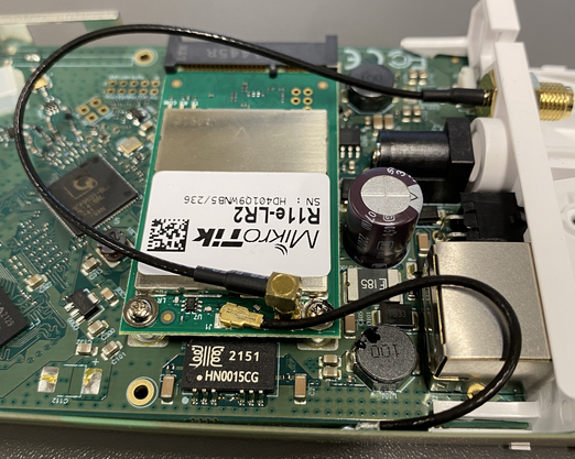
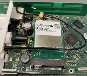
There is no need to disasemble the device. The installed LR2 mini PCIe card has two connectors available - uFL and MMCX. The internal antenna is attached via a uFL connecter and is ready to be used from the get-go. MMCX connector is already attached to the SMA and if you wish to use an external antenna, just connect it to the SMA. The device will choose which antenna to use based on the setting that will be shown later. Please connect and disconnect the antenna, when the device is turned off! |
Internal antenna 4.7dBi can be used for setups, where the distance between the node and the device is up to 200 meters (the actual distance needs to be checked in the environment). This antenna is attached and ready to be used.
To confirm how the antennas are attached:
- Open the bottom door (see "Mounting").
- Use the PH2 screwdriver to remove the screw.
- Disassemble the upper case from the bottom by sliding them to opposite sides.
- An internal antenna will use the uFL connector and SMA (for the external antenna) will be connected via the MMCX connector as per the pictures below.
- Reassembly.
The software is responsible for selecting the antenna used by the device.
Make sure that the right connector is used by the module in the software settings.
In order to do that, go to the device's GUI and check which connector is used under LoRa → Devices → "Double-click" on the gateway → Under the "Antenna" section:
![]()
Buttons and jumpers
The reset button has three functions:
...