...
This example uses static WDS links that are dynamically added as mesh ports when they become active. Two different frequencies are used: one for AP interconnections, and one for client connections to APs, so the AP must have at least two wireless interfaces. Of course, the same frequency for all connections also could be used, but that might not work as good well because of potential interference issues.
...
Here WDS interface is added manually , because static WDS mode is used. If you are using wds-mode=dynamic-mesh, all WDS interfaces will be created automatically. The frequency and band parameters are specified here only to produce valid example configuration; mesh protocol operations is are by no means limited to , or optimized for, these particular values.
| Note |
|---|
...
You may want to increase |
...
the disconnect-timeout wireless interface option to make the protocol more stable. |
In real-world setups you also should take care of securing the wireless connections, using /interface wireless security-profile. For simplicity, that configuration is not shown here.
...
The FDB (Forwarding Database) at the moment contains information only about local MAC addresses, non-mesh nodes reachable through a local interface, and direct mesh neighbors:
...
| Code Block | ||
|---|---|---|
| ||
[admin@A] > /ping 00:0C:42:00:00:CC 00:0C:42:00:00:CC 64 byte ping time=108 ms 00:0C:42:00:00:CC 64 byte ping time=51 ms 00:0C:42:00:00:CC 64 byte ping time=39 ms 00:0C:42:00:00:CC 64 byte ping time=43 ms 4 packets transmitted, 4 packets received, 0% packet loss round-trip min/avg/max = 39/60.2/108 ms |
Router A had to discover a path to Router C first, hence the slightly larger time for the first ping. Now the FDB also contains an entry for 00:0C:42:00:00:CC, with type "mesh".
Also, test that ARP resolving works and so does IP level ping:
...
Mesh traceroute
There is also a mesh traceroute command, that can help you to determine which paths are used for routing.
...
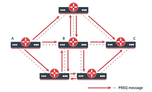
Router A wants to discover a path to C
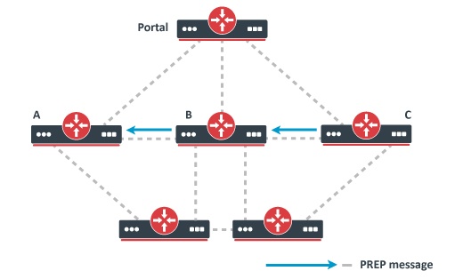
Router C sends a unicast response to A
In reactive mode, HWMP+ is very much like AODV (Ad-hoc On-demand Distance Vector). All paths are discovered on-demand, by flooding Path Request (PREQ) message in the network. The destination node or some router that has a path to the destination will reply with a Path Response (PREP). Note that if the destination address belongs to a client, the AP this client is connected to will serve as a proxy for him (i.e. reply to PREQs on his behalf).
...
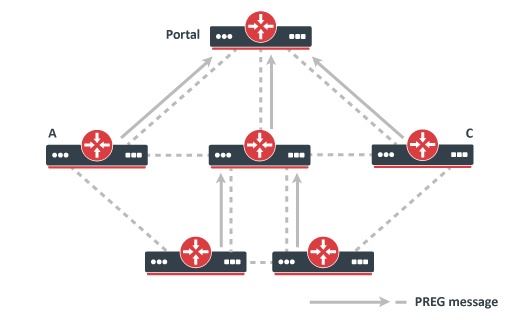
Internal nodes respond with PREGs
In proactive mode, there are some routers configured as portals. In general, being a portal means that the router has interfaces to some other network, , i.e. it is an entry/exit point to the mesh network.
The portals will announce their presence by flooding the Root Announcement (RANN) message in the network. Internal nodes will reply with a Path Registration (PREG) message. The result of this process will be routing trees with roots in the portal.
Routes to portals will serve as a kind of default route. If an internal router does not know the path to a particular destination, it will forward all data to its closest portal. The portal will then discover the path on behalf of the router , if needed. The data afterwards afterward will flow through the portal. This may lead to sub-optimal routing , unless the data is addressed to the portal itself or some external network the portals has have interfaces to.
Proactive A proactive mode is best suited when most of the traffic goes between internal mesh nodes and a few portal nodes.
Topology change detection
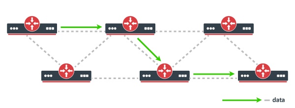
Data flow path
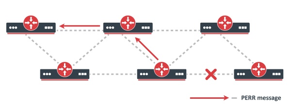
After the link disappears, an error is propagated upstream
HWMP+ uses Path Error (PERR) message to notify that a link has disappeared. The message is propagated to all upstream nodes up to the data source. The source on PERR reception restarts the path discovery process.
FAQ
...
Q. How the route selection is done?
A. The route with the best metric is always selected after the discovery process. There is also a configuration option to periodically reoptimize already known routes.
...
- For Ethernet links the metric is configured statically (same as for OSPF, for example).
- For WDS links the metric is updated dynamically depending on actual link bandwidth, which in turn is influenced by wireless signal strength, and the selected data transfer rate.
Currently, the protocol does not take in into account the amount of bandwidth being used on a link, but that might be also used in the future.
Q. How is this better than OSPF/RIP/layer-3 routing in general?
A. WDS networks usually are bridged, not routed. The ability to self-configure is important for mesh networks; , and routing generally requires much more configuration than bridging. Of course, you can always run any L3 routing protocol over a bridged network, but for mesh networks that usually makes little sense. Note: Since
| Note |
|---|
Since optimized layer-2 multicast forwarding is not included in the mesh protocol, it is better to avoid forwarding any multicast traffic (including OSPF) over meshed networks. If you need OSPF, then you have to |
...
configure OSPF NBMA |
...
neighbors that |
...
use unicast mode instead. |
Q. What about performance/CPU requirements?
A. The protocol itself, when properly configured, will take much less fewer resources than OSPF (for example) would. Data forwarding performance on an individual router should be close to that of bridging.
...
A. The internal structure of a an RSTP network is transparent to the mesh protocol (because mesh hello packets are forwarded inside the RSTP network). The mesh will see the path between two entry points in the RSTP network as a single segment. On the other hand, a mesh network is not transparent to the RSTP, since RSTP hello packets are not be forwarded inside the mesh network. (This is the behaviour behavior since v3.26)
| Warning |
|---|
...
Routing loops are possible |
...
if a mesh network is attached to |
...
an RSTP network in two or more points! |
Note that if you have a WDS link between two access points, then both ends must have the same configuration (either as ports in a mesh on both ends , or as ports in a bridge interface on both ends).
You can also put a bridge interface as a mesh port (to be able to use a bridge firewall, for example).
...
A. If the entry/exit points are configured as portals (i.e. proactive mode is used), each router inside the mesh network will select its closest portal and forward all data to it. The portal will then discover a path on behalf of the router , if needed.
Q. How to control or filter mesh traffic?
A. At the moment the only way is to use a bridge firewall. Create a bridge interface, put the WDS interfaces and/or Ethernets in that bridge, and put that bridge in a mesh interface. Then configure bridge firewall rules.
To match MAC protocol used for mesh traffic encapsulation, use MAC protocol number 0x9AAA, and to match mesh routing traffic, use MAC protocol number 0x9AAB. Example:
| Code Block | ||
|---|---|---|
| ||
interface bridge settings set use-ip-firewall=yes interface bridge filter add chain=input action=log mac-protocol=0x9aaa interface bridge filter add chain=input action=log mac-protocol=0x9aab |
...
| Note |
|---|
It |
...
is perfectly possible to create mixed mesh/bridge setups that will not work (e.g. Problematic example 1 with bridge instead of a switch). The recommended fail-safe way that will always work is to create a separate bridge interface per each of the physical interfaces; then add all these bridge interfaces as mesh ports. |
Advanced topics
We all know that it's easy to make problematic layer-2 bridging or routing setups and it can be hard to debug them. (Compared to layer-3 routing setups.) So here are a few bad configuration examples which that could create problems for you. Avoid them!
...
Consider what happens when router A wants to send something to C. We suppose router A either knowns knows or floods data to all interfaces. Either way, data arrives at the switch. The switch, not knowing anything about the destination's MAC address, forwards the data to both B and D.
...
- B receives the packet on a mesh interface. Since the MAC address is not local for B and B knows that he is not the designated router for the Ethernet network, he simply ignores the packet.
- D receives the packet on a mesh interface. Since the MAC address is not local for B and D is the designated router for the Ethernet network, he initiates the path discovery process to C.
After path discovery is completed, D has information that C is reachable over B. Now D encapsulates the packet and forwards it back to the Ethernet network. The encapsulated packet is forwarded by the switch, received and forwarded by B, and received by C. So far everything is good.
...
In contrast, if B took up the role of a designated router, everything would be OK, because traffic would not have to go through the Ethernet switch twice.
...
It is not possible to bridge wlan1 and wlan2 on router B now. The reason for this is pretty obvious if you understand how WDS works. For WDS communications four address frames are used. This is because for wireless multihop forwarding you need to know both the addresses of the intermediate hops, as well as the original sender and final receiver. In contrast, non-WDS 802.11 communication includes only three MAC addresses in a frame. That's why it's not possible to do multihop multi-hop forwarding in station mode.
...
- If you want router C to act as a repeater either for wireless or Ethernet traffic, configure the WDS link between router B and router C, and run mesh routing protocol on all nodes.
- In other cases configure wlan2 on router B in AP mode and wlan WLAN on router C in station mode.
...