...
- Unscrew two screws and remove doors to access all ports. Please see the 16351316 Mounting section.
- Connect your Internet cable to the Ethernet port (this is optional if using LTE as the primary connection).
- Install your modem see miniPCIe slot usage (optional).
- Insert the SIM card into the slot (optional) (see SIM card).
- Connect GPS antenna (optional).
- Mount unit in your desired place, please see 16351316 Mounting paragraph.
- Choose your powering solution, please see the 16351316 Powering section for possibilities.
- Set your computer IP configuration to automatic (DHCP).
- From your PC or smartphone, connect to the wireless network name which starts with "MikroTik".
- Once connected to the wireless network, open https://192.168.88.1
 in your web browser to start configuration, since there is no password by default, you will be logged in automatically.
 - We recommend clicking the "Check for updates" button and updating your RouterOS software to the latest version to ensure the best performance and stability.
- Choose your country, to apply country regulation settings, and set up your password on the screen that loads.
...
- Built-in 2 GHz wireless access point module, AP/station/bridge/p2p modes are supported. Onboard PIF antennas built-in, as well as MMCX connectors for external antennas (software selectable).
- Two miniPCIe slots and three SIM slots.
- Built-in GPS module with an external SMA connector. Supports - GPS, GLONASS, BeiDou, Galileo).
- Gigabit Ethernet port, supporting automatic cross/straight cable correction (Auto MDI/X). Either straight or crossover cable can be used for connecting to other network devices. The Ethernet port accepts 12-30 V DC powering from a passive PoE injector.
- One DB9 RS232 serial port for serial console access. Configured as 115200 bit/s, 8 data bits, 1 stop bit, no parity.
- One USB 2.0 port for storage devices or cellular modems.
...
We recommend clicking the "Check for updates" button and updating your RouterOS software to the latest version to ensure the best performance and stability. RouterOS includes many configuration options in addition to what is described in this document. We suggest starting here to get yourself accustomed to the possibilities: https://mt.lv/help. In case IP connection is not available, the Winbox tool (https://mt.lv/winbox) can be used to connect to the MAC address of the device from the LAN side (all access is blocked from the internet port by default). For recovery purposes, it is possible to boot the device from a network, see the section 16351316 Reset button.
GPS
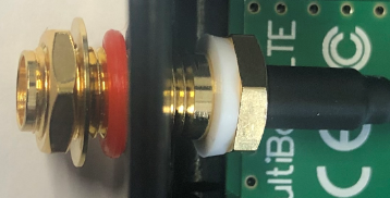
The built-in GPS module requires an external antenna to be used (SMA connector is already mounted behind the unit door). Please see the 16351316 Mounting section on how to remove the door.
Attention the GPS uses an active antenna, only connect and disconnect the antenna, when the device is turned off!
Supports - GPS, GLONASS, BeiDou, Galileo).
Make sure that the GPS package is installed on your device. Check by following command /system package print. If not installed please download extra packages at our download page accordingly to your RouterOS version and install GPS package by dragging it to the Files menu. Enable GPS and start working:
...
- MiniPCIe 1 (top slot) supports PCIe and USB 2.0 cards but is shared with the USB 2.0 type A port (can use either the USB port or miniPCIe slot at the same time). It can be used only for SIM slot #1.
- MiniPCIe 2 (bottom slot) supports only USB (2.0 and 3.0) miniPCIe modems (no PCIe support). Uses SIM slot #2 and SIM slot #3. By default uses SIM slot #2.
- USB 2.0 type A port (can only be used if miniPCIe 1 is not used).
- To use the top miniPCIe slot with a USB type miniPCIe card, switch the USB connections to the miniPCIe slot: /system routerboard usb set type=mini-PCIe This will disable the USB 2.0 port on the front of the unit.
- Insert the SIM card into the top slot by a chip on the SIM card facing down. Bottom slots – with the chip facing up.
...
This LtAP version is without a modem installed. In this case, an internal antenna is not connected.
Installing a miniPCIe module should be done by a qualified person, please follow safety precautions when handling electrical equipment, the device supports two LR cards:
- Use a wrist grounding strap when unpacking and working with electrical components to avoid electrical discharge (ESD) damage;
- Remove six screws on the bottom of the case and lift off the top part of the case.
- Locate the miniPCIe slot and remove two factory attached screws;
- Attach provided a thick thermal pad to the card, and install the card into miniPCIe slot so that thermal pad is between PCB and card;
- The secure card in place using previously removed two screws;
- Connect internal antenna cables to your modem. Or guide your antenna cables through openings near the GPS connector and connect to the modem. Recommended using silicone rubber to secure connectors in place.
- Attach a thinner thermal pad to the top of the card;
- When using external antennas, connectors can be attached on the case sides, to make openings use a 6.5 mm drill bit, please see 16351316 Mounting section part 4;
- Please see the picture below for reference on how to place rubber seals for best water protection;
- Reassembly in backorder. Tightening torque for PCB screws 0.3 Nm, case cover/enclosure screws 0.5 Nm.
...
For more information about this product, specifications, pictures, downloads, and test results please visit our web page: https://mikrotik.com/product/ltap
...
- Scan QR code and choose your preferred OS.
- Install and open application.
- By default, the IP address and user name will be already entered.
- Click Connect to establish a connection to your device through a wireless network.
- Choose Quick setup and the application will guide you through all basic configuration settings in a couple of easy steps.
- An advanced menu is available to fully configure all necessary settings.
...
Federal Communication Commission Interference Statement FCC ID: TV7LTAP2HND
This equipment has been tested and found to comply with the limits for a Class B digital device, pursuant to Part 15 of the FCC Rules. These limits are designed to provide reasonable protection against harmful interference in a residential installation.
This equipment generates, uses, and can radiate radio frequency energy and, if not installed and used in accordance with the instructions, may cause harmful interference to radio communications. However, there is no guarantee that interference will not occur in a particular installation. If this equipment does cause harmful interference to radio or television reception, which can be determined by turning the equipment off and on, the user is encouraged to try to correct the interference by one of the following measures:
...
IC:7442A-LTAP2HND
This device complies with Industry Canada's licencelicense-exempt RSS standard(s). Operation is subject to the following two conditions: (1) this device may not cause interference, and (2) this device must accept any interference, including interference that may cause undesired operation of the device.
Le présent appareil est conforme aux CNR d'Industrie Canada applicables aux appareils radio exempts de licence. L'exploitation est autorisée aux deux conditions suivantes: (1) l'appareil ne doit pas produire de brouillage, et (2) l'utilisateur de l'appareil doit accepter tout brouillage radioélectrique subi, même si le brouillage est susceptible d'en compromettre le fonctionnement.
IMPORTANT: Exposure to Radio Frequency Radiation.
This equipment complies with the IC radiation exposure limits set forth for an uncontrolled environment. This equipment should be installed and operated with a minimum distance of 30 cm between the radiator and any part of your body.
CAN ICES-3 (B)/NMB-3(B)
...