LtAP mini LTE series user manual for models:
LtAP mini LTE kit
LtAP mini LTE kit-US
LtAP mini 4G kit
The LtAP mini LTE kit is a wireless access point with two SIM card slots. The LtAP mini LTE, 4G kit comes with factory-installed a LTE card.
Connecting
- If the intent is to use GPS, an external antenna is required (see "GPS usageLtAP mini-series").
- Choose your powering solution (see "PoweringLtAP mini-series").
- Connect your Internet cable to the Ethernet port.
- Set your computer IP configuration to automatic (DHCP).
- Connect your direct input power jack if not using PoE, to start up the device.
- The device will boot up and Wireless network will be available for connecting.
- Open network connections on your PC, mobile phone or other device and search for MikroTik wireless network and connect to it.
- Once connected to the wireless network, open https://192.168.88.1

 in your web browser to start configuration, since there is no password by default, you will be logged in automatically. The configuration also can be done using the mobile app (see "MikroTik mobile appLtAP mini-series"), and WinBox configuration tool https://mt.lv/winbox.
 - We recommend clicking the "Check for updates" button and updating your RouterOS software to the latest version to ensure the best performance and stability.
- Choose your country, to apply country regulation settings and set up your password in on the screen that loads.
Mounting
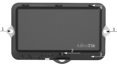
- It is possible to attach the device to a wall, using the provided screw holes on the sides of the unit. The device should be mounted in a way that the cable openings are pointing downward as shown in the picture.
- The ports are protected with a small door, that is held in place with one screw. Use the Philips PH2 screwdriver to access the ports.
- The door has cut-out places for all available ports, but please only break out the openings that you will use. The device can be used both indoors and outdoors. The IP rating scale for this device is IP54.
- The device enclosure has places where you can drill openings for external LTE and GPS antennas. Use a drill to make holes that are appropriate for the antenna cable used.
Alternatively, you can obtain a "DINrail Pro" - mounting bracket, designed to fit standard 35 mm x 7.5 mm DIN rails. https://mikrotik.com/product/dinrail_pro
When mounting outdoors, please ensure that any cable openings is are directed downwards. Use PoE injector and proper grounding. Recommended using Cat6 cable.
Warning! This equipment should be installed and operated with a minimum distance of 20 cm between the device and your body. Operation of this equipment in the residential environment could cause radio interference.
Mounting and configuration of this device should be done by a qualified person.
Powering
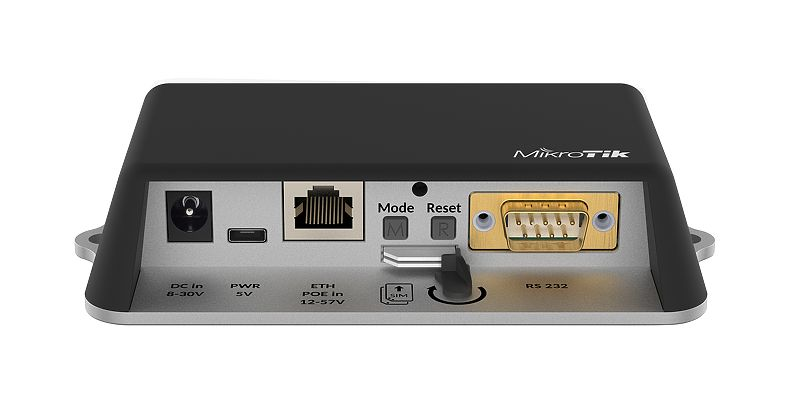
- Direct-input power jack (5.5 mm outside and 2 mm inside, female, pin positive plug) accepts 8-30 V DC.
- microUSB port accepts 5 V powering.
- Ethernet port accepts passive and 802.3af/at Power over Ethernet 8-57 V DC (compensate for the loss on cable, so more than 12 V recommended).
...
- Connect the Ethernet cable from the device to the PoE+DATA port of the PoE adapter.
- Connect an Ethernet cable from your local network (LAN) to the PoE adapter.
- Connect the power cord to the adapter, and then plug the power cord into a power outlet.
 Extension slots and ports
- Built-in 2 GHz wireless access point module, AP/station/bridge/p2p modes are supported. Onboard PIF antennas built-in. Antenna gain1.5 dBi.
- miniPCIe slot and two SIM slots (can't be used without a modem installed, can't be used both at the same time) to be used with a 3G/4G/LTE modem. Onboard antennas available, but openings for external antennas are provided on the case.
- Built-in GPS module - uFL connector provided for an external antenna. To enable, set the port to serial0 (this disables the DB9 port on the unit).
- One 10/100 Ethernet port, supporting automatic cross/straight cable correction (Auto MDI/X). Either straight or crossover cable can be used for connecting to other network devices. The Ethernet port accepts 12-57 V DC powering from a passive PoE injector.
- One DB9 RS232 serial port for serial console access. Configured as 115200 bit/s, 8 data bits, 1 stop bit, no parity. Can't be used if built-in GPS is enabled on serial0.
- One microUSB 2.0 port for powering only.
...
RouterOS includes many configuration options in addition to what is described in this document. We suggest to start starting here to get yourself accustomed to the possibilities: https://mt.lv/help. In case IP connection is not available, the Winbox tool (https://mt.lv/winbox) can be used to connect to the MAC address of the device from the LAN side (all access is blocked from the internet port by default).
For recovery purposes, it is possible to boot the device from the network, see section Buttons and jumpers LtAP mini-series.
miniPCIe slot usage
The device is equipped with a miniPCIe slot and factory-installed LTE modem. Two SIM slots are provided for use together with a miniPCIe modem. The SIM slot is not usable used separately.
In this case, an internal antenna is connected to the modem. Replacing a miniPCIe module should be done by a qualified person, please follow safety precautions when handling electrical equipment:
- Use a wrist grounding strap when unpacking and working with electrical components to avoid electrical discharge (ESD) damage.
- Open the front cover by unscrewing one screw with the Philips PH2 screwdriver.
- Remove four screws on the bottom of the case and lift off the top part of the case. You will see the antenna attached to it.
- Locate the miniPCIe card on the PCB and remove two screws.
- Attach provided a thick thermal pad to the card, and install the card into miniPCIe slot so that the thermal pad is between PCB and card.
...
- The secure card in place using previously removed two screws.
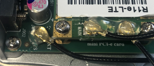
- Attach the grey uFL connector to the MAIN antenna connector of the modem, attach the black cable to the secondary (or AUX) connector.
- To use external antennas, attach antenna connectors and use a 6.5 mm drill bit to drill holes on the side of the unit. (see "
...
- LtAP mini-series") description 4.
- Please see the picture bellow on how to place rubber seals for the best water protection.
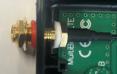
- Attach antenna connectors to the installed card and GPS connector on the PCB, as additional rubber silicone can be used to secure connectors in place on card and PCB board.
Attach a thinner thermal pad to the top of the card.
- Reassembly in back order.
After you have reinserted the device into the case and secured it with the screws that were removed earlier, slide in the SIM cards from your mobile operator into the SIM slots, with the chips facing as shown on the port label. The slot accepts miniSIM (2FF). Close the black latch for SIM cards, to secure them in the slots.
GPS usage
In order to use GPS, an external antenna is needed to connect.
We recommend to use the "ACGPSA" - can be obtained separately. ACGPSA is standalone active GPS antenna, that works in 1575.4 MHz spectrum. Antenna size is 46.5 mm x 26.5 mm x 12.5 mm with an IP67 rating and includes an internal magnet and double-sided tape, so it can easily be attached to various surfaces. It has a long 5m cable with an SMA connector, to be connected to LtAP mini via the ACSMAUFL pigtail (not included, product code ACSMAUFL)
https://mikrotik.com/product/acgpsa
https://mikrotik.com/product/acsmaufl
To connect a GPS antenna, see "miniPCIe slot usage" step 10.
The GPS uses an active antenna, connect only when power is turned off.
...
...
Buttons and jumpers
Reset button
- Hold this button during boot time until LED light starts flashing, release the button to reset RouterOS configuration (total 5 seconds).
- Keep holding for 5 more seconds, LED turns solid, release now to turn on CAP mode. The device will now look for a CAPsMAN server (total 10 seconds).
- Or keep holding the button for 5 more seconds until LED turns off, then release it to make the RouterBOARD look for Netinstall servers (total 15 seconds).
Regardless of the above option used, the system will load the backup RouterBOOT loader if the button is pressed before power is applied to the device. Useful for RouterBOOT debugging and recovery.
Mode button
The action of the mode buttons can be configured from RouterOS software to execute any user-supplied RouterOS script. You can also disable this button. The mode button can be configured in RouterOS menu /system routerboard mode-button
...
- DC ⎓ Switching Power Supply 24 V, 1.2 A, 28.8 W, 86.8 %, VI, cable:220 cm RA DC.
- Cable DC ⎓ plug RA 5.5x2.1x10.5 to Striped 2*24 AWG Tin 8 mm, length 0.35 m.
- PoE Injector with shielded Ethernet cable/connector (RBPoE).
- DC ⎓ 24 V 1.2 A power adapter.
- Mounting kit K-55 vmsVMS.
- Elastic thermal pad, 25x40x3.5 mm.
...
For more information about this product, specification, and pictures please visit our web page: {+}https://mikrotik.com/product/ltap_mini_lte_kit+![]()
![]()
Operating system support
The device supports RouterOS software version 6. The specific factory-installed version number is indicated in the RouterOS menu /system resource. Other operating systems have not been tested.
MikroTik mobile app
Use the MikroTik smartphone app to configure your router in the field, or to apply the most basic initial settings for your MikroTik home access point.

- Scan QR code and choose your preferred OS.
- Install and open application.
- By default, the IP address and user name will be already entered.
- Click Connect to establish a connection to your device through a wireless network.
- Choose Quick setup and application will guide you through all basic configuration settings in a couple of easy steps.
- Advanced An advanced menu is available to fully configure all necessary settings.
...
FCC Caution: Any changes or modifications not expressly approved by the party responsible for compliance could void the user's authority to operate this equipment.
This device complies with Part 15 of the FCC Rules. Operation is subject to the following two conditions: (1) This device may not cause harmful interference, and (2) this device must accept any interference received, including interference that may cause undesired operation. This device and its antenna must not be co-located or operation in conjunction with any other antenna or transmitter.
Contains FCC ID: TV7R11ELTE, TV7R11E4G
IMPORTANT: Exposure to Radio Frequency Radiation.
This equipment complies with the FCC RF radiation exposure limits set forth for an uncontrolled environment. This equipment should be installed and operated with a minimum distance of 20 cm between the radiator and any part of your body.
For use of CBRS bands, the CBSD Category of the final Host equipment will be dependent on the power settings and antenna gain used.
...
IC:7442A-912R2NDLTM
This device complies with Industry Canada licence-exempt RSS standard(s). Operation is subject to the following two conditions: (1) this device may not cause interference, and (2) this device must accept any interference, including interference that may cause undesired operation of the device.
Le présent appareil est conforme aux CNR d'Industrie Canada applicables aux appareils radio exempts de licence. L'exploitation est autorisée aux deux conditions suivantes : (1) l'appareil ne doit pas produire de brouillage, et (2) l'utilisateur de l'appareil doit accepter tout brouillage radioélectrique subi, même si le brouillage est susceptible d'en compromettre le fonctionnement.
Contains IC: 7442A-R11ELTE, 7442A-R11E4G
IMPORTANT: Exposure to Radio Frequency Radiation.
This equipment complies with the IC radiation exposure limits set forth for an uncontrolled environment. This equipment should be installed and operated with a minimum distance of 20 cm between the radiator and any part of your body.
Cet équipement est conforme aux limites d'exposition au rayonnement IC définies pour un environnement non contrôlé. Cet équipement doit être installé et utilisé à une distance minimale de 20 cm entre le radiateur et toute partie de votre corps.
CAN ICES-3 (B)/NMB-3(B)
...
Manufacturer: Mikrotikls SIA, Brivibas gatve 214i Riga, Latvia, LV1039.
BG | С настоящото Mikrotīkls SIA декларира, че този тип радиосъоръжение RouterBOARD е в съответствие с Директива 2014/53/ЕС. Цялостният текст на ЕС декларацията за съответствие може да се намери на следния интернет адрес: https://mikrotik.com/products |
CS | Tímto Mikrotīkls SIA prohlašuje, že typ rádiového zařízení RouterBOARD je v souladu se směrnicí 2014/53/EU. Úplné znění EU prohlášení o shodě je k dispozici na této internetové adrese: https://mikrotik.com/products |
DA | Hermed erklærer Mikrotīkls SIA , at radioudstyrstypen RouterBOARD er i overensstemmelse med direktiv 2014/53/EU. EU-overensstemmelseserklæringens fulde tekst kan findes på følgende internetadresse: https://mikrotik.com/products |
DE | Hiermit erklärt Mikrotīkls SIA , dass der Funkanlagentyp RouterBOARD der Richtlinie 2014/53/EU entspricht. Der vollständige Text der EU-Konformitätserklärung ist unter der folgenden Internetadresse verfügbar: https://mikrotik.com/products |
EL | Με την παρούσα ο/η Mikrotīkls SIA , δηλώνει ότι ο ραδιοεξοπλισμός RouterBOARD πληροί την οδηγία 2014/53/ΕΕ. Το πλήρες κείμενο της δήλωσης συμμόρφωσης ΕΕ διατίθεται στην ακόλουθη ιστοσελίδα στο διαδίκτυο: https://mikrotik.com/products |
EN | Hereby, Mikrotīkls SIA declares that the radio equipment type RouterBOARD is in compliance with Directive 2014/53/EU. The full text of the EU declaration of conformity is available at the following internet address: https://mikrotik.com/products |
ES | Por la presente, Mikrotīkls SIA declara que el tipo de equipo radioeléctrico RouterBOARD es conforme con la Directiva 2014/53/UE. El texto completo de la declaración UE de conformidad está disponible en la dirección Internet siguiente: https://mikrotik.com/products |
ET | Käesolevaga deklareerib Mikrotīkls SIA , et käesolev raadioseadme tüüp RouterBOARD vastab direktiivi 2014/53/EL nõuetele. ELi vastavusdeklaratsiooni täielik tekst on kättesaadav järgmisel internetiaadressil: https://mikrotik.com/products |
FI | Mikrotīkls SIA vakuuttaa, että radiolaitetyyppi RouterBOARD on direktiivin 2014/53/EU mukainen. EU-vaatimustenmukaisuusvakuutuksen täysimittainen teksti on saatavilla seuraavassa internetosoitteessa: https://mikrotik.com/products |
FR | Le soussigné, Mikrotīkls SIA , déclare que l'équipement radioélectrique du type RouterBOARD est conforme à la directive 2014/53/UE. Le texte complet de la déclaration UE de conformité est disponible à l'adresse internet suivante: https://mikrotik.com/products |
HR | Mikrotīkls SIA ovime izjavljuje da je radijska oprema tipa RouterBOARD u skladu s Direktivom 2014/53/EU. Cjeloviti tekst EU izjave o sukladnosti dostupan je na sljedećoj internetskoj adresi: https://mikrotik.com/products |
HU | Mikrotīkls SIA igazolja, hogy a RouterBOARD típusú rádióberendezés megfelel a 2014/53/EU irányelvnek. Az EU-megfelelőségi nyilatkozat teljes szövege elérhető a következő internetes címen: https://mikrotik.com/products |
IT | Il fabbricante, Mikrotīkls SIA , dichiara che il tipo di apparecchiatura radio RouterBOARD è conforme alla direttiva 2014/53/UE. Il testo completo della dichiarazione di conformità UE è disponibile al seguente indirizzo Internet: https://mikrotik.com/products |
IS | Hér með lýsir Mikrotīkls SIA því yfir að RouterBOARD er í samræmi við grunnkröfur og aðrar kröfur, sem gerðar eru í tilskipun 2014/53/EU. |
LT | Aš, Mikrotīkls SIA , patvirtinu, kad radijo įrenginių tipas RouterBOARD atitinka Direktyvą 2014/53/ES. Visas ES atitikties deklaracijos tekstas prieinamas šiuo interneto adresu: https://mikrotik.com/products |
LV | Ar šo Mikrotīkls SIA deklarē, ka radioiekārta RouterBOARD atbilst Direktīvai 2014/53/ES. Pilns ES atbilstības deklarācijas teksts ir pieejams šādā interneta vietnē: https://mikrotik.com/products |
MT | B'dan, Mikrotīkls SIA , niddikjara li dan it-tip ta' tagħmir tar-radju RouterBOARD huwa konformi mad-Direttiva 2014/53/UE. It-test kollu tad-dikjarazzjoni ta' konformità tal-UE huwa disponibbli f'dan l-indirizz tal-Internet li ġej: https://mikrotik.com/products |
NL | Hierbij verklaar ik, Mikrotīkls SIA , dat het type radioapparatuur RouterBOARD conform is met Richtlijn 2014/53/EU. De volledige tekst van de EU-conformiteitsverklaring kan worden geraadpleegd op het volgende internetadres: https://mikrotik.com/products |
NO | Mikrotīkls SIA erklærer herved at utstyret RouterBOARD er i samsvar med de grunnleggende krav og øvrige relevante krav i direktiv 2014/53/EU. Den fulle teksten til EU-samsvarserklæringen er tilgjengelig på følgende internettadresse: https://mikrotik.com/products |
PL | Mikrotīkls SIA niniejszym oświadcza, że typ urządzenia radiowego RouterBOARD jest zgodny z dyrektywą 2014/53/UE. Pełny tekst deklaracji zgodności UE jest dostępny pod następującym adresem internetowym: https://mikrotik.com/products |
PT | O(a) abaixo assinado(a) Mikrotīkls SIA declara que o presente tipo de equipamento de rádio RouterBOARD está em conformidade com a Diretiva 2014/53/UE. O texto integral da declaração de conformidade está disponível no seguinte endereço de Internet: https://mikrotik.com/products |
RO | Prin prezenta, Mikrotīkls SIA declară că tipul de echipamente radio RouterBOARD este în conformitate cu Directiva 2014/53/UE. Textul integral al declarației UE de conformitate este disponibil la următoarea adresă internet: https://mikrotik.com/products |
SK | Mikrotīkls SIA týmto vyhlasuje, že rádiové zariadenie typu RouterBOARD je v súlade so smernicou 2014/53/EÚ. Úplné EÚ vyhlásenie o zhode je k dispozícii na tejto internetovej adrese: https://mikrotik.com/products |
SL | Mikrotīkls SIA potrjuje, da je tip radijske opreme RouterBOARD skladen z Direktivo 2014/53/EU. Celotno besedilo izjave EU o skladnosti je na voljo na naslednjem spletnem naslovu: https://mikrotik.com/products |
SV | Härmed försäkrar Mikrotīkls SIA att denna typ av radioutrustning RouterBOARD överensstämmer med direktiv 2014/53/EU. Den fullständiga texten till EU-försäkran om överensstämmelse finns på följande webbadress: https://mikrotik.com/products |
MPE statement
This equipment complies with EU radiation exposure limits set forth for an uncontrolled environment. This equipment should be installed and operated with minimum distance of 20 cm between the radiator and your body, unless specifically stated otherwise in page 1 of this document. In RouterOS you must specify your country, to make sure local wireless regulations are observed.
This device meets Maximum 2G/3G/4G LTE per ETSI regulations.
 Frequency bands terms of use
Frequency range (for applicable models) | Channels used | Maximum Output Power (EIRP) | Restriction |
2412-2472 MHz | 1 - 13 | 20 dBm | Without any restriction to use in all EU Member States |
5150-5250 MHz | 26 - 48 | 23 dBm | Restricted to indoor use only* |
5250-5350 MHz | 52 - 64 | 20 dBm | Restricted to indoor use only* |
5470-5725 MHz | 100 - 140 | 27 dBm | Without any restriction to use in all EU Member States |
* It is the customer's responsibility to follow local country regulations, including operation within legal frequency channels, output power, cabling requirements, and Dynamic Frequency Selection (DFS) requirements. All Mikrotik radio devices must be professionally installed!
According to Commission Decision 2000/299/EC (6 April 2000), the product falls under the scope of Class 2.Note. Information contained here is subject to change. Please visit the product page on www.mikrotik.com for the most up to date version of this document.![]()
BG. Инструкция: Свържете адаптера на захранване, за да включите устройството. Отворете 192.168.88.1 в уеб браузър, за да настроите продукта. Повече информация в {_}{+}https://mt.lv/help-bg+_![]()
![]()
CS. Návod k použití: Připojte napájecí adaptér k zapnutí přístroje. Otevřete 192.168.88.1 ve webovém prohlížeči pro konfiguraci produktu. Více informací najdete v {_}{+}https://mt.lv/help-cs+_![]()
![]()
DA. Instruktionsbog: Tilslut strømadapteren for at tænde for enheden. Åbn 192.168.88.1 i en webbrowser til at konfigurere produktet. Mere information i {_}{+}https://mt.lv/help-da+_![]()
![]()
DE. Bedienungsanleitung: Verbinden Sie das Netzteil, um das Gerät einzuschalten. Öffnen Sie 192.168.88.1 in einem Web-Browser, um das Produkt zu konfigurieren. Weitere Informationen im {_}{+}https://mt.lv/help-de+_![]()
![]()
EL. εγχειρίδιο οδηγιών: Συνδέστε τον προσαρμογέα τροφοδοσίας για να ενεργοποιήσετε τη μονάδα. Ανοίξτε 192.168.88.1 σε ένα πρόγραμμα περιήγησης στο Web για να διαμορφώσετε το προϊόν. Περισσότερες πληροφορίες στο {_}{+}https://mt.lv/help-el+_![]()
![]()
EN. Instruction manual: Connect the power adapter to turn on the device. Open 192.168.88.1 in your web browser, to configure it. More information on {_}{+}https://mt.lv/help+_![]()
![]()
ES. Manual de instrucciones: Conecte el adaptador de alimentación para encender la unidad. Abra 192.168.88.1 en un navegador web para configurar el producto. Más información en {_}{+}https://mt.lv/help-es+_![]()
![]()
ET. Kasutusjuhend: Ühendage toiteadapter seadme sisselülitamiseks. Avatud 192.168.88.1 in veebilehitseja seadistada toodet. Rohkem teavet {_}{+}https://mt.lv/help-et+_![]()
![]()
FI. Käyttöohje: Kytke virtalähde päälle laitteen. Avaa 192.168.88.1 in selaimen määrittää tuotteen. Lisää tietoa {_}{+}https://mt.lv/help-fi+_![]()
![]()
FR. Mode d'emploi: Connectez l'adaptateur d'alimentation pour allumer l'appareil. Ouvrez 192.168.88.1 dans un navigateur Web pour configurer le produit. Plus d'informations dans {_}{+}https://mt.lv/help-fr+_![]()
![]()
HR. Uputa za uporabu: Priključite napajanje i uključite uređaj. Za konfiguraciju uređaja u pregledniku otvorite 192.168.88.1. Više informacija je na {_}{+}https://mt.lv/help-hr+_![]()
![]()
HU. Használati utasítás: Csatlakoztassa a hálózati adaptert a készülék bekapcsolásához. Megnyitása 192.168.88.1 egy webböngészőben beállítani a terméket. Több információ {_}{+}https://mt.lv/help-hu+_![]()
![]()
IT. Manuale di istruzioni: Collegare l'adattatore di alimentazione per accendere l'unità. Aprire 192.168.88.1 in un browser Web per configurare il prodotto. Maggiori informazioni in {_}{+}https://mt.lv/help-it+_![]()
![]()
IS. Notkunarleiðbeiningar: Tengdu straumbreytinn til að kveikja á tækinu. Opnaðu 192.168.88.1 í vafra til að stilla það. Nánari
upplýsingar á {_}{+}https://mt.lv/help-is+_![]()
![]()
NO. Instruksjonsmanual: Koble strømadapteren for å slå på enheten. Åpne 192.168.88.1 i nettleseren din for å konfigurere den. Mer informasjon på {_}{+}https://mt.lv/help-no+_![]()
![]()
LT. Naudojimosi instrukcija: Prijunkite maitinimo adapterį įjunkite įrenginį. Į interneto naršyklę 192.168.88.1 Atidarykite galite konfigūruoti gaminį. Daugiau informacijos rasite {_}{+}https://mt.lv/help-lt+_![]()
![]()
LV. Lietošanas instrukcija: Pievienojiet Strāvas adapteri, lai ieslēgtu ierīci. Atvērt 192.168.88.1 ar interneta pārlūku, lai konfigurētu produktu. Plašāka informācija {_}{+}https://mt.lv/help-lv+_![]()
![]()
MT. Manwal tal-istruzzjoni: Qabbad l-adapter tal-qawwa biex iddawwar it-tagħmir. Iftaħ 192.168.88.1 fil-web browser tiegħek, biex jiġi kkonfigurat. Aktar informazzjoni fuq {_}{+}https://mt.lv/help-mt+_![]()
![]()
NL. Handleiding: Sluit voedingsadapter aan op het apparaat in te schakelen. Open 192.168.88.1 in een webbrowser om het product te configureren. Meer informatie in {_}{+}https://mt.lv/help-nl+_![]()
![]()
PL. Instrukcja obsługi: Podłącz adapter zasilania, aby włączyć urządzenie. Otwórz 192.168.88.1 w przeglądarce internetowej, aby skonfigurować urządzenie. Więcej informacji w {_}{+}https://mt.lv/help-pl+_![]()
![]()
PT. Manual de instruções: Conecte o adaptador de alimentação para ligar o aparelho. Abra 192.168.88.1 em um navegador da web para configurar o produto. Mais informações em {_}{+}https://mt.lv/help-pt+_![]()
![]()
RO. Instrucțiuni de utilizare: Conectați adaptorul de alimentare pentru a porni aparatul. Deschide 192.168.88.1 într-un browser web pentru a configura produsul. Mai multe informații în {_}{+}https://mt.lv/help-ro+_![]()
![]()
SK. Navodila: Priključite napajalnik za vklop naprave. Odprite 192.168.88.1 v spletnem brskalniku nastaviti izdelek. Več informacij v
{_}{+}https://mt.lv/help-sk+_![]()
![]()
SL. Návod na použitie: Pripojte napájací adaptér k zapnutiu prístroja. Otvorte 192.168.88.1 vo webovom prehliadači pre konfiguráciu produktu. Viac informácií nájdete v {_}{+}https://mt.lv/help-sl+_![]()
![]()
SV. Instruktionsmanual: Anslut nätadaptern för att slå på enheten. Öppna 192.168.88.1 i en webbläsare för att konfigurera produkten. Mer information på {_}{+}https://mt.lv/help-sv+_![]()
![]()
NO. Bruksanvisningen: Koble strømadapteren for å slå på enheten. Åpne 192.168.88.1 i en nettleser for å konfigurere produktet. Mer informasjon på {_}{+}https://mt.lv/help-no+_![]()
![]()
RU. Руководство по эксплуатации: подключите адаптер питания чтобы включить устройство. Откройте 192.168.88.1 в своем веб-браузере для конфигурации. Дополнительная информация https://mt.lv/help-ru
CN. 说明书。 连接电源适配器以打开设备。 在Web浏览器中打开192.168.88.1进行配置。 有关{_}{+}https://mt.lv/help-zh+_![]()
![]() 的更多信息
的更多信息