...
This is the basic VRRP configuration example.
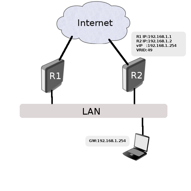

According to this configuration, as long as the master, R1, is functional, all traffic destined to the external network gets directed to R1. But as soon as R1 fails, R2 takes over as the master and starts handling packets forwarded to the interface associated with IP(R1). In this setup Router router "R2" is completely idle during the Backup period.
Configuration
...
| Code Block | ||
|---|---|---|
| ||
/ip address add address=192.168.1.1/24 interface=ether1 /interface vrrp add interface=ether1 vrid=49 priority=254 /ip address add address=192.168.1.2541/32 interface=vrrp1 |
R2 configuration:
| Code Block | ||
|---|---|---|
| ||
/ip address add address=192.168.1.2/24 interface=ether1 /interface vrrp add interface=ether1 vrid=49 /ip address add address=192.168.1.2541/32 interface=vrrp1 |
Testing
First of all, check if both routers have correct flags at VRRP interfaces. On router R1 it should look like this
...
As you can see VRRP interface MAC addresses are identical on both routers. Now to check if VRRP is working correctly, try to ping the virtual address from a client and check ARP entries:
| Code Block | ||
|---|---|---|
| ||
[admin@client] > /ping 192.168.1.2541 192.168.1.254 64 byte ping: ttl=64 time=10 ms 192.168.1.254 64 byte ping: ttl=64 time=8 ms 2 packets transmitted, 2 packets received, 0% packet loss round-trip min/avg/max = 8/9.0/10 ms [admin@client] /ip arp> print Flags: X - disabled, I - invalid, H - DHCP, D - dynamic # ADDRESS MAC-ADDRESS INTERFACE ... 1 D 192.168.1.2541 00:00:5E:00:01:31 bridge1 |
Now unplug the ether1 cable on router R1. R2 will become VRRP master, and the ARP table on a client will not change but traffic will start to flow over the R2 router.
| Info |
|---|
In case VRRP is used with Reverse Path Filtering, then it is recommended that |
...