...
- Remove the upper cover (see "Removing upper cover").
- Connect an external antenna to the SMA connector (see "Antenna usage").
- Open the bottom cover (see "Opening bottom cover").
- Connect the device to the power source (see "Powering").
- Open network connections on your PC, mobile phone or other device and search for MikroTik wireless network and connect to it.
- Recommended using the WinBox configuration tool https://mt.lv/winbox.
- Default IP for the device is 192.168.88.1, user name: admin and there is no password.
- Depending on the antenna used, you must set its gain in the RouterOS software to ensure that EIRP meets the limit set by the local authorities. This is done in the Wireless menu.
- We recommend clicking the "Check for updates" button and updating your RouterOS software to the latest version to ensure the best performance and stability.
- Choose your country, to apply country regulation settings and set up your password in the screen that loads.
...
- Connect the Ethernet cable from the device to the PoE+DATA port of the PoE adapter.
- Connect an Ethernet cable from your local network (LAN) to the PoE adapter.
- Connect the power cord to the adapter, and then plug the power cord into a power outlet.
MikroTik mobile app
Use the MikroTik smartphone app to configure your router in the field, or to apply the most basic initial settings for your MikroTik home access point.

- Scan QR code and choose your preferred OS.
- Install and open application.
- By default, IP address and user name will be already entered.
- Click Connect to establish a connection to your device through a wireless network.
- Choose Quick setup and application will guide you through all basic configuration settings in a couple of easy steps.
- Advanced menu is available to fully configure all necessary settings.
Removing upper cover
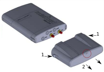
- To remove the upper cover, press both side clips.
- Pull cover to the side while holding the body. When assembling please not mark on the top cover or reference.
...
- Guide hose clamp through the opening on the back of the device and attach it to the mast.
- Align and secure with hose clamp screw using PH2 screwdriver.
- The device should be always placed by TOP cover facing upwards.
- Connect your antenna.
- Antenna The antenna is no provided with the device only for illustration purposes.
...
The installation infrastructure (towers and masts), must be properly grounded.
Please secure all loose Ethernet cables and antenna cables to the pole or mast approximately at 30cm from the device, so that the cable weight is not pulling the ports and connectors.
...
When mounting on DIN rail, please find a special bracket in the package and secure it with four screws to the back of the unit. With the attached mounting bracket you will be able to slide the device on the DIN rail.
...
RouterOS allows configuring each LEDs LED's activity the way that the user wishes. It is possible to configure the LEDs to display wireless strength, blink the LEDs on interface traffic activity and many other options. For further information please visit https://wiki.mikrotik.com/wiki/Manual:System/LEDS
Default factory configuration for this device:
...
For more information about this product, specifications, pictures, downloads and test results please visit our web page: https://mikrotik.com/product/RB911G-5HPacD-NB
https://i.mt.lv/cdn/rb_files/NetBox-1566373542.pdf
- RB911G-5HPacD-NB-US (USA) is factory locked for 5170-5250MHz and 5725-5835MHz frequencies. This lock can not be removed.
- RB911G-5HPacD-NB (International) supports 5150MHz-5875MHz range (Specific frequency range can be limited by country regulations).
...