...
More advanced firewall setups, or complicated tasks, such as traffic prioritization, routing policies, where it is necessary to utilize more than one RouterOS facility, require knowledge: How do these facilities work together? What happens when and why?
RouterOS packet flow diagram and flow examples will try to answers answer these questions.
It would be very complicated to represent what is going on with the packet in one diagram, therefore a packet flow diagram is divided into three parts:
- overall diagram;
- detailed bridging, routing, and MPLS flow diagram;
- a diagram that shows what facilities and in what order is are included in prerouting, input, forward, output, and postrouting.
...
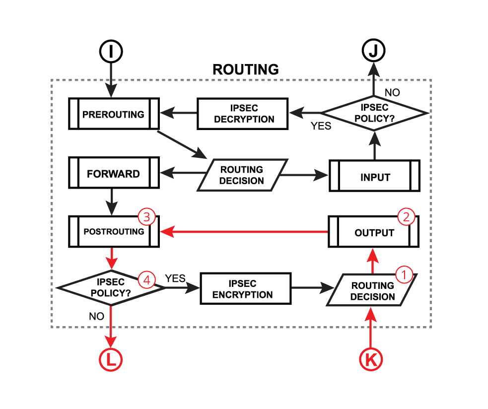
There are 4 boxes in the center of the diagram: Bridging, Routing, Mpls decisions, and local router processes. So for example, if the packet needs to be routed over the router, a packet will flow as illustrated in the image below. Without looking deeper into each facility, the packet enters the in-interface, the router determines that it is IP traffic and needs to be routed, the packet goes through all routing processes and exits the out-interface.
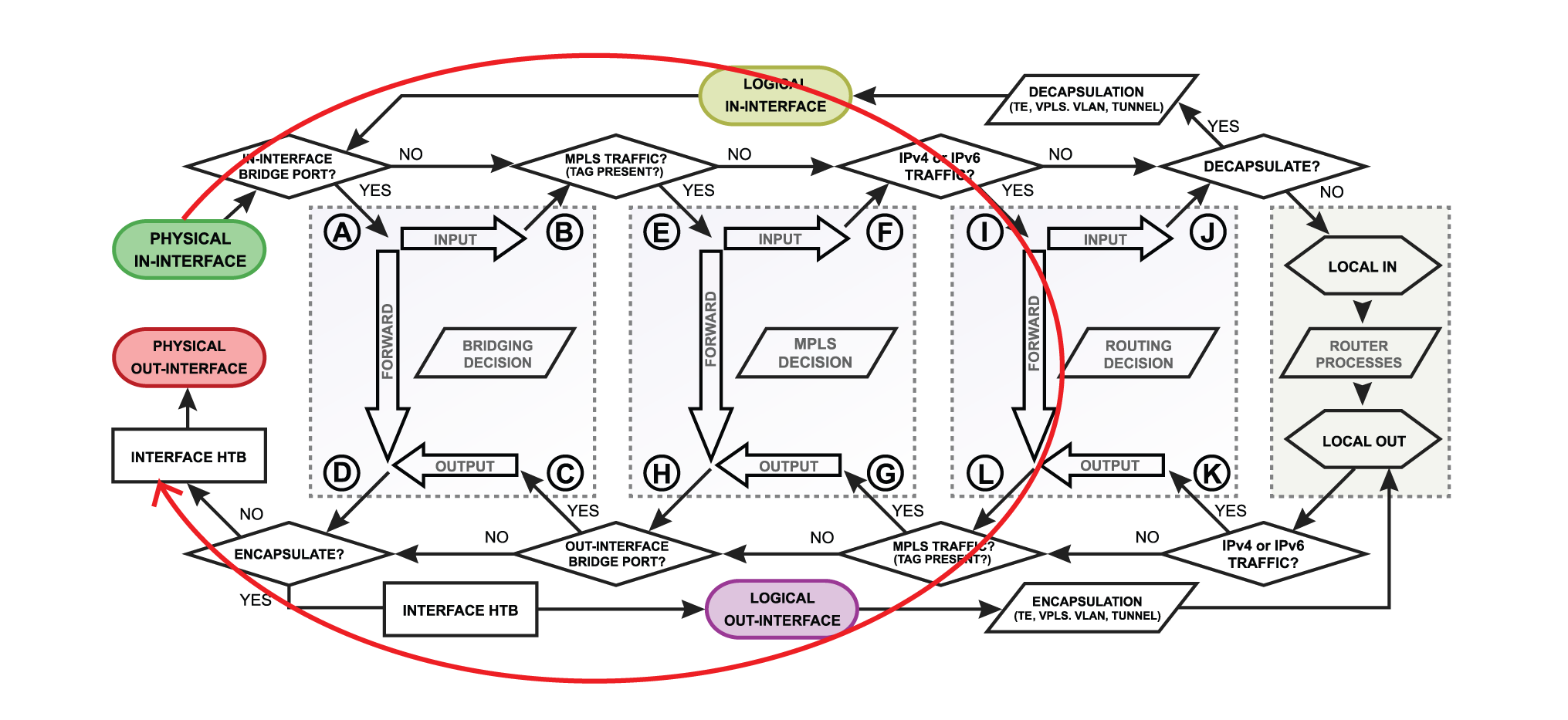 Let's take a look at another example that will illustrate what happens if the packet's destination is a router. For example, the in-interface receives ICMP (ping) packet, its destination is the router itself, so the packet will go for local-in processing. After the packet is processed ICMP (ping) reply is generated inside the router (local-out processing) and will be sent out over the out-interface.
...
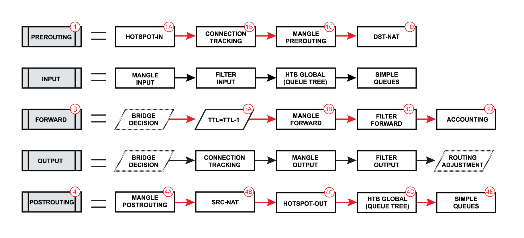
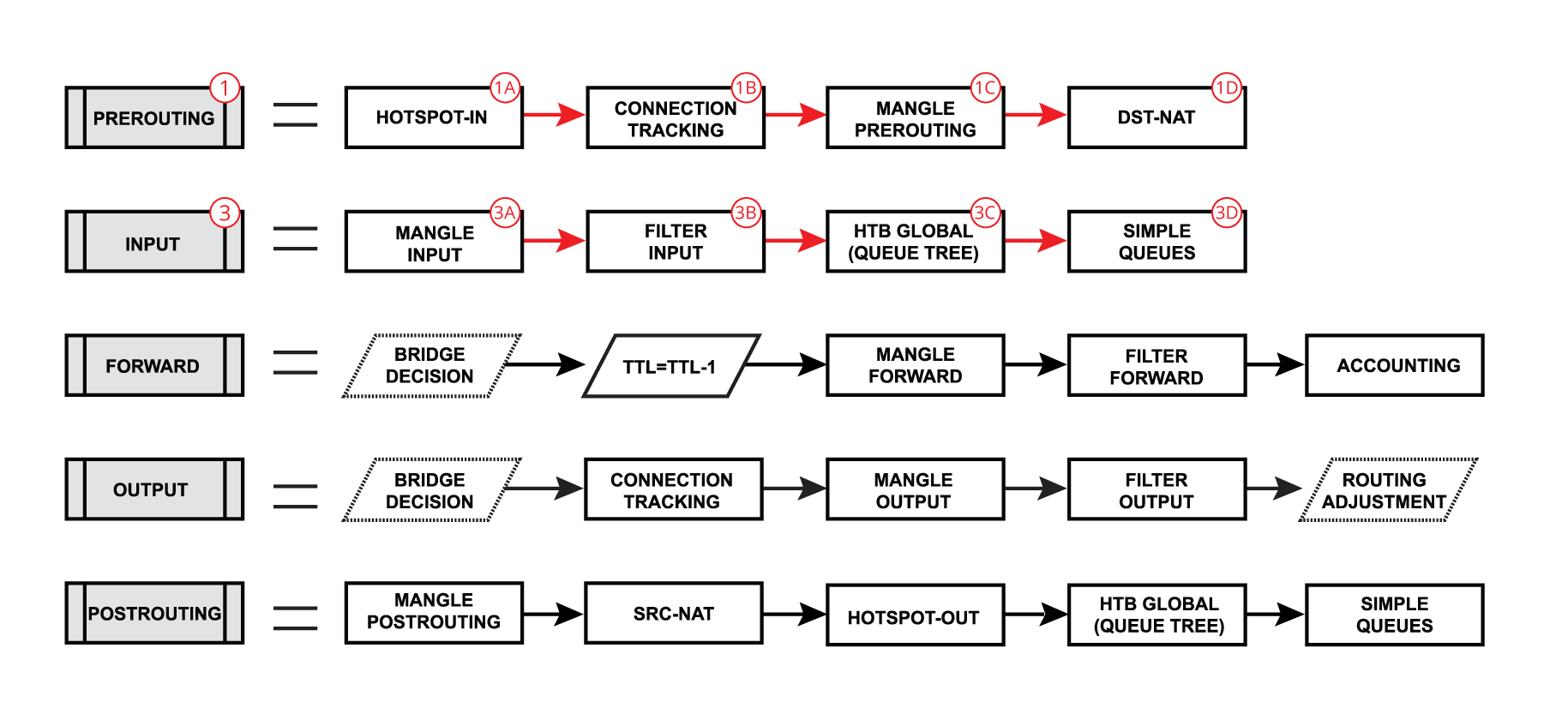
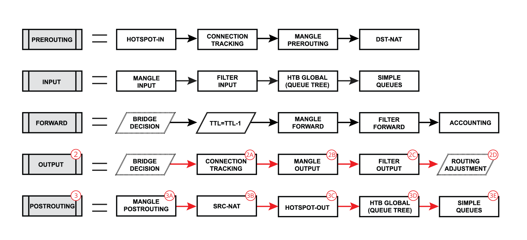
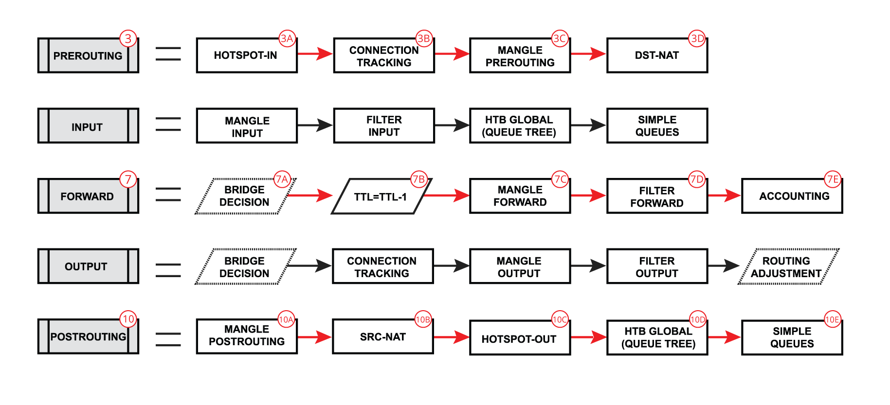
Each of the prerouting, input, forward, output, and postrouting blocks contain contains even more facilities, which are illustrated in the third part of the packet flow diagram:
...
A simple explanation of each box before we go further with examples:
- Hotspot-in - allow allows to capture traffic which that otherwise would be discarded by connection tracking - this way our Hotspot feature is able to provide connectivity even if networks settings are an incomplete mess ;
- RAW Prerouting - RAW table prerouting chain;
- Connection tracking - packet is processed by connection tracking;
- Mangle Prerouting - Mangle prerouting chain;
- Mangle Input - Mangle input chain;
- Filter Input - Firewall filter input chain;
- HTB Global - Queue tree;
- Simple Queues - ;
- TTL - indicates an exact place where the Time To Live (TTL) of the routed packet is reduced by 1 if TTL becomes 0, a packet will be discarded;
- Mangle Forward - Mangle forward chain;
- Filter Forward - Mangle forward chain;
- Accounting - Authentication, Authorization, and Accounting feature processing;
- RAW Output - RAW table output chain;
- Mangle Output - Mangle output chain;
- Filter Output - Firewall filter output chain;
- Routing Adjustment - this is a workaround that allows to set - up policy routing in mangle chain output (routing-mark) ;
- Mangle Postrouting - Mangle postrouting chain;
- Src Nat - Network Address Translation srcnat chain;
- Dst Nat - Network Address Translation dstnat chain;
- Hotspot-out - undo all that was done by hotspot-in for the packets that are going back to the client;
...
Now, let's take our first example where the packet gets routed over the router and look deeper through what facilities packet goes:
| Section | ||||||||||
|---|---|---|---|---|---|---|---|---|---|---|
|
...
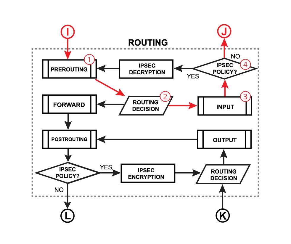
We already learned that packet goes into the in-interface, the router determines that it is an IP packet and need needs to be routed, and here starts the complicated process:
| Section | ||||||||||
|---|---|---|---|---|---|---|---|---|---|---|
|
...
| Section | ||||||||||
|---|---|---|---|---|---|---|---|---|---|---|
|
...
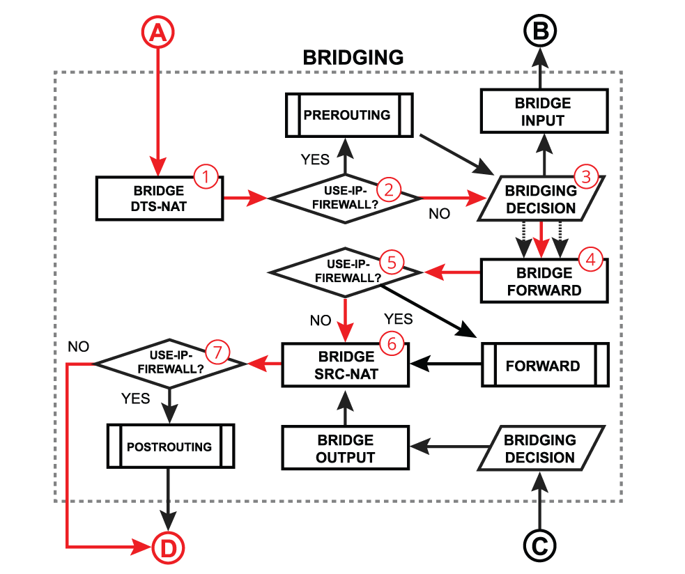
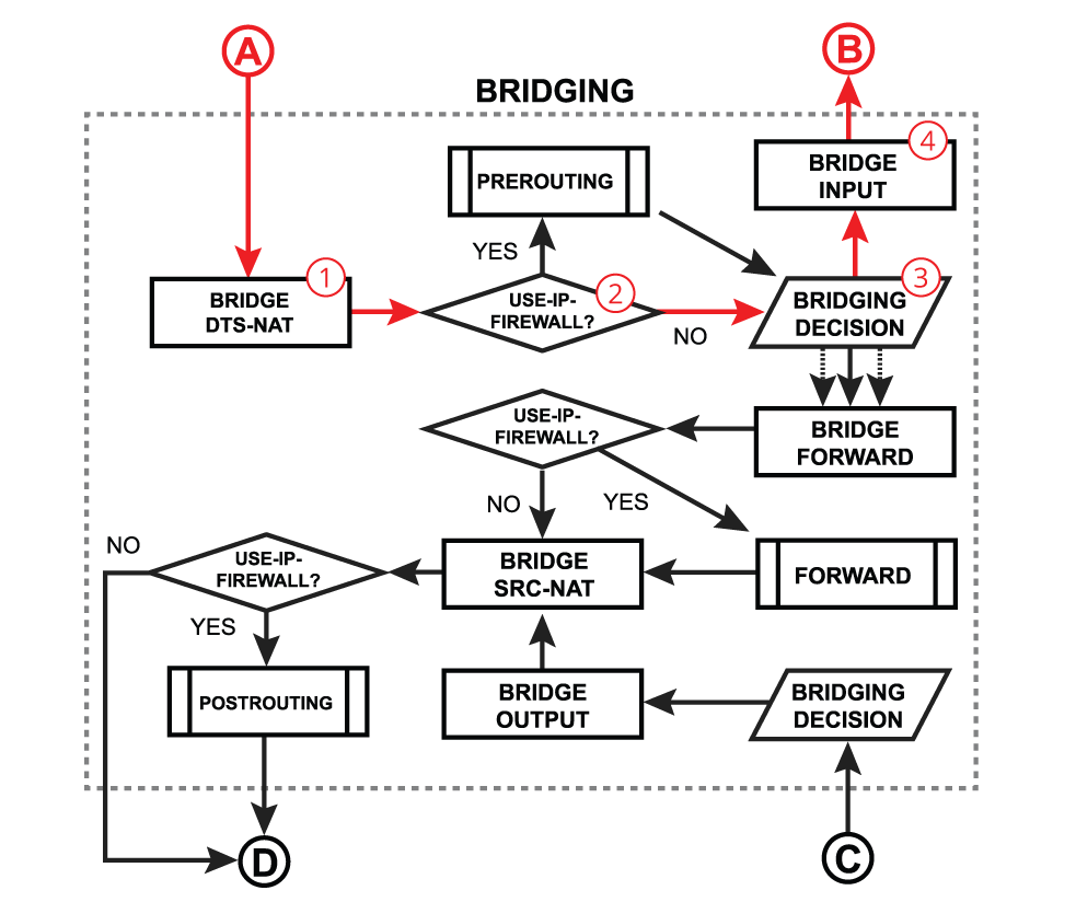
Bridge forward is a process that takes place when a packet is forwarded from one bridge port to another, essentially connecting multiple devices on the same network. After receiving a packet on the in-interface, the device determines that the in-interface is a bridge port, so it gets passed through the bridging process:
| Section | ||||||||||
|---|---|---|---|---|---|---|---|---|---|---|
|
...
| Info |
|---|
When bridge Tagged packets might get decapsulated on the "BRIDGING DECISION" block, which means these packets will no longer match the |
...
Bridge input is a process that takes place when a packet is destined to for the bridge interface. Most commonly this happens when you need to reach some services that are running on the bridge interface (e.g. a DHCP server) or you need to route traffic to other networks. The very first steps are similar to the bridge forward process - after receiving a packet on the in-interface, the device determines that the in-interface is a bridge port, so it gets passed through the bridging process:
| Section | ||||||||||
|---|---|---|---|---|---|---|---|---|---|---|
|
...
Bridge output is a process that takes place when a packet should exit the device through one or multiple bridge ports. Most commonly this happens when a bridge interface itself tries to reach a device connected to a certain bridge port (e.g. when a DHCP server running on a bridge interface is responding to a DHCP client). After a packet is processed on other higher-level RouterOS processes and the device finally determines that the output interface is a bridge, the packet gets passed through the bridging process:
...
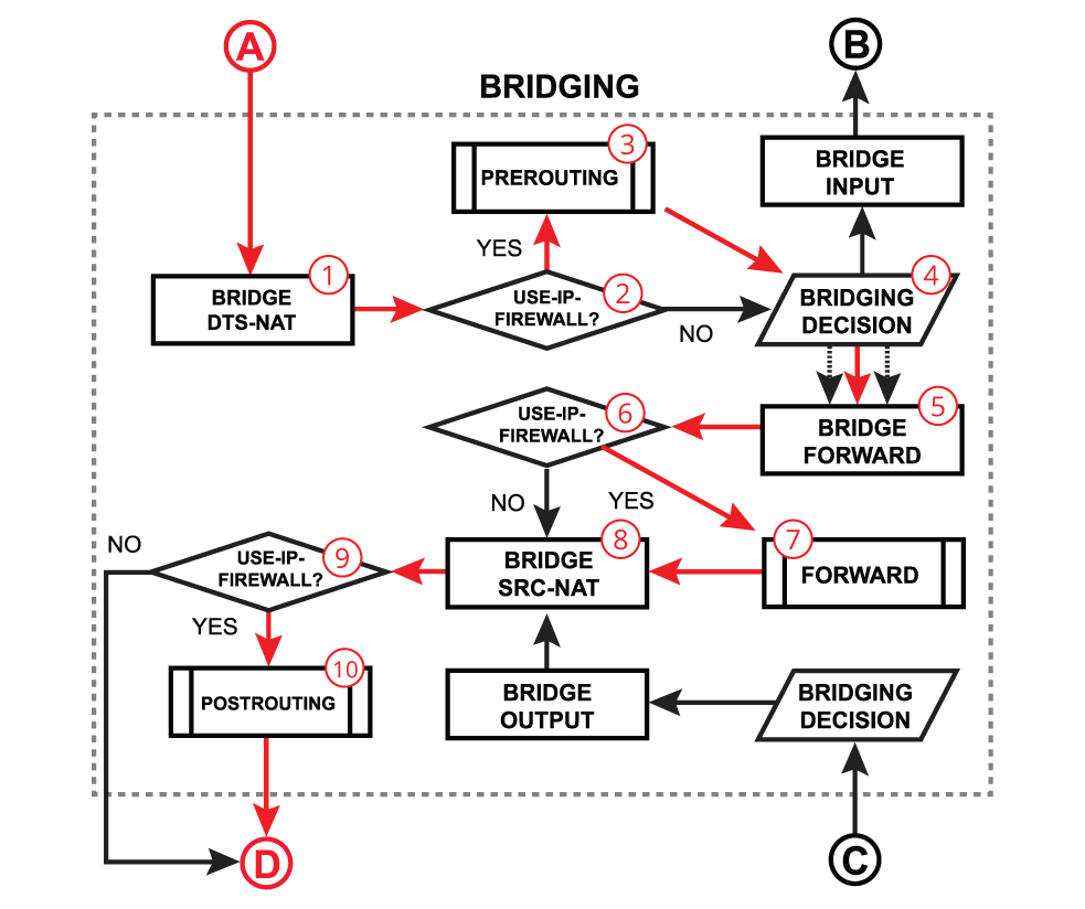
In certain network configurations, you might need to enable additional processing on routing chains for bridged traffic, for example, to use simple queues or an IP firewall. This can be done when the use-ip-firewall is enabled under the bridge settings. Note that additional processing will consume more CPU resources to handle these packets. All the steps were already discussed in previous points, below is a recap:
| Section | ||||||||||
|---|---|---|---|---|---|---|---|---|---|---|
|
...
On the previous topic, we solely discussed a software bridging that requires the main CPU processing to forward packets through the correct bridge port. Most of the MikroTik devices are equipped with dedicated switching hardware, the so-called switch chip or switch ASIC. This allows us to offload some of the bridging functions, like packet forwarding between bridge ports or packet filtering, to this specialized hardware chip without consuming any CPU resources. In RouterOS, we have named this function as Bridge Hardware (HW) Offloading. Different MikroTik devices might have different switch chips and each chip has a different set of features available, so make sure to visit this article to get more details - Bridge Hardware Offloading.
...
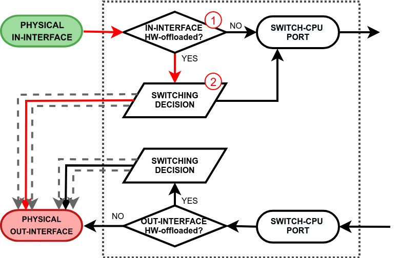
- switching decision - widely depends on the switch model. This block controls all the switching-related tasks, like host learning, packet forwarding, filtering, rate-limiting, VLAN tagging/untagging, mirroring, etc. Certain switch configuration configurations can alter the packet flow;
- switch-cpu port - a special purpose switch port for communication between the main CPU and other switch ports. Note that the switch-cpu port does not show up anywhere on RouterOS except for the switch menu, none of the software-related configuration configurations (e.g. interface-list) can be applied to this port. Packets that reach the CPU are automatically associated with the physical in-interface.
...
| Section | ||||||||||
|---|---|---|---|---|---|---|---|---|---|---|
|
...
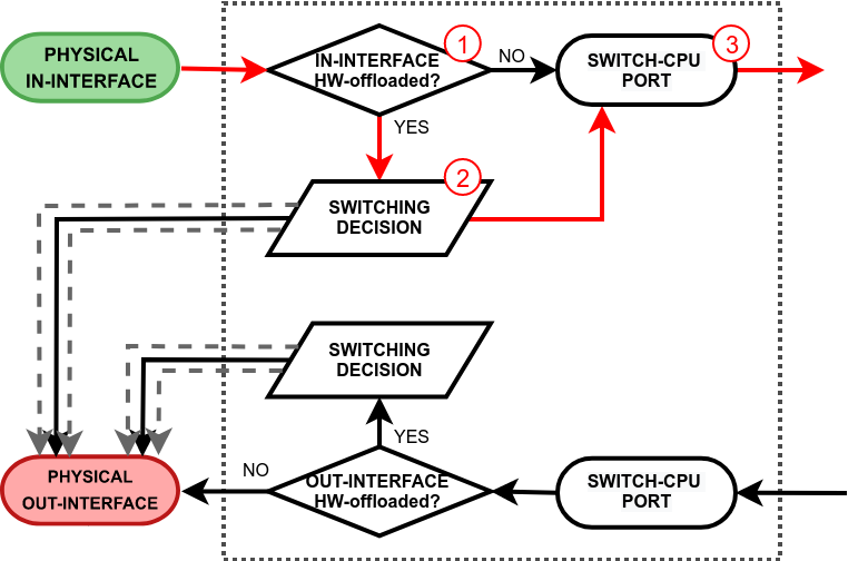
This process takes place when a packet is received on a physical interface and it is destined to switch-cpu port for further software processing. There are two paths to the switch-cpu. One where hardware offloading and switching is not even used (e.g. a standalone interface for routing or a bridged interface but with deliberately disabled HW offloading), so the packet is simply passed further for software processing. Another path is taken when hardware offloading is active on the in-interface. This will cause the packet to pass through the switching decision and there are various reasons why the switch might forward the packet to the switch-cpu port:
...
| Section | ||||||||||
|---|---|---|---|---|---|---|---|---|---|---|
|
...
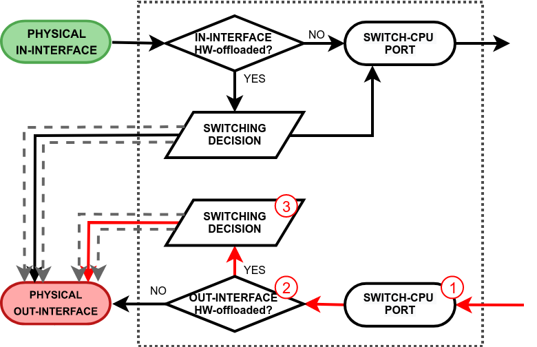
This process takes place when a packet exits the RouterOS software processing and it is received on the switch-cpu port. Again, there are two paths the packet can take. One where hardware offloading and switching is are not even used (e.g. a standalone interface for routing or a bridged interface but with deliberately disabled HW offloading), so the packet is simply sent out through the physical out-interface. Another path is taken when hardware offloading is active on the out-interface. This will cause the packet to pass through the switching decision. Just like any other switch port, the switch will learn the source MAC addresses from packets that are received on the switch-cpu port. This does come in handy when a bridge contains HW and non-HW offloaded interfaces, so the switch can learn which frames should be forwarded to the CPU. See the packet walkthrough when an out-interface is hardware offloaded:
| Section | ||||||||||
|---|---|---|---|---|---|---|---|---|---|---|
|
...
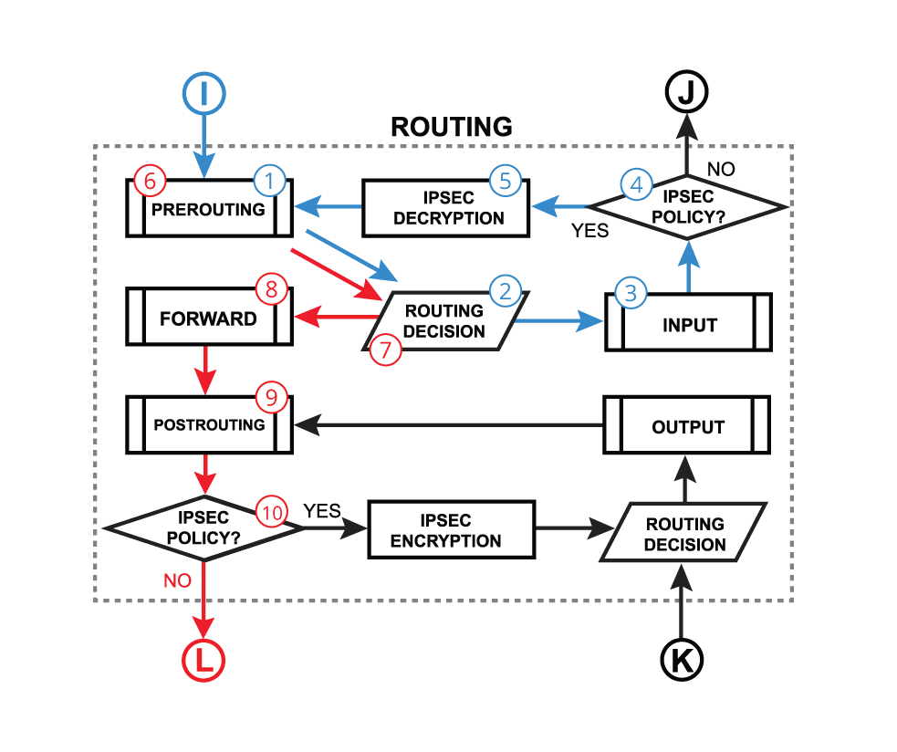
Let's assume that there is an IPIP packet coming in into the router. Since it is a regular ipv4 packet it will be processed through all routing-related facilities ( until "J" in the diagram). Then the router will look if the packet needs to be decapsulated., in this case, it is an IPIP packet so "yes" send the packet to decapsulation. After that packet will go another loop through all the facilities but this time as a decapsulated IPv4 packet.
It is very important because the packet actually travels through the firewall twice, so if there is a strict firewall, then there should be "accept" rules for IPIP encapsulated packet packets as well as a decapsulated IP packetpackets.
| Info |
|---|
Packet encapsulation and decapsulation using a bridge with enabled |
IPSec Policies
...
| Section | |||||||
|---|---|---|---|---|---|---|---|
|
...
| Section | |||||||
|---|---|---|---|---|---|---|---|
|
...
From what we learned so far, it is quite obvious that such packet processing takes a lot of CPU resources. To fast things up FastPath was introduced since in the first RouterOS v6. What it does is it skips processing in the Linux kernel, basically trade trading some RouterOS functionality for performance. For FastPath to work, interface driver support and specific configuration conditions are required.
...
FastPath is an interface driver extension, that allows a driver to talk directly to specific RouterOS facilities and skipping skip all others.

The packet can be forwarded by a fast path handler only if at least the source interface supports a fast path. For complete fast-forwarding, destination interface support is also required.
...
Traffic Generator and MPLS automatically use FastPath if the interface supports this feature. Currently, MPLS fast-path applies only to MPLS switched traffic (frames that enter router as MPLS and must leave router as MPLS) - MPLS ingress and egress (including VPLS tunnel endpoints that do VPLS encap/decap) will operate as before.
A Bridge handler is used if the following conditions are met:
- there are no bridge Calea, filter, NAT rules;
- use-ip-firewall is disabled;
- no mesh, MetaRouter interface configuration;
- sniffer, torch, and traffic generator are not running;
- bridge vlan-filtering is disabled (condition is removed since RouterOS 7.2 version);
- bridge dhcp-snooping is disabled.
| Note |
|---|
FastPath on the vlan-filtering bridge does NOT support priority-tagged packets (packets with VLAN header but VLAN ID = 0). Those packets are redirected via a slow path. |
...
EoIP, Gre, IPIP, and L2TP interfaces have per-interface setting allow-fast-path. Allowing a fast path on these interfaces has a side effect of bypassing firewall, connection tracking, simple queues, queue tree with parent=global, IP accounting, IPsec, hotspot universal client, vrf assignment for encapsulated packets that go trough through a fast-path. Also, packet fragments cannot be received in FastPath.
| Note |
|---|
FastPath support can be verified by checking the fast-path property value in |
...
Notice that the first rule marks established/related connections as fast-tracked, the second rule is still required to accept packets belonging to those connections. The reason for this is that, as was mentioned earlier, some random packets from fast-tracked connections are still sent the slow path way pathway and only UDP and TCP are fast-tracked, but we still want to accept packets for other protocols.
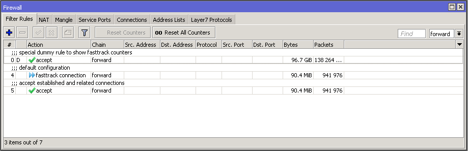
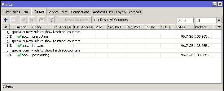
After adding the "FastTrack" rule special dummy rule appeared at the top of the list. This is not an actual rule, it is for visual information showing that some of the traffic is traveling FastPath and will not reach other firewall rules.
...
| Note |
|---|
The connection is FastTracked until a connection is closed, timed out or the router is rebooted. |
Requirements
...
- no mesh, metarouter interface configuration;
- sniffer, torch, and traffic generator is are not running;
- "/tool mac-scan" is not actively used;
- "/tool ip-scan" is not actively used;
- FastPath and Route cache is enabled under IP/Settings;
Packet flow for the visually impaired
The following document in DOCX format describes the diagram in a way optimized for visually impaired people. The descriptions are by Apex CoVantage care of Benetech. They are not being updated.
...