SXT kit series models:
SXT 4G kit
SXT LTE6 kit
SXT LTE kit-US
SXT LTE kit
SXT LTE6 kit (2023)
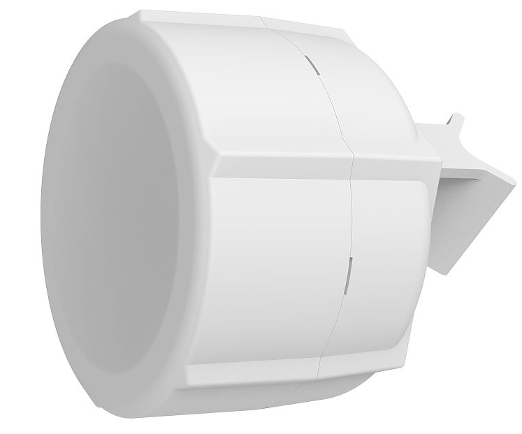
The SXT kit comes as a complete set and includes a built-in modem, connected to a built-in antenna. It has two 10/100 Ethernet connectors that support MDI-X auto-detection. There are two micro SIM card slots available, to switch between cell providers.
Safety Warnings
Before you work on any equipment, be aware of the hazards involved with electrical circuitry, and be familiar with standard practices for preventing accidents.
Ultimate disposal of this product should be handled according to all national laws and regulations.
All installation methods for mounting an access point on any wall surface are subject to the acceptance of local jurisdiction.
The Installation of the equipment must comply with local and national electrical codes.
This product is intended to be mounted outdoors on a pole. Please read the mounting instructions carefully before beginning installation. Failure to use the correct hardware and configuration or to follow the correct procedures could result in a hazardous situation for people and damage to the system.
Use only the power supply and accessories approved by the manufacturer, which can be found in the original packaging of this product.
Read the installation instructions before connecting the system to the power source.
We cannot guarantee that no accidents or damage will occur due to the improper use of the device. Please use this product with care and operate at your own risk!
In the case of device failure, please disconnect it from power. The fastest way to do so is by unplugging the power plug from the power outlet.
It is the customer's responsibility to follow local country regulations, including operation within legal frequency channels, output power, cabling requirements, and Dynamic Frequency Selection (DFS) requirements. All Mikrotik radio devices must be professionally installed.
This is a class A device. In a domestic environment, this product might cause radio interference in which case the user might be required to take adequate measures.
Exposure to Radio Frequency Radiation: This MikroTik equipment complies with the FCC, IC, and European Union radiation exposure limits set forth for an uncontrolled environment. This MikroTik device should be installed and operated no closer than 45 centimeters from your body, occupational user, or the general public.
First use
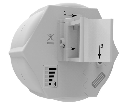
- Open the bottom lid.
- The IMEI number can be found on the case and packaging labels.
- Insert the SIM cards into the micro-SIM slots (SIM A slot is a default).
If using another slot, the configuration can be changed in RouterOS with the CLI command:
/system routerboard modem set sim-slot=down
After changing SIM slots, the LTE modem will be restarted. It can take some time (depending on the modem and board around 30 seconds) to fully initialize it, so make sure you test your modem.
https://help.mikrotik.com/docs/display/ROS/Dual+SIM+Application - Connect the device to the power source (see "Powering").
- Configure your device using a web browser through WebFig or the WinBox tool at https://mt.lv/WinBox;
- Access WebFig by opening http://192.168.188.1, and for WinBox, download the tool, navigate to the Neighbors tab, and click on the MAC address. The username is "admin" with no password (or, for some models, check user and wireless passwords on the sticker);
- Click the "Check for updates" button and update RouterOS to the latest version. Must have a valid SIM card inserted and active Internet connection;
- For a manual update of the device, visit the products page at https://mikrotik.com/products to find your product. The required packages are accessible under the "Support&Downloads" menu;
- Upload downloaded packages to the WebFig or WinBox "Files" menu and reboot the device;
- By upgrading your RouterOS software to the latest version, you can ensure optimal performance, stability, and security updates;
- Set up your router password.
All pre 7.1.4 versions of ROS will have the default IP set to 192.168.88.1, after an upgrade to 7.1.4 the default IP is set to 192.168.188.1.
Mounting
SXT is designed to be mounted on the pole, the package includes a mounting bracket and steel clamp.
- With the clip pointed forward, slide the mounting bracket into the rail on the bottom of the case, until the clip clicks into place.
- Guide the clamp through the opening in the bracket.
- Attach the unit to a pole, with the Ethernet port pointing downward.
- Use a PH2 screwdriver to tighten the rings when alignment is complete.
- Fix the Ethernet cable to the pole using zip ties, less than one meter from the unit, to avoid the cable being pulled out of the port.
- Check mounting angle and positioning.
When using both Ethernet ports, make sure to cut a wider cable opening in the plastic door. You can use pliers to tear out the plastic piece that is protecting the cable opening. When closing the plastic door, make sure to apply pressure, until it "clicks" into place.
The mounting and configuration of this device should be done by a qualified person.
When mounting on the wall, please ensure that the cable feed is pointing downwards.
The IPX rating scale of this device is IP54. We recommend using Cat6 shielded cables.
Warning! This equipment should be installed and operated with a minimum distance of 20 cm between the device and your body.
Grounding
The installation infrastructure (towers and masts), as well as the router itself, must be properly grounded. The device includes a grounding wire attachment screw behind the case door. Attach your grounding wire to the grounding screw, then attach the other end of the grounding wire to the grounded mast. This is to substantially reduce the risk of ESD and lightning damage.
Powering
The device accepts power from the Ethernet port:
- 12 - 57 V DC ⎓ passive and 802.3af/at PoE to the port ETH1.
The power consumption under maximum load can reach 5 W, with attachments 22 W.
Connecting to a PoE Adapter:
- Use an ethernet cable to connect the device to the PoE out (PoE+DATA or Data+Power) port of the PoE adapter.
- Plug the PoE adapter RJ45 connector into your local router, switch, or computer ethernet port.
- Connect the PSU DC plug into the PoE adapter, then connect PSU to the AC power source.
Configuration
Once logged in, we recommend clicking the "Check for updates" button in the QuickSet menu, as updating your RouterOS software to the latest version ensures the best performance and stability. For wireless models, please make sure you have selected the country where the device will be used, to conform to local regulations.
RouterOS includes many configuration options in addition to what is described in this document. We suggest starting here to get yourself accustomed to the possibilities: https://mt.lv/help. In case IP connection is not available, the WinBox tool (https://mt.lv/WinBox) can be used to connect to the MAC address of the device from the LAN side (all access is blocked from the Internet port by default).
For recovery purposes, it is possible to boot the device for reinstallation, see a section Reset button.
The default configuration is CPE RouterMode:
*LTE interface connected to providers network (WAN port);
*WAN port is protected by a firewall and enabled DHCP client.
LAN Configuration:
IP Address 192.168.88.1/24 is set on the bridge (LAN port)
All pre 7.1.4 versions of ROS will have the default IP set to 192.168.88.1, after an upgrade to 7.1.4 the default IP is set to 192.168.188.1.
DHCP Server enabled;
DNS: enabled.
WAN (gateway) Configuration:
gateway: lte1;
ip4 firewall: enabled;
NAT: enabled.
Extension slots and ports
- Two Ethernet ports that support automatic cross/straight cable correction (Auto MDI/X), so you can use either straight or cross-over cables for connecting to other network devices.
- The ETH2 port is capable of powering another RouterBOARD device with passive PoE (up to 57 V). The maximum output current is 600 mA when using less than 30 V to power this device and 400 mA when using more than 30 V.
- MiniPSIe slot.
- Two micro SIM slots.
- Integrated LTE module, supported bands depend on a region (check brochure).
SIM slot usage
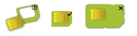
SIM card slot is designed to be used with Micro SIM cards.
Nano SIM cards have different thicknesses and usage with an adapter is not recommended.
Reset button
The reset button has three functions:
- Hold this button during boot time until the LED light starts flashing, release the button to reset RouterOS configuration (total 5 seconds);
- Keep holding for 5 more seconds, LED turns solid, release now to turn on CAP mode. The device will now look for a CAPsMAN server (total of 10 seconds);
- Or Keep holding the button for 5 more seconds until LED turns off, then release it to make the RouterBOARD look for Netinstall servers (total of 15 seconds);
Regardless of the above option used, the system will load the backup RouterBOOT loader if the button is pressed before power is applied to the device. Useful for RouterBOOT debugging and recovery.
Mode button
The action of the mode buttons can be configured from RouterOS software to execute any user-supplied RouterOS script. You can also disable this button. The mode button can be configured in RouterOS menu /system routerboard mode-button
Accessories
The package includes the following accessories that come with the device:
- ADAPT1_EU/US Switching Power Supply 24 V, 0.8 A, 19.2 W, 85.3%, VI, cable:150 cm Hor CMC;
- CLAMP1_Hose Clapmp SUS304 (Philips type; clamping diameter range 35-70 mm);
- POE1_POE Injector with shielded connector;
- BRAC1_SXT5D mounting;
Operating system support
The device supports RouterOS software version 7. The specific factory installed-version number is indicated in the RouterOS menu /system resource. Other operating systems have not been tested.
To troubleshoot any issues, visit the page provided and navigate to the dedicated troubleshooting section for detailed guidance and solutions: Troubleshooting articles
Federal Communication Commission Interference Statement
| Model | Contains FCCID |
|---|---|
| RBSXTR&R11e-4G | TV7R11E4G |
| RBSXTR&R11e-LTE6 | TV7R11ELTE6 |
| RBSXTR&R11e-LTE-US | TV7R11ELTE |
| RBSXTR&R11e-LTE | - |
![]()
This equipment has been tested and found to comply with the limits for a Class A digital device, pursuant to Part 15 of the FCC Rules. These limits are designed to provide reasonable protection against harmful interference in a commercial installation.
This equipment generates, uses, and can radiate radio frequency energy and, if not installed and used in accordance with the instruction manual, may cause harmful interference to radio communications. Operation of this equipment in a residential area is likely to cause harmful interference in which case the user will be required to correct the interference at his own expense.
FCC Caution: Any changes or modifications not expressly approved by the party responsible for compliance could void the user's authority to operate this equipment.
This device complies with Part 15 of the FCC Rules. Operation is subject to the following two conditions: (1) This device may not cause harmful interference, and (2) this device must accept any interference received, including interference that may cause undesired operation. This device and its antenna must not be co-located or operated in conjunction with any other antenna or transmitter.
IMPORTANT: Exposure to Radio Frequency Radiation.
This equipment complies with the FCC RF radiation exposure limits set forth for an uncontrolled environment. This equipment should be installed and operated with a minimum distance of 45 cm between the radiator and any part of your body.
For use of CBRS bands, the CBSD Category of the final Host equipment will be dependent on the power settings and antenna gain used.
Innovation, Science, and Economic Development Canada
| Model | Contains IC |
|---|---|
| RBSXTR&R11e-4G | 7442A-R11E4G |
| RBSXTR&R11e-LTE6 | 7442A-R11ELTE6 |
| RBSXTR&R11e-LTE-US | 7442A-R11ELTE |
| RBSXTR&R11e-LTE | - |
This device contains license-exempt transmitter(s)/receiver(s) that comply with Innovation, Science, and Economic Development Canada's license-exempt RSS(s). Operation is subject to the following two conditions:
- This device may not cause interference;
- This device must accept any interference, including interference that may cause undesired operation of the device.
L'émetteur/récepteur exempt de licence contenu dans le présent appareil est conforme aux CNR d'Innovation, Sciences et Développement économique Canada applicables aux appareils radio exempts de licence. L'exploitation est autorisée aux deux conditions suivantes:
- L'appareil ne doit pas produire de brouillage;
- L'appareil doit accepter tout brouillage radioélectrique subi, mźme si le brouillage est.
This Class A digital apparatus complies with Canadian ICES-003.
Cet appareil numérique de la classe [A] est conforme à la norme NMB-003 du Canada.
CAN ICES-003 (A) / NMB-003 (A)
IMPORTANT: Exposure to Radio Frequency Radiation.
This equipment complies with the IC radiation exposure limits set forth for an uncontrolled environment. This equipment should be installed and operated with a minimum distance of 45 cm between the radiator and any part of your body.
Cet equipement est conforme aux limites d'exposition au rayonnement IC definies pour un environnement non controle. Cet equipement doit etre installe et utilise a une distance minimale de 45 cm entre le radiateur et toute partie de votre corps.
UKCA marking

Eurasian Conformity Mark
Информация о дате изготовления устройства указана в конце серийного номера на его наклейке через дробь. Первая цифра означает номер года (последняя цифра года), две последующие означают номер недели.
Изготовитель: Mikrotikls SIA, Aizkraukles iela 23, Riga, LV-1006, Латвия, support@mikrotik.com. Сделано в Китае, Латвии или Литве. Cм. на упаковке.
Для получения подробных сведений о гарантийном обслуживании обратитесь к продавцу.
Продукты MikroTik, которые поставляются в Евразийский таможенный союз, оцениваются с учетом соответствующих требований и помечены знаком EAC, как показано ниже:

Norma Oficial Mexicana
EFICIENCIA ENERGETICA CUMPLE CON LA NOM-029-ENER-2017.
La operacion de este equipo esta sujeta a las siguientes dos condiciones:
- Es posible que este equipo o dispositivo no cause interferencia perjudicial y.
- Este equipo debe aceptar cualquier interferencia, incluyendo la que pueda causar su operacion no deseada.
Fabricante: Mikrotikls SIA, Unijas iela 2, Riga, LV-1039, Latvia.
País De Origen: Letonia; Lituania; China (Republica Popular); Estados Unidos De America; Mexico.
Por favor contacte a su distribuidor local para preguntas regionales específicas. La lista de importadores se puede encontrar en nuestra página de inicio – https://mikrotik.com/buy/latinamerica/mexico.
The National Commission for the State Regulation of Communications and Informatization by Ukraine
Виробник: Mikrotikls SIA, Unijas iela 2, Рига, Латвія, LV1039.
Справжнім Mikrotikls SIA заявляє, що маршрутизатор відповідає основним вимогам та іншим відповідним положенням директиви 2014/53/EC, а також суттєвим вимогам Технічного регламенту радіообладнання, затвердженого постановою Кабінету Міністрів України від 24 травня 2017 року № 355.
Для експлуатації в Україні необхідно отримати дозвіл на експлуатацію у порядку, затвердженому рішенням НКРЗІ від 01.11.2012 № 559, зареєстрованому в Міністерстві юстиції України 03.01.2013 за № 57/22589.
CE Declaration of Conformity
Manufacturer: Mikrotikls SIA, Unijas iela 2, Riga, Latvia, LV1039.
Hereby, Mikrotīkls SIA declares that the radio equipment type RouterBOARD is in compliance with Directive 2014/53/EU. The full text of the EU declaration of conformity is available at the following internet address: https://mikrotik.com/products![]()
GSM / WCDMA / LTE /
Operating Frequency / Maximum output power Betriebsfrequenz / maximale Ausgangsleistung Fréquence de fonctionnement / puissance de sortie maximale Frequenza operativa / massima potenza di uscita Frecuencia de funcionamiento / potencia de salida máxima Рабочая частота / максимальная выходная мощность | E-GSM-900 | 900 MHz / 33 dBm |
DCS-1800 | 1800 MHz 30 dBm | |
WCDMA Band I | 1922.4 MHz / 24 dBm ± 2.7 dB | |
WCDMA Band VIII | 882.4 MHz / 24 dBm ± 2.7 dB | |
LTE Band 1 (except SXT 4G kit) | 2100 MHz / 23dBm ± 2.7 dB | |
| LTE Band 3 | 1800 MHz / 23dBm ± 2.7 dB | |
| LTE Band 7 | 2600 MHz / 23dBm ± 2.7 dB | |
| LTE Band 8 (except SXT 4G kit) | 900 MHz / 23dBm ± 2.7 dB | |
| LTE Band 20 | 800 MHz / 23dBm ± 2.7 dB | |
| LTE Band 31 (only SXT 4G kit) | 450 MHz / 23dBm ± 2.7 dB | |
| LTE Band 38 (except SXT 4G kit) | 2600 MHz / 23dBm ± 2.7 dB | |
| LTE Band 40 | 2300 MHz / 23dBm ± 2.7 dB | |
| LTE Band 42 (only SXT 4G kit) | 3500 MHz / 23 dBm ± 3 dB | |
| LTE Band 43 (only SXT 4G kit) | 3700 MHz / 23 dBm ± 3 dB |
This MikroTik device meets Maximum LTE transmit power limits per ETSI regulations. For more detailed information see Declaration of Conformity above / Dieses MikroTik-Gerät erfüllt die maximalen LTE-Sendeleistung Grenzwerte gemäß ETSI-Bestimmungen. Weitere Informationen finden Sie oben unter Konformitätserklärung / Cet appareil MikroTik respecte les limites maximales de puissance de transmission LTE conformément aux réglementations ETSI. Pour plus d'informations, voir la déclaration de conformité ci-dessus / Questo dispositivo MikroTik è conforme ai limiti massimi di potenza di trasmissione LTE in conformità con le normative ETSI. Per ulteriori informazioni, consultare la dichiarazione di conformità sopra / Este dispositivo MikroTik cumple con los límites máximos de potencia de transmisión LTE de acuerdo con las regulaciones ETSI. Para obtener más información, consulte la declaración de conformidad anterior / Это устройство MikroTik соответствует максимальным пределам мощности передачи LTE в соответствии с правилами ETSI. Для получения дополнительной информации см. Декларацию соответствия выше.