Safety Warnings
Before you work on any equipment, be aware of the hazards involved with electrical circuitry, and be familiar with standard practices for preventing accidents.
Ultimate disposal of this product should be handled according to all national laws and regulations.
All installation methods for mounting an access point on any wall surface is subject to the acceptance of local jurisdiction.
The Installation of the equipment must comply with local and national electrical codes.
This product is intended to be mounted outdoors on a pole. Please read the mounting instructions carefully before beginning installation. Failure to use the correct hardware and configuration or to follow the correct procedures could result in a hazardous situation for people and damage to the system.
Use only the power supply and accessories approved by the manufacturer, and which can be found in the original packaging of this product.
Read the installation instructions before connecting the system to the power source.
We cannot guarantee that no accidents or damage will occur due to the improper use of the device. Please use this product with care and operate at your own risk!
In the case of device failure, please disconnect it from power. The fastest way to do so is by unplugging the power plug from the power outlet.
It is the customer's responsibility to follow local country regulations, including operation within legal frequency channels, output power, cabling requirements, and Dynamic Frequency Selection (DFS) requirements. All Mikrotik radio devices must be professionally installed.
Quickstart
Please follow these quick steps to set up your device:
- Mount unit in your desired place, please see Mounting paragraph.
- Slide off latch to access Ethernet port. Please see Opening latch section.
- Connect your PoE cable to the Ethernet port, please see Powering section.
- Set your computer IP configuration to automatic (DHCP).
- From your PC connect to the wireless network name which starts with "MikroTik".
- Once connected to the wireless network, open https://192.168.88.1
 in your web browser to start the configuration.
 - User name: admin and there is no password by default you will be logged in automatically to the Quick Set screen (or, for some models, check user and wireless passwords on the sticker).
- We recommend clicking the "Check for updates" button on the right side and updating your RouterOS software to the latest version to ensure the best performance and stability.
- To personalize your wireless network, SSID can be changed in the fields "Network Name".
- Choose your country on the left side of the screen in the field "Country", to apply country regulation settings.
- Set up your wireless network password in the field "WiFi Password" the password must be at least eight symbols.
- Set up your router password in the bottom field "Password" to the right and repeat it in the field "Confirm Password", it will be used to login next time.
- Click on the "Apply Configuration" to save changes.
MikroTik mobile app
Use the MikroTik smartphone app to configure your router in the field, or to apply the most basic initial settings for your MikroTik home access point.

- Scan QR code and choose your preferred OS.
- Install and open application.
- By default, the IP address and user name will be already entered.
- Click Connect to establish a connection to your device through a wireless network.
- Choose Quick setup and application will guide you through all basic configuration settings in a couple of easy steps.
- An advanced menu is available to fully configure all necessary settings.
Powering
The device accepts power from the PoE to the Ethernet port:
- Passive Power over Ethernet 8-30 V DC ⎓.
The power consumption under maximum load can reach 11,5 W.
Connecting to a POE Adapter:
- Connect the Ethernet cable from the device to the POE+DATA port of the POE adapter.
- Connect an Ethernet cable from your local network (LAN) to the POE adapter.
- Connect the power cord to the adapter, and then plug the power cord into a power outlet.
Configuration
We recommend clicking the "Check for updates" button and updating your RouterOS software to the latest version to ensure the best performance and stability. RouterOS includes many configuration options in addition to what is described in this document. We suggest starting here to get yourself accustomed to the possibilities: https://mt.lv/help. In case IP connection is not available, the Winbox tool (https://mt.lv/winbox) can be used to connect to the MAC address of the device from the LAN side (all access is blocked from the internet port by default). For recovery purposes, it is possible to boot the device from a network, see the section Reset button.
Extension slots and ports
- Gigabit Ethernet port, passive PoE on Ethernet port.
- 5 GHz wireless, supported protocol 802.11a/n/ac, antenna gain 24 (dBi).
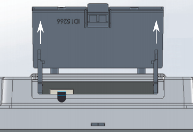
Opening latch
To access the Ethernet port and reset button, please open latch:
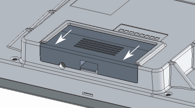
- Pull the latch out downwards from the device.
- Lift the latch, but do not remove them completely.
Front status LED behavior
RouterOS allows configuring each LED's activity the way that the user wishes. It is possible to configure the LEDs to display wireless strength, blink the LEDs on interface traffic activity and many other options. For further information please visit https://wiki.mikrotik.com/wiki/Manual:System/LEDS
Default factory configuration for this device:
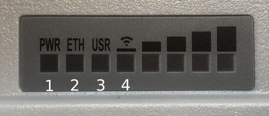
- Solid Blue – The device is powered on.
- Solid Green – Connected Ethernet port.
- Solid Green – User-defined LED.
- Solid Green – The set of five green LEDs, shows the signal strength.
Mounting
The device is designed to be used outdoors and mounted on the mast with all needed cables connecting through the latch of the unit.
Mounting and configuration of this device should be done by a qualified person.
When mounting on the mast, please ensure that the cable feed is pointing downwards.
The IP rating scale of this device is IP54. We recommend using Cat5/6 shielded cables.
Warning! This equipment should be installed and operated with a minimum distance of 30 cm between the device and your body. Operation of this equipment in the residential environment could cause radio interference.
The QRT box contains several parts that need to be assembled. Please follow this process:
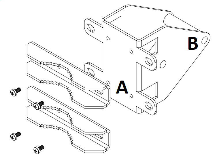
- Attach the two brackets (A) to the swivel adjuster (B), by using the four provided screws (use a PH1 screwdriver).
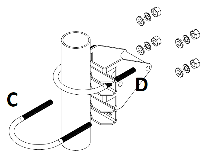
- Place the two U-bolts (C) around the mast or pole, and guide them through the holes on the swivel adjuster (D). Then, tighten the U-bolts, each with one regular washer, one spring washer, and one nut, as shown in the image to the right. All nuts need to be tightened using a size 10 (3/8 in) wrench. Maximum diameter of the pole can be up to 70 mm.
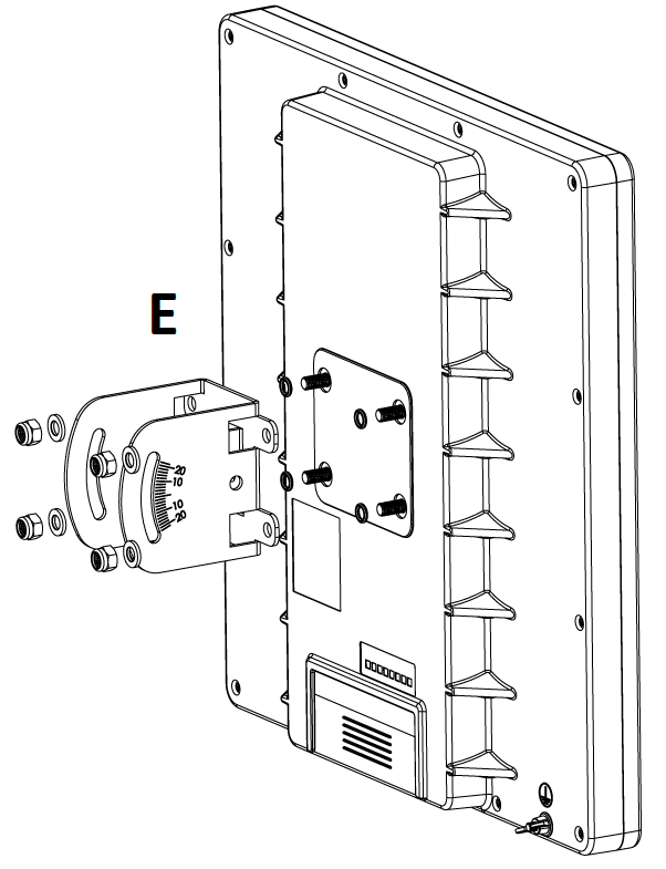
- Use the mounting bracket (E), and put it on to the back of the antenna. Install with one rubber ring, one washer, and one nut for each of the built-in bolts (in that order).
- Attach the swivel adjuster to the mounting bracket. Use the long bolt in the position (F). Put one regular washer, and one spring washer onto the shorter screws, then put them in positions (G). Do not tighten too much, as you need to adjust the antenna now.
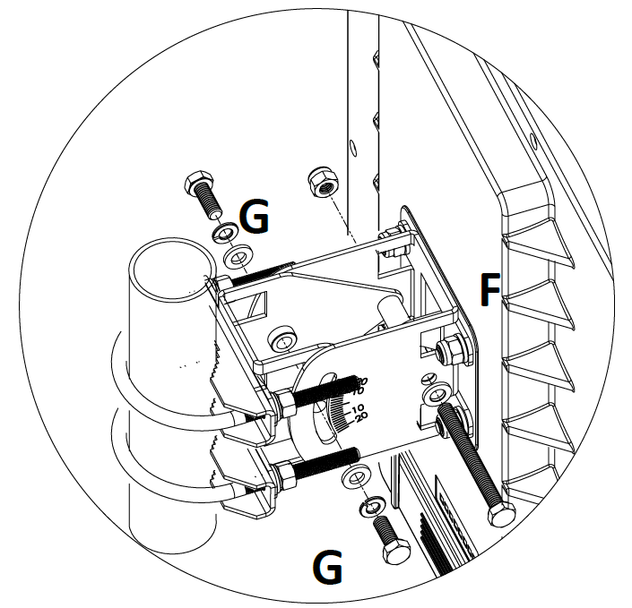
- Once antenna level and angle are adjusted according to the wireless signal in software, tighten all nuts. Note the degrees of angle for future reference.
Wind load
16 kg @ 40m/s, 9kg @ 30 m/s;
Grounding
The installation infrastructure (towers and masts), as well as the router itself, must be properly grounded. The device includes a grounding wire attachment screw on the backside of the unit. Attach your grounding wire to the grounding screw, then attach the other end of the grounding wire to the grounded mast, please see the picture:
Reset button
The reset button has three functions:
- Hold this button during boot time until the LED light starts flashing, release the button to reset RouterOS configuration (total 5 seconds).
- Keep holding for 5 more seconds, LED turns solid, release now to turn on CAP mode. The device will now look for a CAPsMAN server (total 10 seconds).
- Or Keep holding the button for 5 more seconds until LED turns off, then release it to make the RB911G-5HPacD-QRT look for Netinstall servers (total 15 seconds).
Regardless of the above option used, the system will load the backup RouterBOOT loader if the button is pressed before power is applied to the device. Useful for RouterBOOT debugging and recovery.
Accessories
Package includes accessories that come with the device:
- Montage elements: QRT U Bolt, Steel - Zinc plated, DIA 6 mm, U mast clamp, antenna mount.
- EU/US Switching Power Supply 24 V, 1.2 A, 30 W DC ⎓ cable:220 cm RA DC plug.
- K-QRT_Fastening set for QRT.
- ZCPOEC006-R2_Gigabit POE injector cable with shielded connector.
Operating System Support
The device supports RouterOS software with version number 6.46. at or above what is indicated in the RouterOS menu /system resource. Other operating systems have not been tested.
Specifications
For more information about this product, specifications, pictures, downloads, and test results please visit our web page: https://mikrotik.com/product/RB911G-5HPacD-QRT
Country List
AT | BE | BG | CY | CZ | DE | DK | EE | EL | ES | FI | FR | HR |
| |
IE | IT | LV | LT | LU | MT | NL | PL | PT | RO | SE | SI | SK | UK |
BFWA (Broadband Fixed Wireless Access) members noted in bold.
To avoid pollution of the environment, please separate the device from household waste and dispose of it in a safe manner, such as in designated waste disposal sites. Familiarize yourself with the procedures for the proper transportation of the equipment to the designated disposal sites in your area.
Federal Communication Commission Interference Statement
FCC ID:TV7RB922-5HPACTM![]()
This equipment has been tested and found to comply with the limits for a Class B digital device, pursuant to Part 15 of the FCC Rules. These limits are designed to provide reasonable protection against harmful interference in a residential installation.
This equipment generates, uses, and can radiate radio frequency energy and, if not installed and used in accordance with the instructions, may cause harmful interference to radio communications. However, there is no guarantee that interference will not occur in a particular installation. If this equipment does cause harmful interference to radio or television reception, which can be determined by turning the equipment off and on, the user is encouraged to try to correct the interference by one of the following measures:
- Reorient or relocate the receiving antenna.
- Increase the separation between the equipment and receiver.
- Connect the equipment into an outlet on a circuit different from that to which the receiver is connected.
- Consult the dealer or an experienced radio/TV technician for help.
FCC Caution: Any changes or modifications not expressly approved by the party responsible for compliance could void the user's authority to operate this equipment.
This device complies with Part 15 of the FCC Rules. Operation is subject to the following two conditions: (1) This device may not cause harmful interference, and (2) this device must accept any interference received, including interference that may cause undesired operation. This device and its antenna must not be co-located or operation in conjunction with any other antenna or transmitter.
IMPORTANT: Exposure to Radio Frequency Radiation.
This equipment complies with the FCC RF radiation exposure limits set forth for an uncontrolled environment. This equipment should be installed and operated with a minimum distance of 20 cm between the radiator and any part of your body.
Antenna Installation. WARNING: It is the installer's responsibility to ensure that when using the authorized antennas in the United States (or where FCC rules apply); only those antennas certified with the product are used. The use of any antenna other than those certified with the product is expressly forbidden in accordance to FCC rules CFR47 part 15.204. The installer should configure the output power level of antennas, according to country regulations and per antenna type. Professional installation is required for equipment with connectors to ensure compliance with health and safety issues.
Innovation, Science and Economic Development Canada
IC:7442A-9225HPACT
This device complies with Industry Canada's license-exempt RSS standard(s). Operation is subject to the following two conditions: (1) this device may not cause interference, and (2) this device must accept any interference, including interference that may cause undesired operation of the device.
Le présent appareil est conforme aux CNR d'Industrie Canada applicables aux appareils radio exempts de licence. L'exploitation est autorisée aux deux conditions suivantes : (1) l'appareil ne doit pas produire de brouillage, et (2) l'utilisateur de l'appareil doit accepter tout brouillage radioélectrique subi, même si le brouillage est susceptible d'en compromettre le fonctionnement.
This Class B digital apparatus complies with Canadian ICES-003.
Cet appareil numérique de la classe [B] est conforme à la norme NMB-003 du Canada.
CAN ICES-003 (B) / NMB-003 (B)
IMPORTANT: Exposure to Radio Frequency Radiation.
This equipment complies with the IC radiation exposure limits set forth for an uncontrolled environment. This equipment should be installed and operated with a minimum distance of 20 cm between the radiator and any part of your body.
Cet équipement est conforme aux limites d'exposition au rayonnement IC définies pour un environnement non contrôlé. Cet équipement doit être installé et utilisé à une distance minimale de 20 cm entre le radiateur et toute partie de votre corps.
UKCA marking

Eurasian Conformity Mark
Частотный диапазон | Мощность передатчика |
|---|---|
5150-5350 МГц, 5650-5850 МГц | ≤100 мВт |
*Доступные частотные каналы могут различаться в зависимости от модели продукта и сертификации.
Информация о дате изготовления устройства указана в конце серийного номера на его наклейке через дробь. Первая цифра означает номер года (последняя цифра года), две последующие означают номер недели.
Изготовитель: Mikrotikls SIA, Aizkraukles iela 23, Riga, LV-1006, Латвия, support@mikrotik.com. Сделано в Китае, Латвии или Литве. Cм. на упаковке.
Для получения подробных сведений о гарантийном обслуживании обратитесь к продавцу. Информация об импортерах продукции MikroTik в Российскую Федерацию: https://mikrotik.com/buy/europe/russia
Продукты MikroTik, которые поставляются в Евразийский таможенный союз, оцениваются с учетом соответствующих требований и помечены знаком EAC, как показано ниже:

Norma Oficial Mexicana
Rango de frecuencia (potencia de salida máxima): 5725-5850 MHz (30 dBm). Los canales de frecuencia disponibles pueden variar según el modelo y la certificación del producto.
EFICIENCIA ENERGETICA CUMPLE CON LA NOM-029-ENER-2017.
La operacion de este equipo esta sujeta a las siguientes dos condiciones:
- Es posible que este equipo o dispositivo no cause interferencia perjudicial y.
- Este equipo debe aceptar cualquier interferencia, incluyendo la que pueda causar su operacion no deseada.
Fabricante: Mikrotikls SIA, Brivibas gatve 214i, Riga, LV-1039, Latvia.
País De Origen: Letonia; Lituania; China (Republica Popular); Estados Unidos De America; Mexico.
Por favor contacte a su distribuidor local para preguntas regionales específicas. La lista de importadores se puede encontrar en nuestra página de inicio – https://mikrotik.com/buy/latinamerica/mexico.
The National Commission for the State Regulation of Communications and Informatization by Ukraine
Виробник: Mikrotikls SIA, Brivibas gatve 214i Рига, Латвія, LV1039.
Робоча частота (Максимальна вихідна потужність): 5150-5250 МГц (23 дБм), 5250-5350 МГц (20 дБм), 5470-5725 МГц (27 дБм).
Справжнім Mikrotikls SIA заявляє, що маршрутизатор відповідає основним вимогам та іншим відповідним положенням директиви 2014/53/EC, а також суттєвим вимогам Технічного регламенту радіообладнання, затвердженого постановою Кабінету Міністрів України від 24 травня 2017 року № 355.
Для експлуатації в Україні необхідно отримати дозвіл на експлуатацію у порядку, затвердженому рішенням НКРЗІ від 01.11.2012 № 559, зареєстрованому в Міністерстві юстиції України 03.01.2013 за № 57/22589.
CE Declaration of Conformity
Manufacturer: Mikrotikls SIA, Brivibas gatve 214i Riga, Latvia, LV1039.
Hereby, Mikrotīkls SIA declares that the radio equipment type RB911G-5HPacD-QRT is in compliance with Directive 2014/53/EU. The full text of the EU declaration of conformity is available at the following internet address: https://mikrotik.com/products![]()
Frequency bands terms of use
Frequency range (for applicable models) | Channels used | Maximum Output Power (EIRP) | Restriction |
5470-5725 MHz | 100 - 140 | 27 dBm | Without any restriction to use in all EU Member States |
* It is the customer's responsibility to follow local country regulations, including operation within legal frequency channels, output power, cabling requirements, and Dynamic Frequency Selection (DFS) requirements. All MikroTik radio devices must be professionally installed!