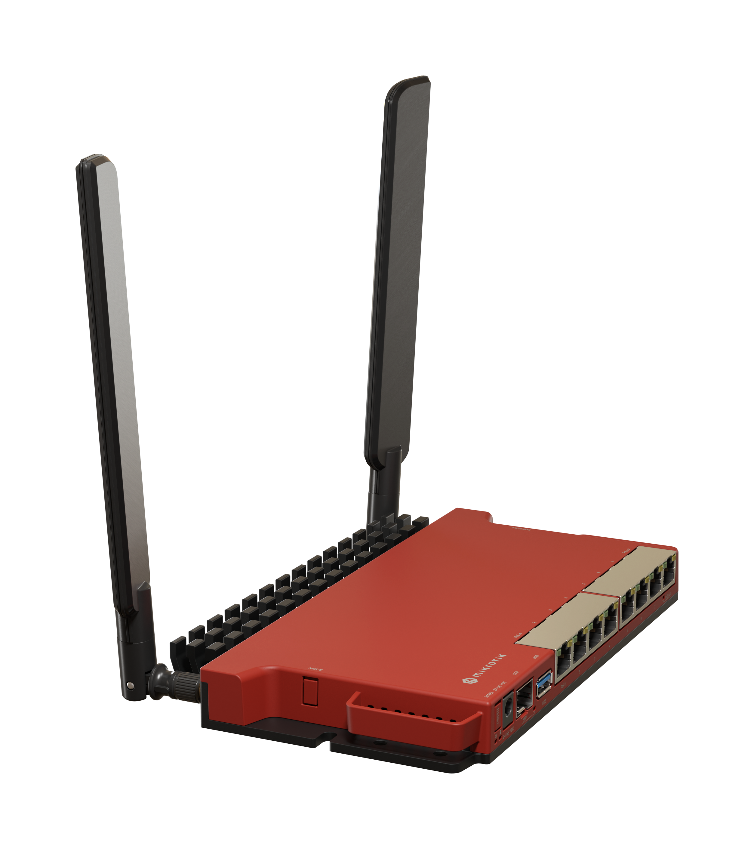
L009UiGS-2HaxD-IN
Safety Warnings
Before you work on any equipment, be aware of the hazards involved with electrical circuitry, and be familiar with standard practices for preventing accidents.
Ultimate disposal of this product should be handled according to all national laws and regulations.
The Installation of the equipment must comply with local and national electrical codes.
This unit is intended to be installed in the rackmount. Please read the mounting instructions carefully before beginning installation. Failure to use the correct hardware or to follow the correct procedures could result in a hazardous situation for people and damage to the system.
This product is intended to be installed indoors. Keep this product away from water, fire, humidity, or hot environments.
Use only the power supply and accessories approved by the manufacturer, which can be found in the original packaging of this product.
The socket-outlet shall be installed near the equipment and shall be easily accessible.
Read the installation instructions before connecting the system to the power source.
We cannot guarantee that no accidents or damage will occur due to the improper use of the device. Please use this product with care and operate at your own risk!
In the case of device failure, please disconnect it from power. The fastest way to do so is by unplugging the power plug from the power outlet.
It is the customer's responsibility to follow local country regulations, including operation within legal frequency channels, output power, cabling requirements, and Dynamic Frequency Selection (DFS) requirements. All Mikrotik devices must be professionally installed.
Setup
- Make sure your Internet service provider is allowing hardware change and will issue an automatic IP address;
- Connect your ISP cable to the first Ethernet port;
- Connect the device to the included power adapter;
- Connect your computer to the wireless network;
- The configuration can be done through the wireless network using a web browser or mobile app. Alternatively, you can use a WinBox configuration tool https://mt.lv/winbox;
- Open http://192.168.88.1 in your web browser to start configuration, user name: admin and there is no password by default (or, for some models, check user and wireless passwords on the sticker);
- Click the"Check for updates" button and update your RouterOS software to the latest version;
- For a manual update of the device, visit the products page at https://mikrotik.com/products to find your product. The required packages are accessible under the "Support&Downloads" menu;
- Upload downloaded packages to the WebFig or Winbox "Files" menu and reboot the device;
- Updating your RouterOS software to the latest version will ensure the best performance, stability, and security updates;
- Choose your country, to apply country regulation settings;
- Set up your wireless network password;
- Set up your router password.
Powering
The power consumption under maximum load can reach 47 W. The device accepts power from the power jack or from the first Ethernet port:
- Direct-input power jack (5.5 mm outside and 2 mm inside, female, pin positive plug) accepts 24-56 V DC.
- The First Ethernet port accepts Power over Ethernet 802.3af/at.
- The 2-pin terminal on the side accepts 24-56 V DC.
Connecting to a POE Adapter:
- Connect the Ethernet cable from the device to the POE port of the POE adapter.
- Connect an Ethernet cable from your LAN to the LAN port of the POE adapter, please mind arrows for data and power flow.
- Connect the power cord to the adapter, and then plug the power cord into a power outlet.
Configuration
Once logged in, we recommend clicking the "Check for updates" button in the QuickSet menu. Updating your RouterOS software to the latest version ensures optimal performance and stability. For wireless models, please make sure you have selected the country where the device will be used, to conform to local regulations.
RouterOS includes many configuration options in addition to what is described in this document. We suggest starting here to get yourself accustomed to the possibilities: https://mt.lv/help. In case an IP connection is not available, the Winbox tool (https://mt.lv/winbox) can be used to connect to the MAC address of the device from the LAN side (all access is blocked from the Internet port by default).
For recovery purposes, it is possible to boot the device for reinstallation, see section Buttons and jumpers.
Mounting
The device is designed to use indoors and it can be mounted on the wall, or it can be placed on the desktop.
- Find the designed mounting holes on both sides of the device, as shown in the picture;
- Use provided screws to secure the device to the wall;
- Based on the wall material you can use a drill bit and provided dowels.
The device has no protection from water contamination, please ensure the placement of the device in a dry and ventilated environment.
We recommend Cat6 cables for our devices.
The mounting and configuration of this device should be done by a qualified person.
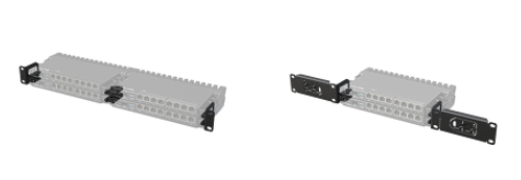
Rackmount
If desired placement is rackmount, additional brackets can be purchased separately:
RB5009/L009 rackmount kit K-79
Extension slots and ports
- Product code L009UiGS-2HaxD-IN
- CPU IPQ-5018 800 MHz
- CPU architecture ARM
- CPU core count 2
- Size of RAM 512 MB
- RAM type DDR3L
- Storage 128 MB, NAND
- Number of 1G Ethernet ports 8
- Number of 2.5G SFP ports 1
- USB port 1 (3.0 type A)
- PoE-in Ether1
- PoE-out Ether8
- Serial console port RJ45
- Operating system RouterOS (License level 5)
- Switch chip model 88E6190
- Wireless interface model IPQ-5018 (2.4 GHz)
- Wireless 2.4 GHz 802.11b/g/n/ax dual-chain
- Wireless antenna max gain 2.4 GHz (4 dBi)
- Dimensions 220 x 125 x 22 mm
- Operating temperature -40°C to +70°C
- IP 20
Buttons and jumpers
The RouterBOOT reset button has the following functions. Press the button and apply the power, then:
- Release the button when the green LED starts flashing, to reset the RouterOS configuration to defaults.
- Press the Reset button and power on your device (wait until the USR/SFP led is blinking then stable "On", and when the USR/SFP led is "Off" - release the Reset button) - the device is booting in bootp mode to reinstall RouterOS using Netinstall. (required for reinstalling RouterOS over the network using Ether1).
Regardless of the above option used, the system will load the backup RouterBOOT loader if the button is pressed before power is applied to the device. Useful for RouterBOOT debugging and recovery.
LED
- Hidden Green LED behind the Reset button is a USER LED
- Blue LED 1 is the DC1 Power LED
- Blue LED 2 is the DC2 Power LED
- Green SFP LED is an SFP port link and activity LED
- Ethernet RJ45 Green LEDs are Ethernet port link 1Gbps and activity LEDs
- Ethernet RJ45 Port 1 Orange LED is PoE-in status LED
- Ethernet RJ45 Port 2-8 Orange LEDs only - 100Mbps
Accessories
The package includes the following accessories that come with the device:
- ADAPT1_EU/US Switching Power Supply 24V 1.5A 36W
- SET1_ K-55 fastening set
- PAD1_ 4 pcs Pad D=7; H=1.5 mm, one side adhesive 3M988T
Please visit wiki pages for the MikroTik SFP module compatibility table: https://help.mikrotik.com/docs/spaces/ROS/pages/220233794/MikroTik+wired+interface+compatibility
Operating system support
The device supports RouterOS software version 7. The specific factory-installed version number is indicated in the RouterOS menu /system resource. Other operating systems have not been tested.
To avoid pollution of the environment, please separate the device from household waste and dispose of it in a safe manner, such as at designated waste disposal sites. Familiarize yourself with the procedures for the proper transportation of the equipment to the designated disposal sites in your area.