Introduction
One of the protocols that is widely used in IoT architectures is called Modbus.
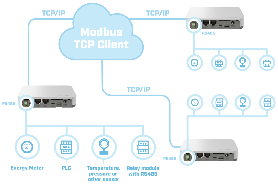
You can find more information about this protocol following this link. The feature allows KNOT to act as a TCP bridge and read data from Modbus-supported devices connected to a 2-pin terminal block on the board. Modbus clients (slaves) can access the data from the Modbus server (master - KNOT) using the 502/TCP port.
The Modbus-supported device should be connected to the RS485 port. A two-wire connection (A+/B-) is supported by the device.
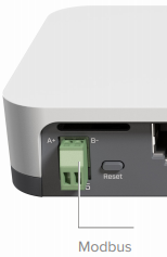
It is important to note that both pins should not be mixed up. Inverting the "A" and "B" connections (incorrect polarisation) will result in communication failure.
Another thing to keep in mind is Modbus cable distance. If the cable length is less than 50 meters - there should be no issues. If 50+ meters cable is used, 120 Ohm termination resistance should be installed at the end of the cable.
Configuration
Once the board is connected to the Modbus device, the only thing that needs to be altered/checked in the settings is the "Modbus" port configuration:
|
By default, a port with the name "modbus" is assigned to the Modbus service, but the service itself is disabled. In order to activate the "Modbus" service, you need to issue the command, as shown below:
|
Additionally, since the Modbus clients communicate with the Modbus server using TCP(502)/IP protocol, you need to make sure that the IP address is configured accordingly and that this IP+502 TCP port is accessible from the outside (in case "slave" devices are connecting from the WAN side). You can find information on how to configure the firewall using the firewall manual.
Modbus clients
In order to send commands to the end-device, Modbus Client should be used. You can use any Modbus Client software (there are plenty on the internet) or it can be easily written/configured in Python. Run the software and make sure that TCP/IP (502 port) connection gets established.
Modbus TCP packet structure
The query packet consists of Transaction ID, Protocol, Length, Unit ID, Function Code and Function Parameters fields and the maximum size is 260 bytes.
- Transaction ID - integer from 0 to 65535 used to identify the answer to the specific query;
- Protocol - 0x0000 stands for Modbus;
- Length - shows how many bytes will follow the Length field;
- Unit ID - usually called "Device address", 0x00-0xff. Each end-device in the specific system should have a unique ID;
- Function Code - describes which function will be called. Each device has multiple registers and these functions are used to interact with the registers. Codes are defined by the standards but the manufacturers can also implement their own functions with specific codes;
- Function Parameters - usually specifies register address, data length and data to be written in case the "write" function is used.
Default Unit ID, Function Codes and Parameters can be found in the datasheet for the specific product. Answer messages are structured similarly and should be described in the product-datasheet as well.
Reading MODBUS data using RouterOS
As of right now, you can only read function code 3 output values. So if the connected MODBUS device can give a response to a Function Code 3 (read Analog Output Holding Registers) command → you can get/print it in the RouterOS terminal, like so:
[admin@device] /iot modbus read-holding-registers slave-id=0x03 num-regs=0x1 reg-addr=0x0 as-value once
2349
[admin@device] /iot modbus read-holding-registers slave-id=0x03 num-regs=0x5 reg-addr=0x0 as-value once
2353;3;500;75;38
Parameters that can vary are "reg-addr","num-regs" and "slave-id". All of them depend on what values are supported by the MODBUS-connected device.