Summary
Controller Bridge (CB) and Port Extender (PE) is an IEEE 802.1BR standard implementation in RouterOS for CRS3xx series switches. It allows virtually extending the CB ports with a PE device and manage these extended interfaces from a single controlling device. Such configuration provides a simplified network topology, flexibility, increased port density and ease manageability. An example of Controller Bridge and Port Extender topology can be seen below.
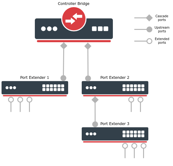
The Controller Bridge establishes communication with the Port Extender through a cascade port. Similarly, the Port Extender will communicate with the Controller Bridge only through an upstream port. On a PE device, control ports must be configured and only one port (closest to the CB) will act as an upstream port, other control ports can act as a backup for upstream port or even cascade port for switches connected in series (e.g. Port Extender 2 and 3 in the image above). Cascade and upstream ports are used to transmit and receive control and network traffic. Extended ports are interfaces that are controlled by the CB device and they are typically connected to the end hosts. Extended ports only transmit and receive network traffic.
See supported features for each switch model below.
| Model | Controller Bridge | Port Extender |
|---|---|---|
| netPower 15FR (CRS318-1Fi-15Fr-2S) | - | + |
| netPower 16P (CRS318-16P-2S+) | - | + |
| CRS326-24G-2S+ (RM/IN) | - | + |
| CRS328-24P-4S+ | - | + |
| CRS328-4C-20S-4S+ | - | + |
| CRS305-1G-4S+ | - | + |
| CRS309-1G-8S+ | + | + |
| CRS317-1G-16S+ | + | + |
| CRS312-4C+8XG | + | + |
| CRS326-24S+2Q+ | + | + |
| CRS354-48G-4S+2Q+ | + | + |
| CRS354-48P-4S+2Q+ | + | + |
Quick setup
In this example, we will create a Controlling Bridge (e.g. a CRS317-1G-16S+ switch) that will connect to a single Port Extender (e.g. a CRS326-24G-2S+ switch) through an SFP+1 interface.
First, configure a bridge with enabled VLAN filtering on a CB device:
/interface bridge
add name=bridge1 vlan-filtering=yes
On the same device, configure a port that is connected to the PE device and will act as cascade port:
/interface bridge port-controller
set bridge=bridge1 cascade-ports=sfp-sfpplus1 switch=switch1
Last, on a PE device, simply configure a control port, which will be selected as an upstream port:
/interface bridge port-extender
set control-ports=sfp-sfpplus1 switch=switch1
Once PE and CB devices are connected, all interfaces that are on the same switch group (except for control ports) will be extended and can be further configured on a CB device. An automatic bridge port configuration will be applied on the CB device which adds all extended ports in a single bridge, this configuration can be modified afterward.
In order to exclude some port from being extended (e.g. for out-of-band management purposes), additionally, configure excluded-ports property.
Make sure not to include the cascade-ports and control-ports in any routing or bridging configurations. These ports are recommended only for a CB and PE usage.
Packet flow and forwarding
ETAG usage, packet flooding (broadcast, multicast, unicast), unicast forwarding, learning.
Controller Bridge settings and monitoring
This section describes the Controller Bridge settings and monitoring options.
Sub-menu: /interface bridge port-controller
Property | Description |
|---|---|
| bridge (name; Default: none) | The bridge interface where ports will be extended. The CB will only enable when bridge and switch properties are specified, otherwise, it will be in a disabled state. |
| cascade-ports (interfaces; Default: none) | Interfaces that will act as cascade ports. A bonding interface with 802.3ad or balance-xor mode is also supported. |
| switch (name; Default: none) | The switch that will act as the CB and ensure the control and network traffic. The CB will only enable when bridge and switch properties are specified, otherwise, it will be in a disabled state. |
After CB and PE devices are configured and connected, each PE device will be automatically visible on the device menu, use print and monitor commands to see more details.
[admin@Controller] > interface bridge port-controller device print
Flags: I - inactive
 0   name="pe1" pe-mac=64:D1:54:EB:AE:BC descr="MikroTik RouterOS 6.48beta35 (testing) CRS328-24P-4S+" control-ports=pe1-sfpplus1,pe1-sfpplus2

 1   name="pe2" pe-mac=64:D1:54:C7:3A:58 descr="MikroTik RouterOS 6.48beta35 (testing) CRS326-24G-2S+" control-ports=pe2-sfpplus1
[admin@Controller] > interface bridge port-controller device monitor pe2
                 name: pe2
               status: active
  connected-via-ports: sfp-sfpplus1==pe1-sfpplus1,pe1-sfpplus2==pe2-sfpplus1
   connected-via-devs: controller,pe1
Sub-menu: /interface bridge port-controller device
Property | Description |
|---|---|
| connected-via-devs (name) | Shows the connected devices in the path from PE to CB. |
| connected-via-ports (name) | Shows the connection path from PE to CB. |
| control-ports (interfaces) | PE device control ports. |
| descr (name) | Short PE device description. |
| name (name) | Automatically assigned PE device name. |
| pe-mac (MAC address) | PE device MAC address. |
| status (active | inactive) | PE device status. |
Additionally, each PE device port can be monitored on the port menu, use print and monitor commands to see more details.
[admin@Controller] > interface bridge port-controller port print where !disabled
Flags: I - inactive, X - disabled, R - running, U - upstream-port, C - cascade-port
 #    NAME                                   DEVICE
 0 I  pe1-ether1                             pe1
 1 R  pe1-ether2                             pe1
 2 R  pe1-ether3                             pe1
 3 R  pe1-ether4                             pe1
 4  U pe1-sfpplus1                           pe1
 5 RC pe1-sfpplus2                           pe1
 6 I  pe2-ether1                             pe2
 7 R  pe2-ether2                             pe2
 8 R  pe2-ether3                             pe2
 9 R  pe2-ether4                             pe2
10  U pe2-sfpplus1                           pe2
[admin@Controller] > interface bridge port-controller port monitor [find where !disabled]
           name: pe1-ether1 pe1-ether2 pe1-ether3 pe1-ether4 pe1-sfpplus1 pe1-sfpplus2 pe2-ether1 pe2-ether2 pe2-ether3 pe2-ether4 pe2-sfpplus1
         status: unknown    link-ok    link-ok    link-ok    no-link      link-ok      unknown    link-ok    link-ok    link-ok    no-link
           rate:            1Gbps      1Gbps      1Gbps      10Gbps       10Gbps                  1Gbps      1Gbps      1Gbps      10Gbps
    port-status: not-added  ok         ok         ok         ok           ok           not-added  ok         ok         ok         ok
           pcid:            457        458        459        480          481                     509        510        511        532
Sub-menu: /interface bridge port-controller port
Property | Description |
|---|---|
| device (name) | Automatically assigned PE device name. |
| name (name) | Automatically assigned PE port name. |
| pcid (integer) | Automatically assigned port identifier. |
| port-status (dev-inactive | not-added | ok) | PE port status. |
| rate (bps) | Data rate of the connection. |
| status (link-ok | no-link | unknown) | PE port link status. |
List of available configuration properties, monitoring options. Neighbor discovery changes (how PE and CB discover each other using LLDP TLVs, on PE control-ports discovery is automatically enabled and disabled on extended ports (they get controlled by the CB settings), on CB cascade ports discovery is automatically enabled), automatic bridge port configuration, how to apply and remove (device remove, port remove, other settings where an extended interface is configured will stay and should be removed manually) the configuration for extender ports (PE can even be disconnected and still apply configuration on CB), extended port naming, ECP protocol for control information between PE and CB.
Port Extender settings
This section describes the Port Extender settings.
Sub-menu: /interface bridge port-extender
Property | Description |
|---|---|
| control-ports (interfaces; Default: none) | Interfaces that will either connect to the CB (upstream port) or connect other PE devices in series (cascade port). A bonding interface with 802.3ad or balance-xor mode is also supported. |
| excluded-ports (interfaces; Default: none) | Interfaces that will not be extended. |
| switch (name; Default: none) | The switch that will act as the extender and ensure the control and network traffic. The PE will only enable when this property is specified, otherwise, it will be in a disabled state. |
Limitations
Known limitation (e.g. only single CB possible, ingress-filtering on extended ports) and recommendations (e.g use control/cascade ports only for communication between CB and PE, do not use these ports for bridging or routing)
Examples
Some most basic and commonly used examples