Spanning Tree Protocol
The purpose of spanning tree protocol is to provide the ability to create loop-free Layer 2 topologies while having redundant links. While connecting multiple bridges or just cross-connecting bridge ports, it's possible to create network loops that can severely impact the stability of the network. Spanning tree protocol aims to resolve this problem by introducing the concept of the root bridge, all bridges in the same Layer 2 domain will exchange information about the shortest path to the root bridge. Afterward, each bridge will negotiate which ports to use to reach the root bridge. This information exchange is done with the help of Bridge Protocol Data Units (BPDUs). STP will disable certain ports for each bridge in order to avoid loops, while still ensuring that all bridges can communicate with each other. For an in-depth description of protocol please refer to 802.1w.
As a best practice, it is always recommended to manually set up each bridge's priority, port priority, and port path cost to ensure proper Layer2 functionality at all times. Leaving STP related values to defaults are acceptable for a network that consists of 1 to 2 bridges running with (R/M)STP enabled, but it is highly recommended to manually set these values for larger networks. Since STP elects a root bridge and root ports by checking STP related values from bridges over the network, then leaving STP settings to automatic may elect an undesired root bridge and root ports and in case of a hardware failure can result in an inaccessible network.
Monitoring
You can check the STP status of a bridge by using the /interface bridge monitor command, for example:
/interface bridge monitor bridge
                  state: enabled
    current-mac-address: 64:D1:54:D9:27:E6
            root-bridge: yes
         root-bridge-id: 0x3000.64:D1:54:D9:27:E6
         root-path-cost: 0
              root-port: none
             port-count: 5
  designated-port-count: 5
Note that the root bridge doesn't have any root ports, only designated ports.
You can check the STP status of a bridge port by using the /interface bridge port monitor command, for example:
/interface bridge port monitor 2
               interface: ether3
                  status: in-bridge
             port-number: 3
                    role: root-port
               edge-port: no
     edge-port-discovery: yes
     point-to-point-port: yes
            external-fdb: no
            sending-rstp: yes
                learning: yes
              forwarding: yes
          root-path-cost: 10
       designated-bridge: 0x3000.64:D1:54:D9:27:E6
         designated-cost: 0
  designated-port-number: 4
        hw-offload-group: switch1
Note that root-bridge-id consists of the bridge priority and the bridge's MAC address, for non-root bridges the root bridge will be shown as designated-bridge. One port can have one role in an STP enabled network, below is a list of possible port roles:
- root-port - port that is facing towards the root bridge and will be used to forward traffic from/to the root bridge.
- alternate-port - port that is facing towards root bridge, but is not going to forward traffic (a backup for root port).
- backup-port - port that is facing away from the root bridge, but is not going to forward traffic (a backup for non-root port).
- designated-port - port that is facing away from the root bridge and is going to forward traffic.
- disabled-port - disabled or inactive port.
When using bridges that are set to use 802.1Q as EtherType, they will send out BPDUs to 01:80:C2:00:00:00, which are used by MSTP, RSTP, and STP. When using 802.1ad as bridge VLAN protocol, the BPDUs are not compatible with 802.1Q bridges and they are sent to 01:80:C2:00:00:08. (R/M)STP will not function properly if there are different bridge VLAN protocols across the Layer2 network.
STP and RSTP
STP and Rapid STP are used widely across many networks, but almost all networks have switched over using only RSTP since of its benefits. STP is a very old protocol and has a convergence time (the time needed to fully learn network topology changes and to continue properly forwarding traffic) of up to 50 seconds. RSTP has a lot of smaller convergence time, a few seconds or even a few milliseconds. It is recommended to use RSTP instead of STP since it is a lot faster and is also backward compatible with STP. One of the reasons why RSTP is faster is because of reduced possible port states, below is a list of possible STP port states:
- Forwarding - port participates in traffic forwarding and is learning MAC addresses, is receiving BPDUs.
- Listening - port does not participate in traffic forwarding and is not learning MAC addresses, is receiving BPDUs.
- Learning - port does not participate in traffic forwarding but is learning MAC addresses.
- Blocking - port is blocked since it is causing loops but is receiving BPDUs.
- Disabled - port is disabled or inactive.
In RSTP the disabled, listening and blocking port states are replaced with just one state called the Discarding state:
- Forwarding - port participates in traffic forwarding and is learning MAC addresses, is receiving BPDUs (forwarding=yes).
- Learning - port does not participate in traffic forwarding but is learning MAC addresses (learning=yes).
- Discarding - port does not participate in traffic forwarding and is not learning MAC addresses, is receiving BPDUs (forwarding=no).
In STP connectivity between bridges is determined by sending and receiving BPDUs between neighbor bridges. Designated ports are sending BPDUs to root ports. If a BPDU is not received 3 times the HelloTime in a row, then the connection is considered as unavailable and network topology convergence will commence. It is possible for STP to reduce the convergence time in certain scenarios by reducing the forward-delay timer, which is responsible for how long can the port be in the learning/listening state.
In RouterOS, it is possible to specify which bridge ports are edge ports. Edge ports are ports that are not supposed to receive any BPDUs, this is beneficial since this allows STP to skip the learning and the listening state and directly go to the forwarding state. This feature is sometimes called PortFast· You can leave this parameter to the default value, which is auto, but you can also manually specify it, you can set a port as edge port manually for ports that should not have any more bridges behind it, usually these are access ports.
Default values
When creating a bridge or adding a port to the bridge the following are the default values that are assigned by RouterOS:
- Default bridge priority: 32768 / 0x8000
- Default bridge port path cost: 10
- Default bridge port priority: 0x80
- BPDU message age increment: 1
- HelloTime: 2
- Default max message age: 20
RouterOS does not change port path cost based on the link speed, for 10M, 100M, 1000M, and 10000M link speeds the default path cost value when a port is added to a bridge are always 10. The age of a BPDU is determined by how many bridges have the BPDU passed times the message age since RouterOS uses 1 as the message age increment, then the BPDU packet can pass as many bridges as specified in the max-message-age parameter. By default this value is set to 20, this means that after the 20th bridge the BPDU packet will be discarded and the next bridge will become a root bridge, note that if max-message-age=20on is set, then it is hard to predict which ports will be the designated port on the 21st bridge and may result in traffic not being able to be forwarded properly.
In case bridge filter rules are used, make sure you allow packets with DST-MAC address 01:80:C2:00:00:00 since these packets carry BPDUs that are crucial for STP to work properly.
Election process
To properly configure STP in your network you need to understand the election process and which parameters are involved in which order. In RouterOS the root bridge will be elected based on the smallest priority and the smallest MAC address in this particular order:
- Bridge priority (lowest)
- Bridge MAC address (lowest)
In RouterOS root ports are elected based on lowest Root port path cost, lowest bridge identifier, and lowest bridge port ID in this particular order:
- Root port path cost (lowest)
- Bridge identifier (lowest)
- Bridge port ID (lowest)
First, when the device considers which of its ports to elect as the root port, it will check the root path cost seen by its ports. If root path cost is the same for two or more ports then the Bridge identifier of the upstream device will be checked and port connected to the lowest bridge identifier will become the root port. If the same bridge identifier is seen on two or more ports, then the Bridge port ID of the upstream device will be checked.
Explanation of attributes:
Root path cost, all bridges have a Root Path Cost. Root bridge has a root path cost of 0. For all other Bridges, it is the sum of the Port Path Costs on the least-cost path to the Root Bridge. You can modify local port path cost under "/interface bridge port".
Bridge identifier is a combination of "bridge priority" and "bridge MAC", configurable under "/interface bridge"
Bridge port ID is a combination of "unique ID" and "bridge port priority", the unique ID is automatically assigned to bridge port upon adding it to the bridge, it cannot be edited. It can be seen in WinBox under "Bridge Port" "Port Number" column, or with "/interface bridge port monitor", as "port-number".
Make sure you are using path cost and priority on the right ports. For example, setting path cost on ports that are in a root bridge has no effect, only port priority has an effect on them. Root path cost has an effect on ports that are facing towards the root bridge and port priority has an effect on ports that are facing away from the root bridge. And bridge identifier doesn’t impact the device's own root port election, instead, it affects the root port election for downstream devices.
In RouterOS it is possible to set any value for bridge priority between 0 and 65535, the IEEE 802.1W standard states that the bridge priority must be in steps of 4096. This can cause incompatibility issues between devices that do not support such values. To avoid incompatibility issues, it is recommended to use only these priorities: 0, 4096, 8192, 12288, 16384, 20480, 24576, 28672, 32768, 36864, 40960, 45056, 49152, 53248, 57344, 61440.
Examples
General STP enabled network example
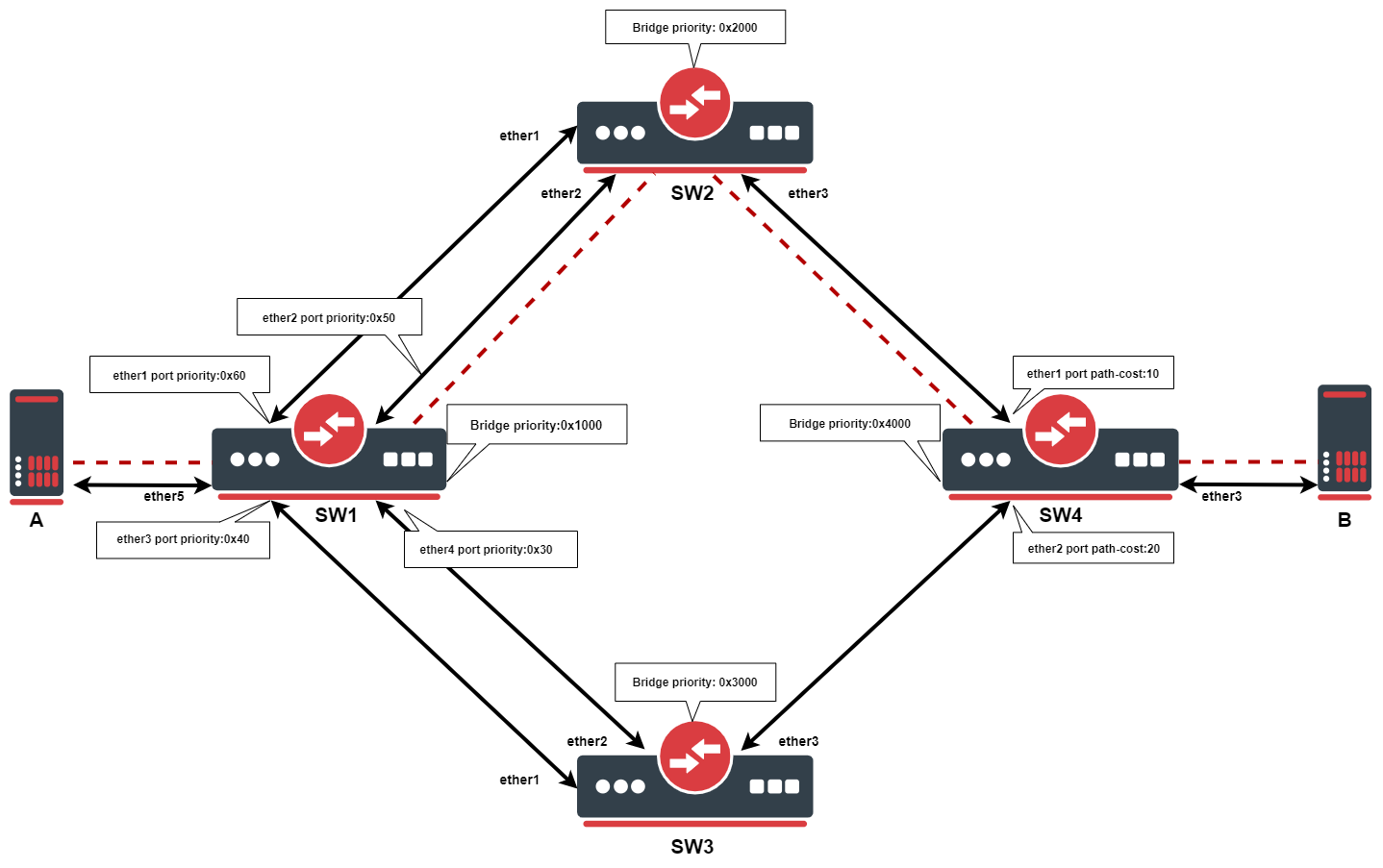
In this example, we want to ensure Layer2 redundancy for connections from ServerA to ServerB. If a port is connected to a device that is not a bridge and not running (R)STP, then this port is considered as an edge port, in this case ServerA and ServerB is connected to an edge port. This is possible by using STP in a network. Below are configuration examples for each switch.
- Configuration for SW1:
/interface bridge
add name=bridge priority=0x1000
/interface bridge port
add bridge=bridge interface=ether1 priority=0x60
add bridge=bridge interface=ether2 priority=0x50
add bridge=bridge interface=ether3 priority=0x40
add bridge=bridge interface=ether4 priority=0x30
add bridge=bridge interface=ether5
- Configuration for SW2:
/interface bridge
add name=bridge priority=0x2000
/interface bridge port
add bridge=bridge interface=ether1
add bridge=bridge interface=ether2
add bridge=bridge interface=ether3
- Configuration for SW3:
/interface bridge
add name=bridge priority=0x3000
/interface bridge port
add bridge=bridge interface=ether1
add bridge=bridge interface=ether2
add bridge=bridge interface=ether3
- Configuration for SW4:
/interface bridge
add name=bridge priority=0x4000
/interface bridge port
add bridge=bridge interface=ether1
add bridge=bridge interface=ether2 path-cost=20
add bridge=bridge interface=ether3
In this example, SW1 is the root bridge since it has the lowest bridge priority. SW2 and SW3 has ether1,ether2 connected to the root bridge and ether3 is connected to SW4. When all switches are working properly, the traffic will be flowing from ServerA through SW1_ether2, through SW2, through SW4 to ServerB. In the case of SW1 failure, the SW2 becomes the root bridge because of the next lowest priority. Below is a list of ports and their role for each switch:
- root-port - SW2_ether2, SW3_ether2, SW4_ether1
- alternate-port - SW2_ether1, SW3_ether1, SW4_ether2
- designated-port - SW1_ether1, SW1_ether2, SW1_ether3, SW1_ether4, SW1_ether5, SW2_ether3, SW2_ether3, SW4_ether3
Note: By the 802.1W recommendations, you should use bridge priorities in steps of 4096. To set a recommended priority it is more convenient to use hexadecimal notation, for example, 0 is 0x0000, 4096 is 0x1000, 8192 is 0x2000 and so on (0..F).