Quickstart
The configuration is the same as PTP Bridge in AP mode, except that wireless mode is set to ap_bridge for PTMP setups. The router can be accessed directly using MAC address. If the device is connected to the network with enabled DHCP server, configured DHCP client on the bridge interface will get the IP address, that can be used to access the router.
Please follow these quick steps to set up your device:
- Open the upper cover (see "NetMetal ac²#Removing upper and bottom covers");
- Connect an external antenna to the SMA connector (see "NetMetal ac²#Antenna usage");
- Open the bottom cover (see "NetMetal ac²#Removing upper and bottom covers");
- Connect your PC with Ethernet cable to the Ethernet port of the device, or connect your ISP cable to the device.
- Connect the device to the power source (see "NetMetal ac²#Powering");
- Open network connections on your PC and search for MikroTik wireless network and connect to it;
- The configuration can be done through the wireless network using a WinBox configuration tool https://mt.lv/winbox;
- Once connected to the wireless network, open Winbox and click on the "Neighbors" to find the device.
- Click on the MAC address, user name: admin and there is no password, click Connect.
- Please update the device to the latest version, use the "Check for updates" button if you are connected to the ISP and have an active internet connection. If you are connecting to the device using Winbox, please go https://mikrotik.com/download
- Choose ARM packages for this device and download to your PC.
- Upload downloaded packages to the Winbox "Files" menu and reboot the device.
- Updating your RouterOS software to the latest version will ensure the best performance, stability, and security updates.
- Choose your country on the left side of the screen in the field "Country", to apply country regulation settings.
- Depending on the antenna used, you must set its gain in the RouterOS software to ensure that EIRP meets the limit set by the local authorities. This is done in the Wireless menu;
- To personalize your wireless network, SSID can be changed in the fields "Network Name";
- Set up your wireless network password in the field "WiFi Password" the password must be at least eight symbols.
- Set up your router password in the bottom field "Password" to the right and repeat it in the field "Confirm Password", it will be used to login next time.
- Click on the "Apply Configuration" to save changes.
Powering
The device accepts power in the following ways:
- Ethernet port accepts PoE 802.3af/at 24-57 V DC ⎓;
- Direct-input power jack (5.5 mm outside and 2 mm inside, female, pin positive plug) accepts 12-57 V DC⎓.
Connecting to a PoE Adapter:
- Connect the Ethernet cable from the device to the PoE+DATA port of the PoE adapter;
- Connect an Ethernet cable from your local network (LAN) to the PoE adapter;
- Connect the power cord to the adapter, and then plug the power cord into a power outlet.
MikroTik mobile app
Use the MikroTik smartphone app to configure your router in the field, or to apply the most basic initial settings for your MikroTik home access point.

- Scan QR code and choose your preferred OS.
- Install and open application.
- By default, the IP address and user name will be already entered.
- Click Connect to establish a connection to your device through a wireless network.
- Choose Quick setup and application will guide you through all basic configuration settings in a couple of easy steps.
- An advanced menu is available to fully configure all necessary settings.
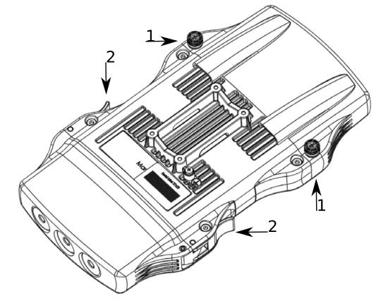
Removing upper and bottom covers
- To remove the upper cover, unscrew two captive screws and slide it off the main body. Do not remove screws completely, when assembling tightening torque 0.2 Nm.
- To remove the bottom cover, release clips for both fasteners and cover will be free to open.
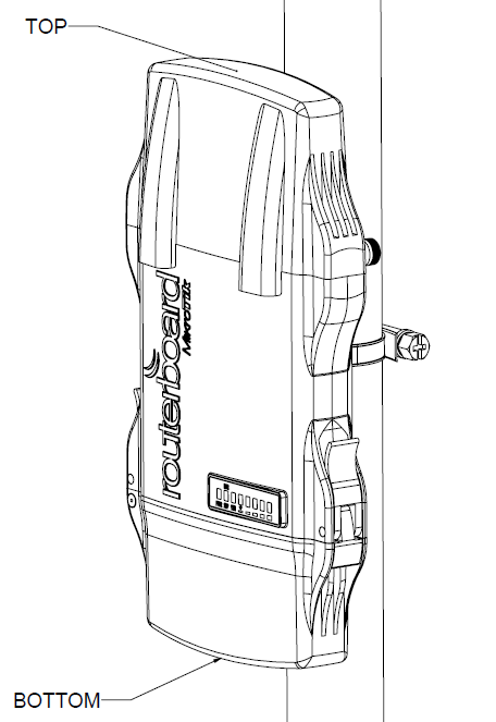
Mounting
The NetMetal ac2 is designed to be used outdoors and mounted on pole or DIN rail. 
When mounting, please ensure that cable feed is pointing downwards.
The IP rating scale of this device is IP55. We recommend using Cat6 shielded cables.
Warning! This equipment should be installed and operated with a minimum distance of 20 cm between the device and your body. Operation of this equipment in the residential environment could cause radio interference.
Mounting and configuration of this device should be done by a qualified person.
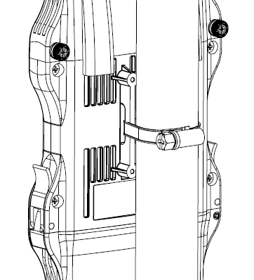
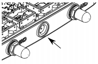
The mounting hose clamp is provided with the package.
- Guide hose clamp through the opening on the back of the device.
- Attach to the pole or mast.
- Align and secure by hose clamp screw using PH2 screwdriver.
- The device should be always placed by TOP cover facing upwards.
- When mounting on DIN rail, please find a special bracket in the package and secure it with four screws to the back of the unit.
- With the attached mounting bracket you will be able to slide the device on the DIN rail.
Grounding
The installation infrastructure (towers and masts), as well as the router itself, must be properly grounded. The device includes a grounding wire attachment screw. Attach your grounding wire to the grounding screw, then attach the other end of the grounding wire to the grounded mast.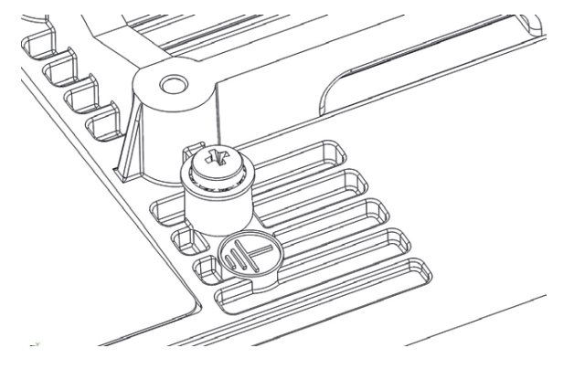
Please secure all loose Ethernet cables and antenna cables to the pole or mast approximately 30cm from the device, so that the cable weight is not pulling the ports and connectors.
Front status LED behavior
RouterOS allows configuring each LED's activity the way that the user wishes. It is possible to configure the LEDs to display wireless strength, blink the LEDs on interface traffic activity and many other options. For further information please visit https://wiki.mikrotik.com/wiki/Manual:System/LEDS
Default factory configuration for this device:
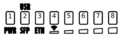
- Solid Blue – The device is powered on.
- Solid Green – Active SFP port.
- Solid Green – Active Ethernet port.
- - 8. Solid Green – The set of five green LEDs, shows the signal strength.
Configuration
The device is configured as a wireless access point, with the Ethernet port configured as a DHCP client, for connecting to your ISP router or switch. A DHCP server is configured on the wireless interface.
We recommend clicking the "Check for updates" button in the QuickSet menu, as updating your RouterOS software to the latest version ensures the best performance and stability. For wireless models, please make sure you have selected the country where the device will be used, to conform with local regulations.
RouterOS includes many configuration options in addition to what is described in this document. We suggest starting here to get yourself accustomed to the possibilities: https://mt.lv/help. In case IP connection is not available, the Winbox tool (https://mt.lv/winbox) can be used to connect to the MAC address of the device from the LAN side (all access is blocked from the Internet port by default).
For recovery purposes, it is possible to boot the device for reinstallation, see a section Reset button.
Expansion slots and ports
- Gigabit Ethernet port, supporting automatic cross/straight cable correction (Auto MDI/X). Either straight or crossover cable can be used for connecting to other network devices.
- SFP port.
- External SMA antenna connectors.
- MiniPCIe slot.
- Integrated Wireless module operating at 2.4 GHz, 802.11b/g/n protocol.
- Integrated Wireless module operating at 5 GHz, 802.11a/n/ac protocol.
- USB type-A.
Reset button
The reset button has three functions:
- Hold this button during boot time until LED light starts flashing, release the button to reset RouterOS configuration (total 5 seconds).
- Keep holding for 5 more seconds, LED turns solid, release now to turn on CAP mode. The device will now look for a CAPsMAN server (total 10 seconds).
- Or Keep holding the button for 5 more seconds until LED turns off, then release it to make the RouterBOARD look for Netinstall servers (total 15 seconds).
Regardless of the above option used, the system will load the backup RouterBOOT loader if the button is pressed before power is applied to the device. Useful for RouterBOOT debugging and recovery.
Accessories
Package includes the following accessories that come with the device:
- EU Switching Power Supply 48 V ⎓ 0.95 A 45.6 W.
- Gigabit POE injector.
- K-27 DIN rail bracket mounting set.
- Hose clamp 40/60 w2 A2 9 mm.
Please visit wiki pages for MikroTik SFP module compatibility table: https://wiki.mikrotik.com/wiki/MikroTik_SFP_module_compatibility_table
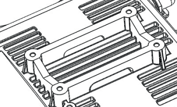
MiniPCIe slot usage
This NetMetal version is without modem installed. To install the module you will need to remove the upper cover and open bottom cover (see "NetMetal ac²#Removing upper and bottom covers"). Installing a miniPCIe module should be done by a qualified person, please follow safety precautions when handling electrical equipment:
- Use a wrist grounding strap when unpacking and working with electrical components to avoid electrical discharge (ESD) damage.
- Removing four screws using the PH2 screwdriver.
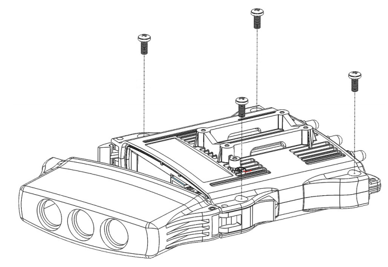
- Remove the top cover by lifting it.
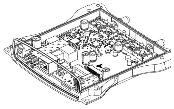
- Locate the miniPCIe slot on the PCB and remove two factory attached screws.
- Attach provided a thick thermal pad to the card, and install the card into miniPCIe slot so that the thermal pad is between PCB and card.
- The secure card in place using previously removed two screws.
- Attach the grey uFL connector to the MAIN antenna connector of the modem, attach the black cable to the secondary (or AUX) connector.
- Attach a thinner thermal pad to the top of the card.
- Drill a hole for cables using a 6.5 mm drill to provide an opening for card antenna cables.
- Guide through the card cables.
- Reassemble.
When assembling make sure the rubber sealing is placed firmly around the case for equal spread to prevent water contamination. Case screw torque 2,5 Nm.
When mounting the antenna for the installed card, please make sure to keep them separate at a good distance from Wireless antennas.
Antenna usage
Antenna Installation. WARNING: It is the installer's responsibility to ensure that when using the authorized antennas in the United States (or where FCC rules apply); only those antennas certified with the product are used. The use of any antenna other than those certified with the product is expressly forbidden in accordance with FCC rules CFR47 part 15.204. The installer should configure the output power level of antennas, according to country regulations and per antenna type. Professional installation is required for equipment with connectors to ensure compliance with health and safety issues.
LIST OF APPROVED 2GHz ANTENNAS:
- 5 dBi Dipole ACOMNIRPSMA
LIST OF APPROVED 5GHz ANTENNAS:
- 30 dBi Parabolic dish MTAD-5G-30D3
- 19 dBi Sector MTAS-5G-19D120
Antennas of the same type and lower gain than those listed above may be used in compliance with certification.
More information on the wireless interface: https://wiki.mikrotik.com/wiki/Manual:Interface/Wireless
Specifications
For more information about this product, specifications, pictures, downloads and test results please visit our web page: https://mikrotik.com/product/NetMetal_ac2
Operating system support
The device supports RouterOS software version 6. The specific factory-installed version number is indicated in the RouterOS menu /system resource. Other operating systems have not been tested.
Safety Warnings
Before you work on any equipment, be aware of the hazards involved with electrical circuitry and be familiar with standard practices for preventing accidents.
Ultimate disposal of this product should be handled according to all national laws and regulations.
The Installation of the equipment must comply with local and national electrical codes.
This unit is intended to be mounted on a pole. Please read the wall mounting instructions carefully before beginning installation. Failure to use the correct hardware or to follow the correct procedures could result in a hazardous situation to people and damage to the system.
Read the installation instructions before connecting the system to the power source.
It is the customer's responsibility to follow local country regulations, including operation within legal frequency channels, output power, cabling requirements, and Dynamic Frequency Selection (DFS) requirements. All Mikrotik radio devices must be professionally installed.