Introduction
There are several types of switch chips on Routerboards and they have different sets of features. Most of them (from now on "Other") have only the basic "Port Switching" feature, but there are a few with more features:
| Feature | QCA8337 | Atheros8327 | Atheros8316 | Atheros8227 | Atheros7240 | IPQ-PPE | ICPlus175D | MT7621, MT7531 | RTL8367 | 88E6393X | 88E6191X, 88E6190 | 98PX1012 | Other |
|---|---|---|---|---|---|---|---|---|---|---|---|---|---|
| Port Switching | yes | yes | yes | yes | yes | yes | yes | yes | yes | yes | yes | no | yes |
| Port Mirroring | yes | yes | yes | yes | yes | no | yes | yes | yes | yes | yes | no | no |
| TX limit 1 | yes | yes | yes | yes | yes | no | no | yes | yes | yes | yes | no | no |
| RX limit 1 | yes | yes | no | no | no | no | no | yes | yes | yes | yes | no | no |
| Host table | 2048 entries | 2048 entries | 2048 entries | 1024 entries | 2048 entries | 2048 entries | 2048 entries 2 | 2048 entries | 2048 entries | 16k entries | 16k entries | no | no |
| Vlan table | 4096 entries | 4096 entries | 4096 entries | 4096 entries | 16 entries | no | no | 4096 entries 3 | 4096 entries 3 | 4096 entries 3 | 4096 entries 3 | no | no |
| Rule table | 92 rules | 92 rules | 32 rules | no | no | no | no | no | no | 256 | no | no | no |
Notes
- For QCA8337, Atheros8327, Atheros8316, Atheros8227, and Atheros7240 the Tx/Rx rate limits can be changed with
bandwidthproperty on"/interface ethernet"menu, see more details in the Ethernet manual. For RTL8367, 88E6393X, 88E6191X, 88E6190, MT7621 and MT7531 Tx/Rx rate limit can be changed withegress-rateandingress-rateproperties on "/interface ethernet switch port" menu. - MAC addresses are learned up to the specified number, but the content of a switch host table is not available in RouterOS and static host configuration is not supported.
- Bridge HW vlan-filtering was added in the RouterOS 7.1rc1 (for RTL8367) and 7.1rc5 (for MT7621) versions. The switch does not support other
ether-type0x88a8 or 0x9100 (only 0x8100 is supported) and notag-stacking. Using these features will disable HW offload.
Cloud Router Switch (CRS) series devices have highly advanced switch chips built-in, they support a wide variety of features. For more details about switch chip capabilities on CRS1xx/CRS2xx series devices check the CRS1xx/CRS2xx series switches manual, for CRS3xx series devices check the CRS3xx, CRS5xx series switches, and CCR2116, CCR2216 routers manual.
| RouterBoard | Switch-chip description |
|---|---|
| C52iG-5HaxD2HaxD-TC (hAP ax2), C53UiG+5HPaxD2HPaxD (hAP ax3), Chateau ax series | IPQ-PPE (ether1-ether5) |
| cAPGi-5HaxD2HaxD (cAP ax) | IPQ-PPE (ether1-ether2) |
| L009 series | 88E6190 (ether2-ether8, sfp1) |
| RB5009 series | 88E6393X (ether1-ether8, sfp-sfpplus1) |
| CCR2004-16G-2S+ | 88E6191X (ether1-ether8); 88E6191X (ether9-ether16); |
| RB4011iGS+ | RTL8367 (ether1-ether5); RTL8367 (ether6-ether10); |
| RB1100AHx4 | RTL8367 (ether1-ether5); RTL8367 (ether6-ether10); RTL8367 (ether11-ether13) |
| L41G-2axD (hAP ax lite) | MT7531 (ether1-ether4) |
| RB750Gr3 (hEX), RB760iGS (hEX S) | MT7621 (ether1-ether5) |
| RBM33G | MT7621 (ether1-ether3) |
| RB3011 series | QCA8337 (ether1-ether5); QCA8337 (ether6-ether10) |
| RB OmniTik ac series | QCA8337 (ether1-ether5) |
| RBwsAP-5Hac2nD (wsAP ac lite) | Atheros8227 (ether1-ether3) |
| RB941-2nD (hAP lite) | Atheros8227 (ether1-ether4) |
| RB951Ui-2nD (hAP); RB952Ui-5ac2nD (hAP ac lite); RB750r2 (hEX lite); RB750UPr2 (hEX PoE lite); RB750P-PBr2 (PowerBox); RB750P r2; RBOmniTikU-5HnDr2 (OmniTIK 5); RBOmniTikUPA-5HnDr2 (OmniTIK 5 PoE) | Atheros8227 (ether1-ether5) |
| RB750Gr2 (hEX); RB962UiGS-5HacT2HnT (hAP ac); RB960PGS (hEX PoE); RB960PGS-PB (PowerBox Pro) | QCA8337 (ether1-ether5) |
| RB953GS | Atheros8327 (ether1-ether3+sfp1) |
| RB850Gx2 | Atheros8327 (ether1-ether5) with ether1 optional |
| RB2011 series | Atheros8327 (ether1-ether5+sfp1); Atheros8227 (ether6-ether10) |
| RB750GL; RB751G-2HnD; RB951G-2HnD; RBD52G-5HacD2HnD (hAP ac²), RBD53iG-5HacD2HnD (hAP ac³), RBD53GR-5HacD2HnD&R11e-LTE6 (hAP ac³ LTE6 kit), RBD53G-5HacD2HnD-TC&EG12-EA (Chateau LTE12) | Atheros8327 (ether1-ether5) |
| RBcAPGi-5acD2nD (cAP ac), RBwAPGR-5HacD2HnD (wAP R ac and wAP ac LTE series), RBwAPG-5HacD2HnD (wAP ac), RBD25G-5HPacQD2HPnD (Audience), RBD25GR-5HPacQD2HPnD&R11e-LTE6 (Audience LTE6 kit), | Atheros8327 (ether1-ether2) |
| RBD22UGS-5HPacD2HnD (mANTBox 52 15s) | Atheros8327 (ether1-sfp1) |
| RB1100AH | Atheros8327 (ether1-ether5); Atheros8327 (ether6-ether10) |
| RB1100AHx2 | Atheros8327 (ether1-ether5); Atheros8327 (ether6-ether10) |
| CCR1009-8G-1S-1S+; CCR1009-8G-1S | Atheros8327 (ether1-ether4) |
| RB493G | Atheros8316 (ether1+ether6-ether9); Atheros8316 (ether2-ether5) |
| RB435G | Atheros8316 (ether1-ether3) with ether1 optional |
| RB450G | Atheros8316 (ether1-ether5) with ether1 optional |
| RB450Gx4 | Atheros8327 (ether1-ether5) |
| RB433GL | Atheros8327 (ether1-ether3) |
| RB750G | Atheros8316 (ether1-ether5) |
| RB1200 | Atheros8316 (ether1-ether5) |
| RB1100 | Atheros8316 (ether1-ether5); Atheros8316 (ether6-ether10) |
| DISC Lite5 | Atheros8227 (ether1) |
| RBmAP2nD | Atheros8227 (ether1-ether2) |
| RBmAP2n | Atheros7240 (ether1-ether2) |
| RB750 | Atheros7240 (ether2-ether5) |
| RB750UP | Atheros7240 (ether2-ether5) |
| RB751U-2HnD | Atheros7240 (ether2-ether5) |
| RB951-2n | Atheros7240 (ether2-ether5) |
| RB951Ui-2HnD | Atheros8227 (ether1-ether5) |
| RB433 series | ICPlus175D (ether2-ether3); older models had ICPlus175C |
| RB450 | ICPlus175D (ether2-ether5); older models had ICPlus175C |
| RB493 series | ICPlus178C (ether2-ether9) |
| RB816 | ICPlus178C (ether1-ether16) |
The command-line configuration is under the switch menu. This menu contains a list of all switch chips present in the system and some sub-menus as well.
[admin@MikroTik] > /interface ethernet switch print
Flags: I - invalid
 #   NAME         TYPE             MIRROR-SOURCE       MIRROR-TARGET       SWITCH-ALL-PORTS
 0   switch1      Atheros-8327     none                none
 1   switch2      Atheros-8227     none                none
Depending on the switch type there can be different configuration capabilities available.
Features
Port Switching
To set up port switching on non-CRS series devices, check the Bridge Hardware Offloading page.
Port switching in RouterOS v6.41 and newer is done using the bridge configuration. Before RouterOS v6.41 port switching was done using the master-port property.
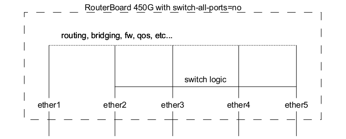
Switch All Ports Feature
Ether1 port on RB450G/RB435G/RB850Gx2 devices has a feature that allows it to be removed/added to the default switch group, this setting is available on the /interface ethernet switch menu. By default ether1 port will be included in the switch group.
| Property | Description |
|---|---|
| switch-all-ports (no | yes; Default: yes) | Changes ether1 switch group only on RB450G/RB435G/RB850Gx2 devices.
|
Port Mirroring
Port mirroring lets the switch to copy all traffic that is going in and out of one port (mirror-source) and send out these copied frames to some other port (mirror-target). This feature can be used to easily set up a 'tap' device that receives all traffic that goes in/out of some specific port. Note that mirror-source and mirror-target ports have to belong to the same switch (see which port belongs to which switch in /interface ethernet menu). Also, mirror-target can have a special 'cpu' value, which means that mirrored packets should be sent out to the switch chips CPU port. Port mirroring happens independently of switching groups that have or have not been set up.
Sub-menu: /interface ethernet switch
| Property | Description |
|---|---|
| mirror-source (name | none; Default: none) | Selects a single mirroring source port. Ingress and egress traffic will be sent to the |
| mirror-target (name | none | cpu; Default: none) | Selects a single mirroring target port. Mirrored packets from |
| mirror-egress-target (name | none; Default: none) | Selects a single mirroring egress target port, only available on 88E6393X, 88E6191X and 88E6190 switch chips. Mirrored packets from |
Sub-menu: /interface ethernet switch rule
| Property | Description |
|---|---|
| mirror (no | yes; Default: no) | Whether to send a packet copy to mirror-target port. |
| mirror-ports (name; Default: ) | Selects multiple mirroring target ports, only available on 88E6393X switch chip. Matched packets in the ACL rule will be copied and sent to selected ports. |
Sub-menu: /interface ethernet switch host
| Property | Description |
|---|---|
| mirror (no | yes; Default: no) | Whether to send a frame copy to mirror-target port from a frame with a matching MAC destination address (matching destination or source address for CRS3xx series switches) |
Sub-menu: /interface ethernet switch port
| Property | Description |
|---|---|
| mirror-egress (no | yes; Default: no) | Whether to send egress packet copy to the |
| mirror-ingress (no | yes; Default: no) | Whether to send ingress packet copy to the |
| mirror-ingress-target (name | none; Default: none) | Selects a single mirroring ingress target port, only available on 88E6393X, 88E6191X and 88E6190 switch chips. Mirrored packets from |
Port mirroring configuration example:
/interface ethernet switch
set switch1 mirror-source=ether2 mirror-target=ether3
If you set mirror-source as an Ethernet port for a device with at least two switch chips and these mirror-source ports are in a single bridge while mirror-target for both switch chips are set to send the packets to the CPU, then this will result in a loop, which can make your device inaccessible.
Port Settings
Properties under this menu are used to configure VLAN switching and filtering options for switch chips that support a VLAN Table. These properties are only available to switch chips that have VLAN Table support, check the Switch Chip Features table to make sure your device supports such a feature.
Ingress traffic is considered as traffic that is being sent IN a certain port, this port is sometimes called ingress port. Egress traffic is considered as traffic that is being sent OUT of a certain port, this port is sometimes called egress port. Distinguishing them is very important to properly set up VLAN filtering since some properties apply only to either ingress or egress traffic.
| Property | Description |
|---|---|
| vlan-mode (check | disabled | fallback | secure; Default: disabled) | Changes the VLAN lookup mechanism against the VLAN Table for ingress traffic.
|
| vlan-header (add-if-missing | always-strip | leave-as-is; Default: leave-as-is) | Sets action which is performed on the port for egress traffic.
|
| default-vlan-id (auto | integer: 0..4095; Default: auto) | Adds a VLAN tag with the specified VLAN ID on all untagged ingress traffic on a port, should be used with vlan-header set to always-strip on a port to configure the port to be the access port. For hybrid ports default-vlan-id is used to tag untagged traffic. If two ports have the same default-vlan-id, then VLAN tag is not added since the switch chip assumes that traffic is being forwarded between access ports. |
On QCA8337 and Atheros8327 switch chips, a default vlan-header=leave-as-is property should be used. The switch chip will determine which ports are access ports by using the default-vlan-id property. The default-vlan-id should only be used on access/hybrid ports to specify which VLAN the untagged ingress traffic is assigned to.
VLAN Table
VLAN table specifies certain forwarding rules for packets that have a specific 802.1Q tag. Those rules are of higher priority than switch groups configured using the Bridge Hardware Offloading feature. Basically, the table contains entries that map specific VLAN tag IDs to a group of one or more ports. Packets with VLAN tags leave the switch chip through one or more ports that are set in the corresponding table entry. The exact logic that controls how packets with VLAN tags are treated is controlled by a vlan-mode parameter that is changeable per switch port.
VLAN ID based forwarding takes into account the MAC addresses dynamically learned or manually added in the host table. QCA8337 and Atheros8327 switch-chips also support Independent VLAN Learning (IVL) which does the learning based on both - MAC addresses and VLAN IDs, thus allowing the same MAC to be used in multiple VLANs.
Packets without VLAN tag are treated just as if they had a VLAN tag with port default-vlan-id. If vlan-mode=check or vlan=mode=secure is configured, to forward packets without VLAN tags you have to add an entry to the VLAN table with the same VLAN ID according to default-vlan-id.
| Property | Description |
|---|---|
| disabled (no | yes; Default: no) | Enables or disables switch VLAN entry. |
| independent-learning (no | yes; Default: yes) | Whether to use shared-VLAN-learning (SVL) or independent-VLAN-learning (IVL). |
| ports (name; Default: none) | Interface member list for the respective VLAN. This setting accepts comma-separated values. e.g. ports=ether1,ether2. |
| switch (name; Default: none) | Name of the switch for which the respective VLAN entry is intended for. |
| vlan-id (integer: 0..4095; Default: ) | The VLAN ID for certain switch port configurations. |
Devices with MT7621, MT7531, RTL8367, 88E6393X, 88E6191X, 88E6190 switch chips support HW offloaded vlan-filtering in RouterOS v7. VLAN-related configuration on the "/interface ethernet switch" menu is not available.
VLAN Forwarding
Both vlan-mode and vlan-header along with the VLAN Table can be used to configure VLAN tagging, untagging and filtering, multiple combinations are possible, each achieving a different result. Below you can find a table of what kind of traffic is going to be sent out through an egress port when a certain traffic is received on an ingress port for each VLAN Mode.
NOTES:
- L -
vlan-headeris set toleave-as-is - S -
vlan-headerset toalways-strip - A -
vlan-headerset toadd-if-missing - U - Untagged traffic is sent out
- T - Tagged traffic is sent out, a tag is already present on the ingress port
- TA - Tagged traffic is sent out, a tag was added on the ingress port
- DI - Traffic is dropped on ingress port because of mode selected in vlan-mode
- DE - Traffic is dropped on egress port because egress port was not found in the VLAN Table
- VID match - VLAN ID from the VLAN tag for ingress traffic is present in the VLAN Table
- Port match - Ingress port is present in the VLAN Table for the appropriate VLAN ID
| VLAN Mode = disabled | Egress port not present in VLAN Table | Egress port is present in VLAN Table | ||||
|---|---|---|---|---|---|---|
| L | S | A | L | S | A | |
| Untagged traffic | U | U | TA | U | U | TA |
| Tagged traffic; no VID match | T | U | T | |||
| Tagged traffic; VID match; no Port match | T | U | T | T | U | T |
| Tagged traffic; VID match; Port match | T | U | T | T | U | T |
| VLAN Mode = fallback | Egress port not present in VLAN Table | Egress port is present in VLAN Table | ||||
|---|---|---|---|---|---|---|
| L | S | A | L | S | A | |
| Untagged traffic | U | U | TA | U | U | TA |
| Tagged traffic; no VID match | T | U | T | |||
| Tagged traffic; VID match; no Port match | DE | DE | DE | T | U | T |
| Tagged traffic; VID match; Port match | DE | DE | DE | T | U | T |
| VLAN Mode = check | Egress port not present in VLAN Table | Egress port is present in VLAN Table | ||||
|---|---|---|---|---|---|---|
| L | S | A | L | S | A | |
| Untagged traffic | ||||||
| Tagged traffic; no VID match | DI | DI | DI | |||
| Tagged traffic; VID match; no Port match | DE | DE | DE | T | U | T |
| Tagged traffic; VID match; Port match | DE | DE | DE | T | U | T |
| VLAN Mode = secure | Egress port not present in VLAN Table | Egress port is present in VLAN Table | ||||
|---|---|---|---|---|---|---|
| L | S | A | L | S | A | |
| Untagged traffic | ||||||
| Tagged traffic; no VID match | DI | DI | DI | |||
| Tagged traffic; VID match; no Port match | DI | DI | DI | DI | DI | DI |
| Tagged traffic; VID match; Port match | DE | DE | DE | T | U | T |
The tables above are meant for more advanced configurations and to double-check your understanding of how packets will be processed with each VLAN related property.
Host Table
The host table represents switch chip's internal MAC address to port mapping. It can contain two kinds of entries: dynamic and static. Dynamic entries get added automatically, this is also called a learning process: when switch chip receives a packet from a certain port, it adds the packet's source MAC address and port it received the packet from to the host table, so when a packet comes in with the same destination MAC address, it knows to which port it should forward the packet. If the destination MAC address is not present in the host table (so-called unknown-unicast traffic) then it forwards the packet to all ports in the group. Dynamic entries take about 5 minutes to time out. Learning is enabled only on ports that are configured as part of the switch group, so you won't see dynamic entries if you have not set up port switching. Also, you can add static entries that take over dynamic if a dynamic entry with the same MAC address already exists. Since port switching is configured using a bridge with hardware offloading, any static entries created on one table (either bridge host or switch host) will appear on the opposite table as a dynamic entry. Adding a static entry on the switch host table will provide access to some more functionality that is controlled via the following params:
| Property | Description |
|---|---|
| copy-to-cpu (no | yes; Default: no) | Whether to send a frame copy to switch CPU port from a frame with a matching MAC destination address (matching destination or source address for CRS3xx series switches) |
| drop (no | yes; Default: no) | Whether to drop a frame with a matching MAC source address received on a certain port (matching destination or source address for CRS3xx series switches) |
| mac-address (MAC; Default: 00:00:00:00:00:00) | Host's MAC address |
| mirror (no | yes; Default: no) | Whether to send a frame copy to mirror-target port from a frame with a matching MAC destination address (matching destination or source address for CRS3xx series switches) |
| ports (name; Default: none) | Name of the interface, static MAC address can be mapped to more than one port, including switch CPU port |
| redirect-to-cpu (no | yes; Default: no) | Whether to redirect a frame to switch CPU port from a frame with a matching MAC destination address (matching destination or source address for CRS3xx series switches) |
| share-vlan-learned (no | yes; Default: no) | Whether the static host MAC address lookup is used with shared-VLAN-learning (SVL) or independent-VLAN-learning (IVL). The SVL mode is used for those VLAN entries that do not support IVL or IVL is disabled (independent-learning=no) |
| switch (name; Default: none) | Name of the switch to which the MAC address is going to be assigned to |
| vlan-id (integer: 0..4095; Default: ) | VLAN ID for the statically added MAC address entry |
Every switch chip has a finite number of MAC addresses it can store on the chip, see the Introduction table for a specific host table size. Once a host table is full, different techniques can be utilized to cope with the situation, for example, the switch can remove older entries to free space for more recent MAC addresses (used on QCA-8337 and Atheros-8327 switch chips), another option is to simply ignore the new MAC addresses and only remove entries after a timeout has passed (used on Atheros8316, Atheros8227, Atheros-7240, ICPlus175D and Realtek-RTL8367 switch chips), the last option is a combination of the previous two - only allow a certain amount of entries to be renewed and keep the other host portion intact till the timeout (used on MediaTek-MT7621, MT7531 switch chip). These techniques cannot be changed with configuration.
For Atheros8316, Atheros8227 and Atheros-7240 switch chips, the switch-cpu port will always participate in the host learning process when at least one hardware offloaded bridge port is active on the switching group. It will cause the switch-cpu port to learn MAC addresses from non-HW offloaded interfaces. This might cause packet loss when a single bridge contains HW and non-HW offloaded interfaces. Also, packet loss might appear when a duplicate MAC address is used on the same switching group regardless if hosts are located on different logical networks. It is recommended to use HW offloading only when all bridge ports can use HW offloaded or keep it disabled on all switch ports when one or more bridge ports cannot be configured with HW offloading.
Rule Table
Rule table is a very powerful tool allowing wire-speed packet filtering, forwarding and VLAN tagging based on L2, L3 and L4 protocol header field conditions. The menu contains an ordered list of rules just like in /ip firewall filter, so ACL rules are checked for each packet until a match has been found. If multiple rules can match, then only the first rule will be triggered. A rule without any action parameters is a rule to accept the packet.
Each rule contains a conditions part and an action part. The action part is controlled by the following parameters:
| Property | Description |
|---|---|
| copy-to-cpu (no | yes; Default: no) | Whether to send a packet copy to switch CPU port |
| mirror (no | yes; Default: no) | Whether to send a packet copy to mirror-target port |
| new-dst-ports (name; Default: none) | Changes the destination port as specified, multiple ports allowed, including a switch CPU port. An empty setting will drop the packet. When the parameter is not used, the packet will be accepted |
| new-vlan-id (integer: 0..4095) | Changes the VLAN ID to the specified value or adds a new VLAN tag if one was not already present (the property only applies to the Atheros8316, and 88E6393X switch chips) |
| new-vlan-priority (integer: 0..7) | Changes the VLAN priority field (priority code point, the property only applies to Atheros8327, QCA8337 and Atheros8316 switch chips) |
| rate (integer: 0..4294967295) | Sets ingress traffic limitation (bits per second) for matched traffic, can only be applied to the first 32 rule slots (the property only applies to Atheros8327/QCA8337 switch chips) |
| redirect-to-cpu (no | yes; Default: no) | Changes the destination port of a matching packet to the switch CPU |
The conditions part is controlled by the rest of the parameters:
| Property | Description |
|---|---|
| disabled (no | yes; Default: no) | Enables or disables switch rule |
| dscp (integer: 0..63) | Matching DSCP field of the packet |
| dst-address (IP address/Mask) | Matching destination IP address and mask |
| dst-address6 (IPv6 address/Mask) | Matching destination IPv6 address and mask |
| dst-mac-address (MAC address/Mask) | Matching destination MAC address and mask |
| dst-port (integer: 0..65535) | Matching destination protocol port number or range |
| flow-label (integer: 0..1048575) | Matching IPv6 flow label |
| mac-protocol (802.2 | arp | homeplug-av | ip | ipv6 | ipx | lldp | loop-protect | mpls-multicast | mpls-unicast | packing-compr | packing-simple | pppoe | pppoe-discovery | rarp | service-vlan | vlan | or 0..65535 | or 0x0000-0xffff) | Matching particular MAC protocol specified by protocol name or number (skips VLAN tags if any) |
| ports (name) | Name of the interface on which the rule will apply on the received traffic, multiple ports are allowed |
| protocol (dccp | ddp | egp | encap | etherip | ggp | gre | hmp | icmp | icmpv6 | idpr-cmtp | igmp | ipencap | ipip | ipsec-ah | ipsec-esp | ipv6 | ipv6-frag | ipv6-nonxt | ipv6-opts | ipv6-route | iso-tp4 | l2tp | ospf | pim | pup | rdp | rspf | rsvp | sctp | st | tcp | udp | udp-lite | vmtp | vrrp | xns-idp | xtp | or 0..255) | Matching particular IP protocol specified by protocol name or number |
| src-address (IP address/Mask) | Matching source IP address and mask |
| src-address6 (IPv6 address/Mask) | Matching source IPv6 address and mask |
| src-mac-address (MAC address/Mask) | Matching source MAC address and mask |
| src-port (0..65535) | Matching source protocol port number or range |
| switch (switch group) | Matching switch group on which will the rule apply |
| traffic-class (0..255) | Matching IPv6 traffic class |
| vlan-id (0..4095) | Matching VLAN ID (the property only applies to the Atheros8316, Atheros8327, QCA8337, 88E6393X switch chips) |
| vlan-header (not-present | present) | Matching VLAN header, whether the VLAN header is present or not (the property only applies to the Atheros8316, Atheros8327, QCA8337, 88E6393X switch chips) |
| vlan-priority (0..7) | Matching VLAN priority (priority code point) |
IPv4 and IPv6 specific conditions cannot be present in the same rule.
Because the rule table is processed entirely in switch chips hardware, there is a limitation to how many rules you may have. Depending on the number of conditions (MAC layer, IP layer, IPv6, L4 layer) you use in your rules, the number of active rules may vary from 8 to 32 for Atheros8316 switch chip, from 24 to 96 for Atheros8327/QCA8337 switch chip and from 42 to 256 for 88E6393X switch chip. You can always do /interface ethernet switch rule print after modifying your rule set to see that no rules at the end of the list are 'invalid' which means those rules did not fit into the switch chip.
Port isolation
Port isolation provides the possibility to divide (isolate) certain parts of your network, this might be useful when you need to make sure that certain devices cannot access other devices, this can be done by isolating switch ports. Port isolation only works between ports that are members of the same switch. Switch port isolation is available on all switch chips since RouterOS v6.43.
| Property | Description |
|---|---|
| forwarding-override (interface; Default: ) | Forces ingress traffic to be forwarded to a specific interface. Multiple interfaces can be specified by separating them with a comma. |
(R/M)STP will only work properly in PVLAN setups, (R/M)STP will not work properly in setups, where there are multiple isolated switch groups, because switch groups might not properly receive BPDUs and therefore fail to detect network loops.
The forwarding-override property affects ingress traffic only. Switch ports that do not have the forwarding-override specified can send packets through all switch ports.
Switch chips with a VLAN table support (QCA8337, Atheros8327, Atheros8316, Atheros8227 and Atheros7240) can override the port isolation configuration when enabling a VLAN lookup on the switch port (the vlan-mode is set to fallback, check or secure). If additional port isolation is needed between ports on the same VLAN, a switch rule with a new-dst-ports property can be implemented. Other devices without switch rule support cannot overcome this limitation.
Private VLAN
In some scenarios, you might need to forward all traffic to an uplink port while all other ports are isolated from each other. This kind of setup is called Private VLAN configuration, the Switch will forward all Ethernet frames directly to the uplink port allowing the Router to filter unwanted packets and limit access between devices that are behind switch ports.
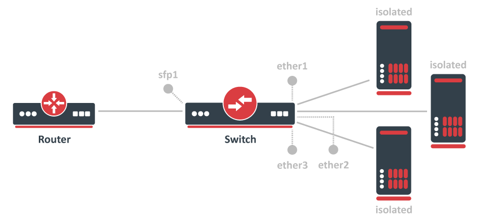
To configure switch port isolation, you need to switch all required ports:
/interface bridge
add name=bridge1
/interface bridge port
add interface=sfp1 bridge=bridge1 hw=yes
add interface=ether1 bridge=bridge1 hw=yes
add interface=ether2 bridge=bridge1 hw=yes
add interface=ether3 bridge=bridge1 hw=yes
By default, the bridge interface is configured with protocol-mode set to rstp. For some devices, this can disable hardware offloading because specific switch chips do not support this feature. See the Bridge Hardware Offloading section with supported features.
Override the egress port for each switch port that needs to be isolated (excluding the uplink port):
/interface ethernet switch port-isolation
set ether1 forwarding-override=sfp1
set ether2 forwarding-override=sfp1
set ether3 forwarding-override=sfp1
It is possible to set multiple uplink ports for a single switch chip, this can be done by specifying multiple interfaces and separating them with a comma.
Isolated switch groups
In some scenarios you might need to isolate a group of devices from other groups, this can be done using the switch port isolation feature. This is useful when you have multiple networks but you want to use a single switch, with port isolation you can allow certain switch ports to be able to communicate through only a set of switch ports. In this example, devices on ether1-3 will only be able to communicate with devices that are on ether1-3, while devices on ether4-5 will only be able to communicate with devices on ether4-5 (ether1-3 is not able to communicate with ether4-5)
Port isolation is only available between ports that are members of the same switch.
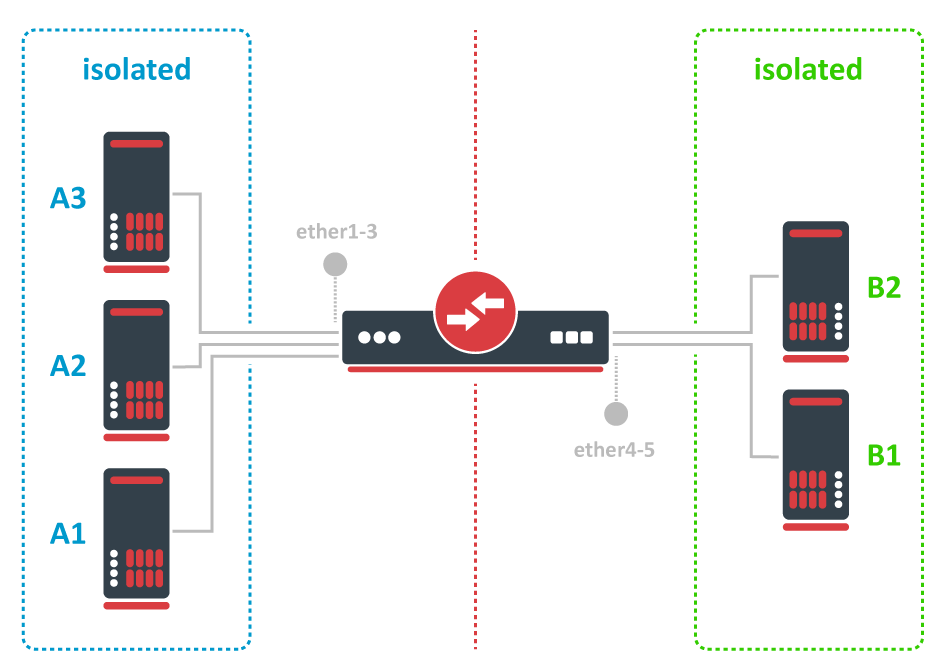
To configure isolated switch groups you must first switch all ports:
/interface bridge
add name=bridge
/interface bridge port
add bridge=bridge1 interface=ether1 hw=yes
add bridge=bridge1 interface=ether2 hw=yes
add bridge=bridge1 interface=ether3 hw=yes
add bridge=bridge1 interface=ether4 hw=yes
add bridge=bridge1 interface=ether5 hw=yes
By default, the bridge interface is configured with protocol-mode set to rstp. For some devices, this can disable hardware offloading because specific switch chips do not support this feature. See the Bridge Hardware Offloading section with supported features.
Then specify in the forwarding-override property all ports that you want to be in the same isolated switch group (except the port on which you are applying the property), for example, to create an isolated switch group for A devices:
/interface ethernet switch port-isolation
set ether1 forwarding-override=ether2,ether3
set ether2 forwarding-override=ether1,ether3
set ether3 forwarding-override=ether1,ether2
To create an isolated switch group for B devices:
/interface ethernet switch port-isolation
set ether4 forwarding-override=ether5
set ether5 forwarding-override=ether4
CPU Flow Control
All switch chips have a special port that is called switchX-cpu, this is the CPU port for a switch chip, it is meant to forward traffic from a switch chip to the CPU, such a port is required for management traffic and routing features. By default the switch chip ensures that this special CPU port is not congested and sends out Pause Frames when link capacity is exceeded to make sure the port is not oversaturated, this feature is called CPU Flow Control. Without this feature packets that might be crucial for routing or management purposes might get dropped.
Since RouterOS v6.43 it is possible to disable the CPU Flow Control feature on some devices that are using one of the following switch chips: Atheros8227, QCA8337, Atheros8327, Atheros7240 or Atheros8316. Other switch chips have this feature enabled by default and cannot be changed. To disable CPU Flow Control use the following command:
/interface ethernet switch set switch1 cpu-flow-control=no
Statistics
Some switch chips are capable of reporting statistics, this can be useful to monitor how many packets are sent to the CPU from the built-in switch chip. These statistics can also be used to monitor CPU Flow Control. You can find an example of the switch chip's statistics below:
[admin@MikroTik] > /interface ethernet switch print stats

                      name:      switch1
            driver-rx-byte:  221 369 701
          driver-rx-packet:    1 802 975
            driver-tx-byte:   42 621 969
          driver-tx-packet:      310 485
                  rx-bytes:  414 588 529
                 rx-packet:    2 851 236
              rx-too-short:            0
               rx-too-long:            0
              rx-broadcast:    1 040 309
                  rx-pause:            0
              rx-multicast:      486 321
              rx-fcs-error:            0
            rx-align-error:            0
               rx-fragment:            0
                rx-control:            0
             rx-unknown-op:            0
           rx-length-error:            0
             rx-code-error:            0
          rx-carrier-error:            0
                 rx-jabber:            0
                   rx-drop:            0
                  tx-bytes:   44 071 621
                 tx-packet:      312 597
              tx-too-short:            0
               tx-too-long:        8 397
              tx-broadcast:        2 518
                  tx-pause:        2 112
              tx-multicast:        7 142
    tx-excessive-collision:            0
     tx-multiple-collision:            0
       tx-single-collision:            0
     tx-excessive-deferred:            0
               tx-deferred:            0
         tx-late-collision:            0
        tx-total-collision:            0
                   tx-drop:            0
                 tx-jabber:            0
              tx-fcs-error:            0
                tx-control:        2 112
               tx-fragment:            0
                  tx-rx-64:        6 646
              tx-rx-65-127:    1 509 891
             tx-rx-128-255:    1 458 299
             tx-rx-256-511:      178 975
            tx-rx-512-1023:          953
           tx-rx-1024-1518:          672
            tx-rx-1519-max:            0
Some devices have multiple CPU cores that are directly connected to a built-in switch chip using separate data lanes. These devices can report which data lane was used to forward the packet from or to the CPU port from the switch chip. For such devices an extra line is added for each row, the first line represents data that was sent using the first data lane, the second line represents data that was sent using the second data line, and so on. You can find an example of the switch chip's statistics for a device with multiple data lanes connecting the CPU and the built-in switch chip:
[admin@MikroTik] > /interface ethernet switch print stats
                  name:      switch1
        driver-rx-byte:  226 411 248
                                   0
      driver-rx-packet:    1 854 971
                                   0
        driver-tx-byte:   45 988 067
                                   0
      driver-tx-packet:      345 282
                                   0
              rx-bytes:  233 636 763
                                   0
             rx-packet:    1 855 018
                                   0
          rx-too-short:            0
                                   0
           rx-too-long:            0
                                   0
              rx-pause:            0
                                   0
          rx-fcs-error:            0
                                   0
           rx-overflow:            0
                                   0
              tx-bytes:   47 433 203
                                   0
             tx-packet:      345 282
                                   0
    tx-total-collision:            0
                                   0
Setup Examples
Make sure you have added all needed interfaces to the VLAN table when using secure vlan-mode. For routing functions to work properly on the same device through ports that use secure vlan-mode, you will need to allow access to the CPU from those ports, this can be done by adding the switchX-cpu interface itself to the VLAN table. Examples can be found in the Management port section.
It is possible to use the built-in switch chip and the CPU at the same time to create a Switch-Router setup, where a device acts as a switch and as a router at the same time. You can find a configuration example in the Switch-Router guide.
When allowing access to the CPU, you are allowing access from a certain port to the actual router/switch, this is not always desirable. Make sure you implement proper firewall filter rules to secure your device when access to the CPU is allowed from a certain VLAN ID and port, use firewall filter rules to allow access to only certain services.
Devices with MT7621, MT7531, RTL8367, 88E6393X, 88E6191X, 88E6190 switch chips support HW offloaded vlan-filtering in RouterOS v7. VLAN-related configuration on the "/interface ethernet switch" menu is not available.
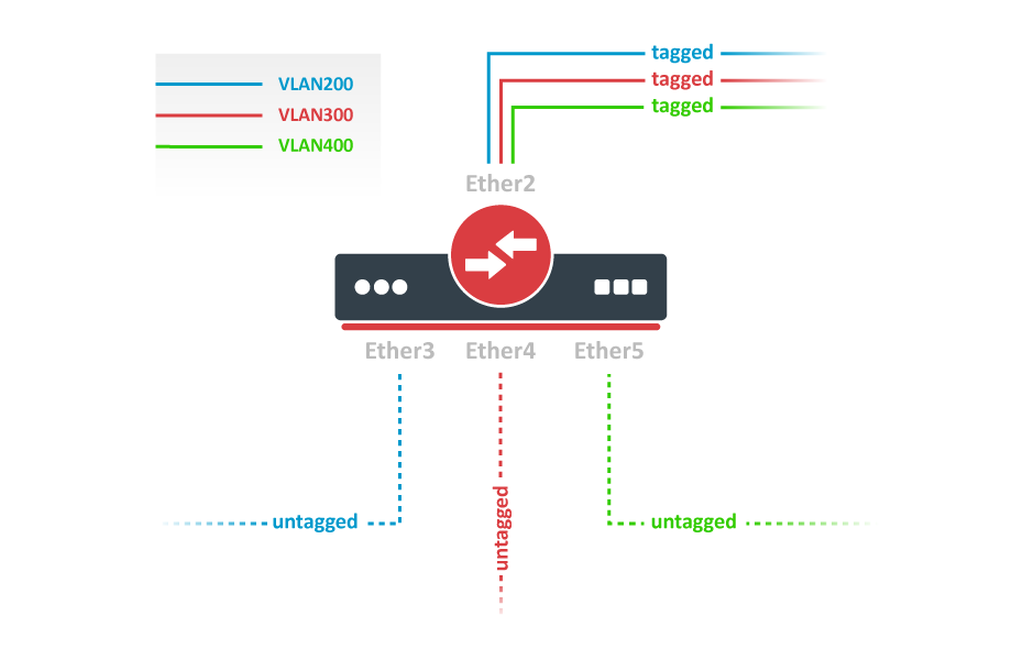
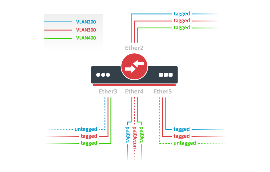
VLAN Example 1 (Trunk and Access Ports)
RouterBOARDs with Atheros switch chips can be used for 802.1Q Trunking. This feature in RouterOS v6 is supported by QCA8337, Atheros8316, Atheros8327, Atheros8227 and Atheros7240 switch chips. In this example, ether3, ether4, and ether5 interfaces are access ports, while ether2 is a trunk port. VLAN IDs for each access port: ether3 - 400, ether4 - 300, ether5 - 200.
Switch together the required ports:
/interface bridge
add name=bridge1
/interface bridge port
add bridge=bridge1 interface=ether2 hw=yes
add bridge=bridge1 interface=ether3 hw=yes
add bridge=bridge1 interface=ether4 hw=yes
add bridge=bridge1 interface=ether5 hw=yes
By default, the bridge interface is configured with protocol-mode set to rstp. For some devices, this can disable hardware offloading because specific switch chips do not support this feature. See the Bridge Hardware Offloading section with supported features.
Add VLAN table entries to allow frames with specific VLAN IDs between ports:
/interface ethernet switch vlan
add ports=ether2,ether3 switch=switch1 vlan-id=200
add ports=ether2,ether4 switch=switch1 vlan-id=300
add ports=ether2,ether5 switch=switch1 vlan-id=400
Assign vlan-mode and vlan-header mode for each port and also default-vlan-id on ingress for each access port:
/interface ethernet switch port
set ether2 vlan-mode=secure vlan-header=add-if-missing
set ether3 vlan-mode=secure vlan-header=always-strip default-vlan-id=200
set ether4 vlan-mode=secure vlan-header=always-strip default-vlan-id=300
set ether5 vlan-mode=secure vlan-header=always-strip default-vlan-id=400
- Setting
vlan-mode=secureensures strict use of the VLAN table. - Setting
vlan-header=always-stripfor access ports removes the VLAN header from the frame when it leaves the switch chip. - Setting
vlan-header=add-if-missingfor trunk port adds VLAN header to untagged frames. default-vlan-idspecifies what VLAN ID is added for untagged ingress traffic of the access port.
On QCA8337 and Atheros8327 switch chips, a default vlan-header=leave-as-is property should be used. The switch chip will determine which ports are access ports by using the default-vlan-id property. The default-vlan-id should only be used on access/hybrid ports to specify which VLAN the untagged ingress traffic is assigned to.
VLAN Example 2 (Trunk and Hybrid Ports)
VLAN Hybrid ports can forward both tagged and untagged traffic. This configuration is supported only by some Gigabit switch chips (QCA8337, Atheros8327).
Switch together the required ports:
/interface bridge
add name=bridge1
/interface bridge port
add bridge=bridge1 interface=ether2 hw=yes
add bridge=bridge1 interface=ether3 hw=yes
add bridge=bridge1 interface=ether4 hw=yes
add bridge=bridge1 interface=ether5 hw=yes
By default, the bridge interface is configured with protocol-mode set to rstp. For some devices, this can disable hardware offloading because specific switch chips do not support this feature. See the Bridge Hardware Offloading section with supported features.
Add VLAN table entries to allow frames with specific VLAN IDs between ports.
/interface ethernet switch vlan
add ports=ether2,ether3,ether4,ether5 switch=switch1 vlan-id=200
add ports=ether2,ether3,ether4,ether5 switch=switch1 vlan-id=300
add ports=ether2,ether3,ether4,ether5 switch=switch1 vlan-id=400
In the switch port menu set vlan-mode on all ports and also default-vlan-id on planned hybrid ports:
/interface ethernet switch port
set ether2 vlan-mode=secure vlan-header=leave-as-is
set ether3 vlan-mode=secure vlan-header=leave-as-is default-vlan-id=200
set ether4 vlan-mode=secure vlan-header=leave-as-is default-vlan-id=300
set ether5 vlan-mode=secure vlan-header=leave-as-is default-vlan-id=400
vlan-mode=securewill ensure strict use of the VLAN table.default-vlan-idwill define VLAN for untagged ingress traffic on the port.- In QCA8337 and Atheros8327 chips when
vlan-mode=secureis used, it ignores switch portvlan-headeroptions. VLAN table entries handle all the egress tagging/untagging and works asvlan-header=leave-as-ison all ports. It means what comes in tagged, goes out tagged as well, onlydefault-vlan-idframes are untagged at the egress port.
Management access configuration
In these examples, there will be shown examples for multiple scenarios, but each of these scenarios requires you to have switched ports. Below you can find how to switch multiple ports:
/interface bridge
add name=bridge1
/interface bridge port
add interface=ether1 bridge=bridge1 hw=yes
add interface=ether2 bridge=bridge1 hw=yes
By default, the bridge interface is configured with protocol-mode set to rstp. For some devices, this can disable hardware offloading because specific switch chips do not support this feature. See the Bridge Hardware Offloading section with supported features.
In these examples, it will be assumed that ether1 is the trunk port and ether2 is the access port, for configuration as the following:
/interface ethernet switch port
set ether1 vlan-header=add-if-missing
set ether2 default-vlan-id=100 vlan-header=always-strip
/interface ethernet switch vlan
add ports=ether1,ether2,switch1-cpu switch=switch1 vlan-id=100
Tagged
To make the device accessible only from a certain VLAN, you need to create a new VLAN interface on the bridge interface and assign an IP address to it:
/interface vlan
add name=MGMT vlan-id=99 interface=bridge1
/ip address
add address=192.168.99.1/24 interface=MGMT
Specify from which interfaces it is allowed to access the device:
/interface ethernet switch vlan
add ports=ether1,switch1-cpu switch=switch1 vlan-id=99
Only specify trunk ports in this VLAN table entry, it is not possible to allow access to the CPU with tagged traffic through an access port since the access port will tag all ingress traffic with the specified default-vlan-id value.
When the VLAN table is configured, you can enable vlan-mode=secure to limit access to the CPU:
/interface ethernet switch port
set ether1 vlan-header=add-if-missing vlan-mode=secure
set ether2 default-vlan-id=100 vlan-header=always-strip vlan-mode=secure
set switch1-cpu vlan-header=leave-as-is vlan-mode=secure
Untagged
To make the device accessible from the access port, create a VLAN interface with the same VLAN ID as set in default-vlan-id, for example, VLAN 100, and add an IP address to it:
/interface vlan
add name=VLAN100 vlan-id=100 interface=bridge1
/ip address
add address=192.168.100.1/24 interface=VLAN100
Specify which access (untagged) ports are allowed to access the CPU:
/interface ethernet switch vlan
add ports=ether1,ether2,switch1-cpu switch=switch1 vlan-id=100
Most commonly an access (untagged) port is accompanied by a trunk (tagged) port. In case of untagged access to the CPU, you are forced to specify both the access port and the trunk port, this gives access to the CPU from the trunk port as well. Not always this is desired and a Firewall might be required on top of VLAN filtering.
When the VLAN table is configured, you can enable vlan-mode=secure to limit access to the CPU:
/interface ethernet switch port
set ether1 vlan-header=add-if-missing vlan-mode=secure
set ether2 default-vlan-id=100 vlan-header=always-strip vlan-mode=secure
set switch1-cpu vlan-header=leave-as-is vlan-mode=secure
To setup the management port using untagged traffic on a device with the Atheros7240 switch chip, you will need to set vlan-header=add-if-missing for the CPU port.
Untagged from tagged port
It is possible to allow access to the device from the trunk (tagged) port with untagged traffic. To do so, assign an IP address on the bridge interface:
/ip address
add address=10.0.0.1/24 interface=bridge1
Specify which ports are allowed to access the CPU. Use vlan-id that is used in default-vlan-id for switch-cpu and trunk ports, by default it is set to 0 or 1.
/interface ethernet switch vlan
add ports=ether1,switch1-cpu switch=switch1 vlan-id=1
When the VLAN table is configured, you can enable vlan-mode=secure to limit access to the CPU:
/interface ethernet switch port
set ether1 default-vlan-id=1 vlan-header=add-if-missing vlan-mode=secure
set switch1-cpu default-vlan-id=1 vlan-header=leave-as-is vlan-mode=secure
This configuration example is not possible for devices with the Atheros8316 and Atheros7240 switch chips. For devices with QCA8337 and Atheros8327 switch chips, it is possible to use any other default-vlan-id as long as it stays the same on switch-cpu and trunk ports. For devices with Atheros8227 switch chip only default-vlan-id=0 can be used and the trunk port must use vlan-header=leave-as-is.
Inter-VLAN routing
Many MikroTik's devices come with a built-in switch chip that can be used to greatly improve overall throughput when configured properly. Devices with a switch chip can be used as a router and a switch at the same time, this gives you the possibility to use a single device instead of multiple devices for your network.
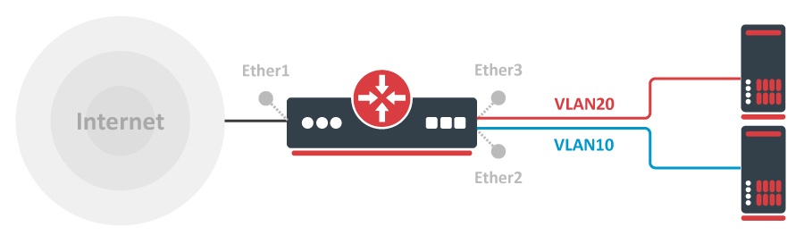
For this type of setup to work, you must switch all required ports together
/interface bridge
add name=bridge1
/interface bridge port
add bridge=bridge1 interface=ether2 hw=yes
add bridge=bridge1 interface=ether3 hw=yes
Create a VLAN interface for each VLAN ID and assign an IP address to it:
/interface vlan
add interface=bridge1 name=VLAN10 vlan-id=10
add interface=bridge1 name=VLAN20 vlan-id=20
/ip address
add address=192.168.10.1/24 interface=VLAN10
add address=192.168.20.1/24 interface=VLAN20
Setup a DHCP Server for each VLAN:
/ip pool
add name=POOL10 ranges=192.168.10.100-192.168.10.200
add name=POOL20 ranges=192.168.20.100-192.168.20.200
/ip dhcp-server
add address-pool=POOL10 disabled=no interface=VLAN10 name=DHCP10
add address-pool=POOL20 disabled=no interface=VLAN20 name=DHCP20
/ip dhcp-server network
add address=192.168.10.0/24 dns-server=8.8.8.8 gateway=192.168.10.1
add address=192.168.20.0/24 dns-server=8.8.8.8 gateway=192.168.20.1
Enable NAT on the device:
/ip firewall nat
add action=masquerade chain=srcnat out-interface=ether1
Add each port to the VLAN table and allow these ports to access the CPU to make DHCP and routing work:
/interface ethernet switch vlan
add independent-learning=yes ports=ether2,switch1-cpu switch=switch1 vlan-id=10
add independent-learning=yes ports=ether3,switch1-cpu switch=switch1 vlan-id=20
Specify each port to be an access port, and enable secure VLAN mode on each port and on the switch1-cpu port:
/interface ethernet switch port
set ether2 default-vlan-id=10 vlan-header=always-strip vlan-mode=secure
set ether3 default-vlan-id=20 vlan-header=always-strip vlan-mode=secure
set switch1-cpu vlan-mode=secure
On QCA8337 and Atheros8327 switch chips, a default vlan-header=leave-as-is property should be used. The switch chip will determine which ports are access ports by using the default-vlan-id property. The default-vlan-id should only be used on access/hybrid ports to specify which VLAN the untagged ingress traffic is assigned to.
If your device has a switch rule table, then you can limit access between VLANs on a hardware level. As soon as you add an IP address on the VLAN interface you enable inter-VLAN routing, but this can be limited on a hardware level while preserving DHCP Server and other router-related services. To do so, use these ACL rules. With this type of configuration, you can achieve isolated port groups using VLANs.
/interface ethernet switch rule
add dst-address=192.168.20.0/24 new-dst-ports="" ports=ether2 switch=switch1
add dst-address=192.168.10.0/24 new-dst-ports="" ports=ether3 switch=switch1