RB911G-5HPacD-NB
Quickstart
Please follow these quick steps to set up your device:
- Remove the upper cover (see "Removing upper cover").
- Connect an external antenna to the SMA connector (see "Antenna usage").
- Open the bottom cover (see "Opening bottom cover").
- Connect the device to the power source (see "Powering").
- Open network connections on your PC, mobile phone or other device and search for MikroTik wireless network and connect to it.
- Recommended using WinBox configuration tool https://mt.lv/winbox.
- Default IP for the device is 192.168.88.1, user name: admin and there is no password.
- Depending on the antenna used, you must set its gain in the RouterOS software to ensure that EIRP meets the limit set by the local authorities. This is done in the Wireless menu.
- We recommend clicking the "Check for updates" button and updating your RouterOS software to the latest version to ensure the best performance and stability.
- Choose your country, to apply country regulation settings and set up your password in the screen that loads.
Powering
The device accepts power in the following ways:
- Ethernet port accepts Passive PoE 8-30 V DC ⎓.
The power consumption under maximum load can reach 11.5 W.
Connecting to a PoE Adapter:
- Connect the Ethernet cable from the device to the PoE+DATA port of the PoE adapter.
- Connect an Ethernet cable from your local network (LAN) to the PoE adapter.
- Connect the power cord to the adapter, and then plug the power cord into a power outlet.
MikroTik mobile app
Use the MikroTik smartphone app to configure your router in the field, or to apply the most basic initial settings for your MikroTik home access point.

- Scan QR code and choose your preferred OS.
- Install and open application.
- By default, IP address and user name will be already entered.
- Click Connect to establish a connection to your device through a wireless network.
- Choose Quick setup and application will guide you through all basic configuration settings in a couple of easy steps.
- Advanced menu is available to fully configure all necessary settings.
Removing upper cover
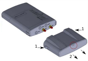
- To remove upper cover, press both side clips.
- Pull cover to the side while holding the body. When assembling please not mark on the top cover or reference.
Opening bottom cover
- To open the bottom cover, press clip upwards to release.
- Pull cover slightly from the device body.
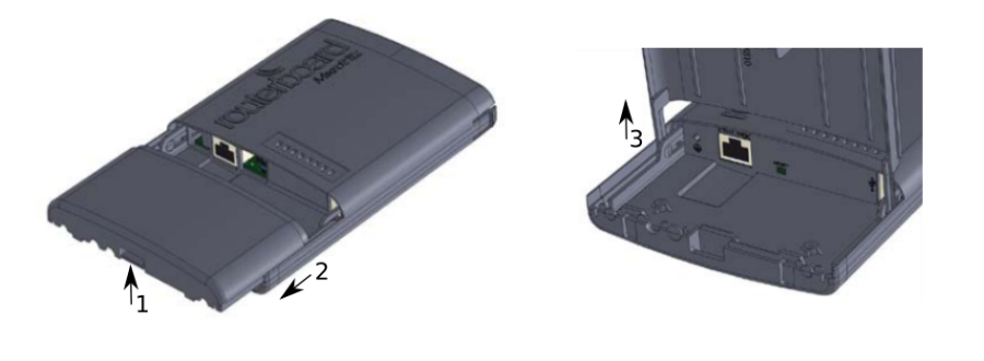
- Lift it, but do not remove completely.
Expansion slots and ports
- Gigabit Ethernet port, supporting automatic cross/straight cable correction (Auto MDI/X). Either straight or crossover cable can be used for connecting to other network devices.
- External SMA antenna connectors.
- Integrated Wireless module operating at 5 GHz, 802.11a/n/ac protocol.
Mounting
The Netbox 5 is designed to be used outdoors and mounted on pole or DIN rail.
When mounting, please ensure that cable feed is pointing downwards.
The IP rating scale of this device is IP54. We recommend using Cat6 shielded cables.
Warning! This equipment should be installed and operated with a minimum distance of 240 cm between the device and your body. Operation of this equipment in the residential environment could cause radio interference.
Mounting and configuration of this device should be done by a qualified person.
Mounting on the pole
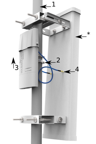
The Mounting hose clamp is provided with the package.
- Guide hose clamp through the opening on the back of the device and attach it to the mast.
- Align and secure with hose clamp screw using PH2 screwdriver.
- The device should be always placed by TOP cover facing upwards.
- Connect your antenna.
- Antenna is no provided with the device only for illustration purposes.
Grounding
The installation infrastructure (towers and masts), must be properly grounded.
Please secure all loose Ethernet cables and antenna cables to the pole or mast approximately at 30cm from the device, so that the cable weight is not pulling the ports and connectors.
Mounting using DIN rail
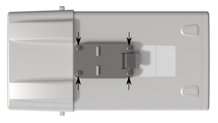
When mounting on DIN rail, please find special bracket in the package and secure it with four screws to the back of the unit. With attached mounting bracket you will be able to slide the device on the DIN rail.
Front status LED behavior
RouterOS allows configuring each LEDs activity the way that user wishes. It is possible to configure the LEDs to display wireless strength, blink the LEDs on interface traffic activity and many other options. For further information please visit https://wiki.mikrotik.com/wiki/Manual:System/LEDS
Default factory configuration for this device:
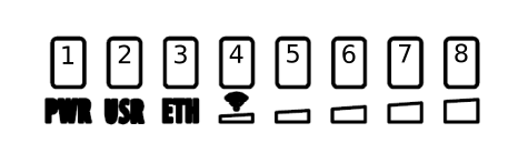
- Solid Blue – The device is powered on.
- Solid Green – User-defined LED.
- Solid Green – Active Ethernet port.
- 8. Solid Green – The set of five green LEDs, shows the signal strength.
Configuration
We recommend clicking the "Check for updates" button in the QuickSet menu, as updating your RouterOS software to the latest version ensures the best performance and stability. Please make sure you have selected the country where the device will be used, to conform with local regulations.
RouterOS includes many configuration options in addition to what is described in this document. We suggest starting here to get yourself accustomed to the possibilities: https://mt.lv/help. In case IP connection is not available, the Winbox tool (https://mt.lv/winbox) can be used to connect to the MAC address of the device from the LAN side (all access is blocked from the Internet port by default). Seek additional help from your local trainers or become a trainer of yourself. https://mikrotik.com/training/about
For recovery purposes, it is possible to boot the device for reinstallation, see section Buttons and Jumpers.
Reset button
The reset button has three functions:
- Hold this button during boot time until LED light starts flashing, release the button to reset RouterOS configuration (total 5 seconds).
- Keep holding for 5 more seconds, LED turns solid, release now to turn on CAP mode. The device will now look for a CAPsMAN server (total 10 seconds).
- Or Keep holding the button for 5 more seconds until LED turns off, then release it to make the RouterBOARD look for Netinstall servers (total 15 seconds).
Regardless of the above option used, the system will load the backup RouterBOOT loader if the button is pressed before power is applied to the device. Useful for RouterBOOT debugging and recovery.
Accessories
Package includes the following accessories that come with the device:
- EU/US Switching Power Supply 24 V DC ⎓, 0.8 A, 19.2 W.
- Hose clamp 40/60 w2 A2 9 mm.
- 2pcs - Plastic tie strap fastener (300 mm(L) 7,6 mm(W)).
- Gigabit POE injector cable with shielded connector (RBGPOE).
- K-27 din-rail bracket mounting set.
Antenna usage
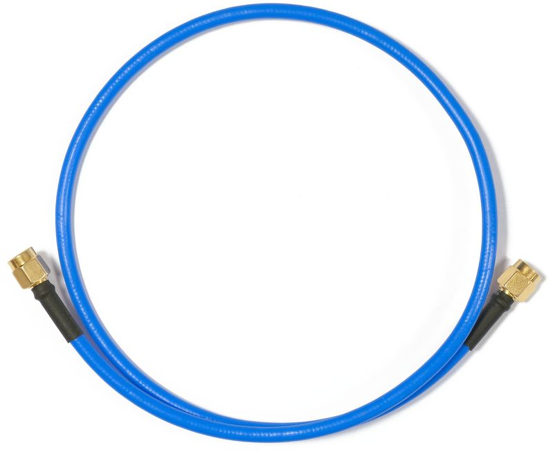
To connect to the external antenna please use, the "Flex-guide" - can be obtained separately. A super low loss 50cm long RPSMA cable for superior connection quality, suited for indoor and outdoor use, this cable provides superior matching and loss values. https://mikrotik.com/product/ACRPSMA
SMA connectors located under the upper cover (see "Removing upper cover") to access them.
Please connect and disconnect the antenna, when the device is turned off!
Wireless interface configuration information on the web: https://wiki.mikrotik.com/wiki/Manual:Interface/Wireless
Specifications
For more information about this product, specifications, pictures, downloads and test results please visit our web page: https://mikrotik.com/product/RB911G-5HPacD-NB
- RB911G-5HPacD-NB-US (USA) is factory locked for 5170-5250MHz and 5725-5835MHz frequencies. This lock can not be removed.
- RB911G-5HPacD-NB (International) supports 5150MHz-5875MHz range (Specific frequency range can be limited by country regulations).