Table of Contents
CRS3xx and CSS326-24G-2S+ series features
| Features | Description |
|---|---|
| Forwarding |
|
| Spanning Tree Protocol |
|
| Link Aggregation |
|
| Multicast Forwarding |
|
| Mirroring |
|
| VLAN |
|
| Security |
|
| Quality of Service (QoS) |
|
| Access Control List |
|
Models
This table clarifies the main differences between switch models.
| Model | Switch Chip | Serial console | Dual Boot | PoE-in support | PoE-out support | Health monitor |
CSS326-24G-2S+ | Marvell-98DX3216 | - | SwOS | ether1, Passive PoE | - | CPU temperature |
| CRS326-24G-2S+ | Marvell-98DX3236 | + | RouterOS/SwOS | ether1, Passive PoE | - | CPU temperature |
| CRS328-24P-4S+ | Marvell-98DX3236 | + | RouterOS/SwOS | - | ether1 - ether24, 802.3af/at | CPU and board temperature, fan speed, PSU voltage and current, PoE-out monitoring |
| CRS328-4C-20S-4S+ | Marvell-98DX3236 | + | RouterOS/SwOS | - | - | CPU temperature, fan speed, PSU state |
| CRS317-1G-16S+ | Marvell-98DX8216 | + | RouterOS/SwOS | - | - | CPU temperature, fan speed, PSU state |
| CRS305-1G-4S+ | Marvell-98DX3236 | - | RouterOS/SwOS | ether1, 802.3af/at | - | CPU temperature |
| CRS309-1G-8S+ | Marvell-98DX8208 | + | RouterOS/SwOS | ether1, 802.3af/at | - | CPU temperature |
| CRS312-4C+8XG | Marvell-98DX8212 | + | RouterOS/SwOS | - | - | CPU temperature, fan speed, PSU state |
| CRS326-24S+2Q+ | Marvell-98DX8332 | + | RouterOS/SwOS | - | - | CPU temperature, fan speed, PSU state |
| CRS318-16P-2S+ | Marvell-98DX226S | - | RouterOS/SwOS | - | ether1 - ether16, 802.3af/at | CPU temperature, PSU voltage and current, PoE-out monitoring. |
| CRS318-1Fi-15Fr-2S | Marvell-98DX224S | - | RouterOS/SwOS | ether1-ether14, ether16, Passive PoE | ether15, Passive PoE | CPU temperature |
| CRS354-48G-4S+2Q+ | Marvell-98DX3257 | + | RouterOS/SwOS | - | - | CPU and board temperature, fan speed, PSU voltage and current |
| CRS354-48P-4S+2Q+ | Marvell-98DX3257 | + | RouterOS/SwOS | - | ether1 - ether48, 802.3af/at | CPU and board temperature, fan speed, PSU voltage and current, PoE-out monitoring |
Connecting to the Switch
Open your web browser and enter the IP address of your switch (192.168.88.1 by default) and a login screen will appear. The switch can also run a DHCP client, see if a different IP address has been assigned by the DHCP server.
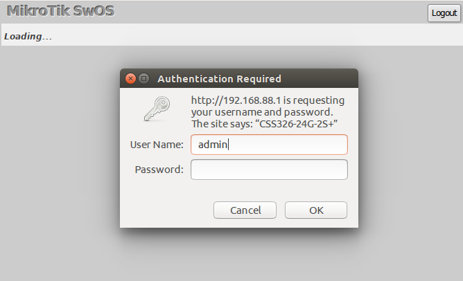
SwOS default IP address: 192.168.88.1, user name: admin and there is no password.
| Info |
|---|
MikroTik Neighbor Discovery can be used to discover the IP address of the Mikrotik switch. LLDP is not supported. |
Interface Overview
SwOS interface menu consists of multiple tabs depending on the device model. These are all possible SwOS menus: Link, PoE, SFP, Port Isolation, LAG, Forwarding, RSTP, Stats, Errors, Hist, VLAN, VLANs, Hosts, IGMP, SNMP, ACL, System, Health and Upgrade.
Description of buttons in SwOS configuration tool:
- Append - add a new item to the end of the list
- Apply All - applies current configuration changes
- Boot RouterOS - boot device into RouterOS
- Cut - removes an item from the list
- Clear - reset properties of the item
- Discard Changes - removes unsaved configuration
- Insert - add a new item to the list (places it before current item)
- Sort - sort VLAN table by VLAN-IDs; sort host table by MAC addresses
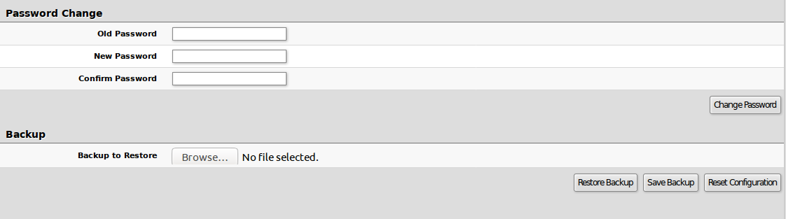
- Change Password - changes the password of the switch
- Logout - logout from the current switch
- Reboot - reboot the switch
- Reset Configuration - reset configuration back to factory defaults
- Choose File - browse for upgrade or backup file
- Upgrade - upgrade the firmware of the switch using the selected file
- Download & Upgrade - automatically try to download and upgrade the firmware, the PC which is running a web browser should be able to access the Internet
- Restore Backup - restore switch using a selected backup file
- Save Backup - generate and download the backup file from the switch
| Info |
|---|
Each RouterBoard switch series device has its own firmware which cannot be installed on other series models!
|
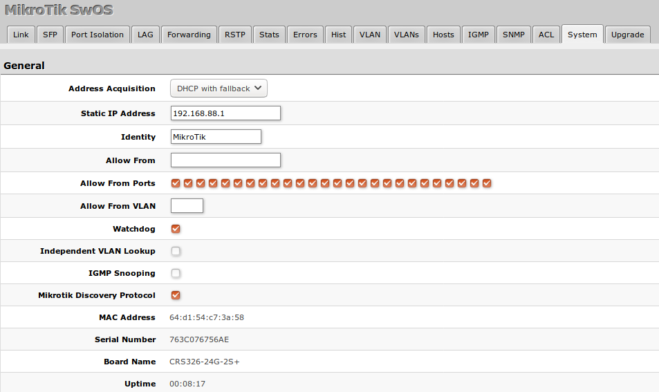
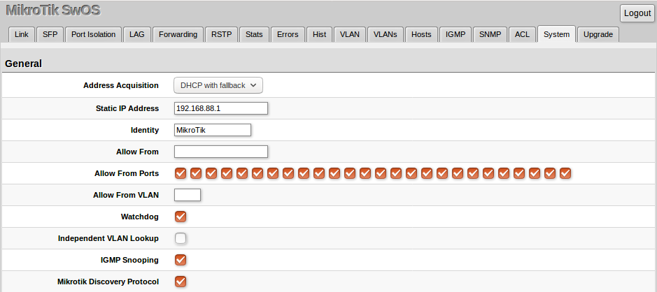
System
System Tab performs the following functions:
- General information about switch
- Switch management
- Configuration reset
- Backup and restore configuration
| Info |
|---|
SwOS uses a simple algorithm to ensure TCP/IP communication - it just replies to the same IP and MAC address packet came from. This way there is no need for Default Gateway on the device itself. |
| Property | Description |
|---|---|
| Address Acquisition | Specify which address acquisition method to use:
|
| Static IP Address | IP address of the switch in case of Address Acquisition is set as DHCP with fallback or static |
| Identity | Name of the switch (for Mikrotik Neighbor Discovery protocol) |
| Allow From | IP address from which the switch is accessible. Default value is '0.0.0.0/0' - any address |
| Allow From Ports | List of switch ports from which it is accessible |
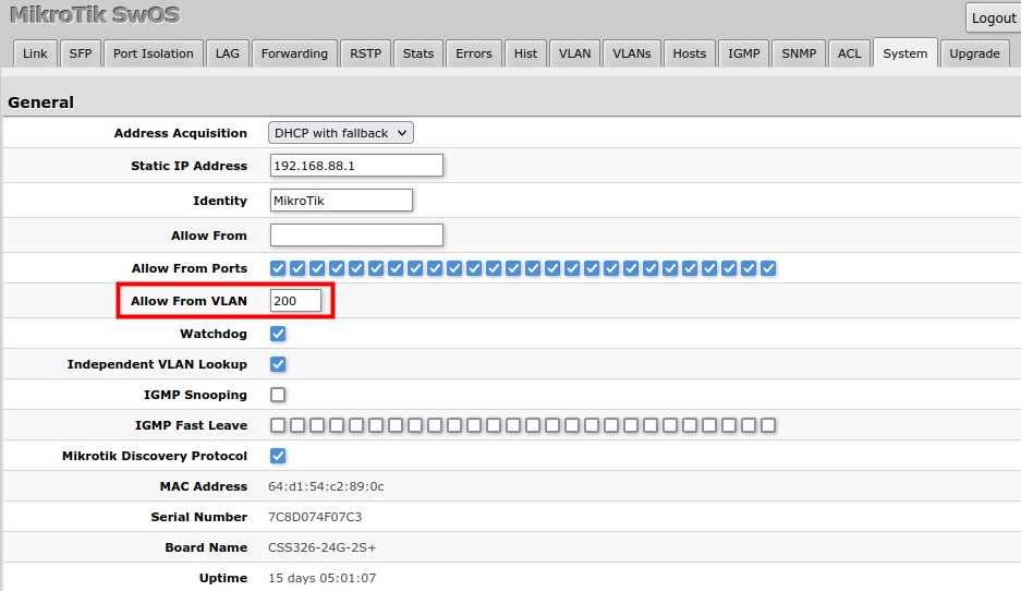
| Allow From VLAN | VLAN ID from which the service is accessible. Make sure to first configure VLANs and VLAN pages |
| Watchdog | Enable or disable system Watchdog. It will reset CPU of the switch in case of fault condition |
| Independent VLAN Lookup | Enable or disable independent VLAN lookup in the Host table for packet forwarding |
| IGMP Snooping | Enable or disable IGMP Snooping |
| IGMP Fast Leave | Enables or disables IGMP fast leave feature on the switch port. This property only has an effect when IGMP Snooping is enabled. |
| Mikrotik Discovery Protocol | Enable or disable Mikrotik Neighbor Discovery protocol |
| MAC Address | MAC address of the switch (read-only) |
| Serial Number | Serial number of the switch (read-only) |
| Board Name | MikroTik model name of the switch (read-only) |
| Uptime | Current switch uptime (read-only) |
| Temperature | Shows CPU temperature in celsius temperature scale (read-only, CSS326-24G-2S+, CRS326-24G-2S+, CRS305-1G-4S+, CRS309-1G-8S+, CRS318-1Fi-15Fr-2S models only) |
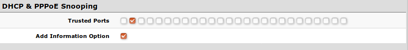
DHCP & PPPoE Snooping
| Property | Description |
|---|---|
| Trusted Ports | Group of ports, which allows DHCP or PPPoE servers to provide a requested information. When enabled, it allows forwarding DHCP client packets towards the DHCP server through this port. Mainly used to limit unauthorized servers to provide malicious information for users, access ports usually do not configure as trusted. Ports that receive DHCP client packets with already added Option-82 must also be trusted, otherwise these packets are dropped. |
| Add Information Option | Enables or disables DHCP Option-82 information. When enabled, the Option-82 information (Agent Remote ID and Circuit ID) is added for DHCP packets received from untrusted ports. Can be used together with Option-82 capable DHCP server to assign IP addresses and implement policies. For Agent Remote ID, SwOS uses interface name where DHCP client resides. For Agent Circuit ID, SwOS uses identity of the SwOS device, internally used port ID and VLAN ID. For example: Agent Remote ID - Port1 Agent Circuit ID - MikroTik eth 0/1:100 |
Password and Backup
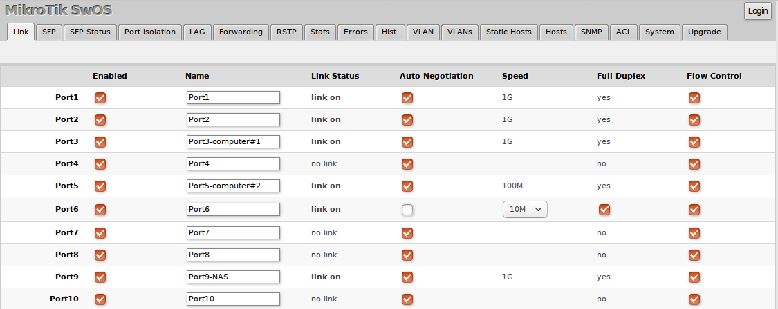
Link
Link Tab allows you to configure each interface settings and monitor the link status.
| Property | Description |
|---|---|
| Enabled | Enable or disable port |
| Name | Editable port name |
| Link Status | Current link status (read-only) |
| Auto Negotiation | Enable or disable auto-negotiation |
| Speed | Specify speed setting of the port (requires auto-negotiation to be disabled) |
| Full Duplex | Specify the duplex mode of the port (requires auto-negotiation to be disabled) |
| Flow control Tx/Rx | Enable or disable 802.3x Flow control |
| Info |
|---|
The switch supports Jumbo frames up to 10218 bytes. Manually decreasing the MTU settings is not supported for SwOS devices. |
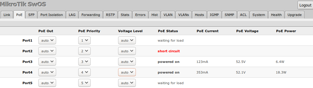
PoE
Devices with PoE-out support have some configuration options and certain monitoring features, like PoE-out current, voltage, etc. For more details about PoE, see the PoE-Out manual.
Property | Description |
|---|---|
| PoE Out | Specifies PoE-Out state:
|
| PoE Priority | The PoE Priority specifies the importance of PoE-Out ports, in cases when a total PoE-Out limit is reached, interface with the lowest port priority will be powered off first. Highest priority is 1, lowest priority is 8. If there are 2 or more ports with the same priority then port with the smallest port number will have a higher priority. For example, if ether2 and ether3 have the same priority and over-current is detected then PoE-Out on ether3 will be turned off. Every 6 seconds ports will be checked for a possibility to provide PoE-Out if it was turned off due to port priority. |
| Voltage Level | Feature which allows to manually switch between two voltage outputs on PoE-Out ports. Will take effect only on PSE with switchable voltage modes (CRS328-24P-4S+RM, netPower 16P, CRS354-48P-4S+2Q+RM). |
| PoE Status | Shows current PoE-Out status on port:
The delivered voltage at PD is too low for normal powering (for example Vmin =>30V, but provided 24V); PD uses a second power source which has a higher voltage than PSE, so all current is taken from the second DC source, not PSE PoE-Out port. |
| PoE Current | Shows current usage on the port measured in milliamperes |
| PoE Voltage | Shows voltage on the port measured in volts |
| PoE Power | Shows PoE out power on the port measured in watts |
| Info |
|---|
If the Voltage Level is set to "auto" and PoE Out is set to "on", the low voltage will be used by default. If the PD supports only high voltage, make sure you also set Voltage Level to "high" when forcing the PoE output. |
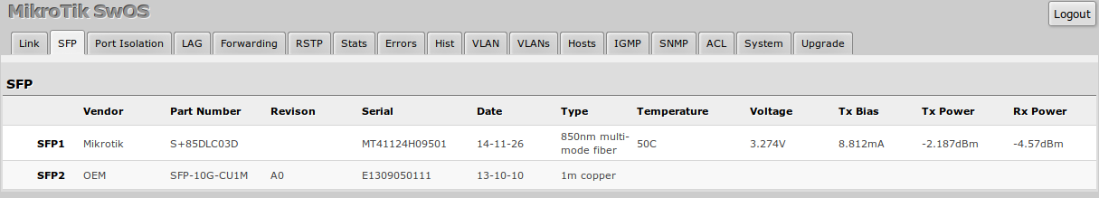
SFP
SFP tab allows you to monitor the status of SFP/SFP+ modules.
Port Isolation
The Port Isolation table allows or restricts traffic forwarding between specific ports. By default, all available switch chip ports can communicate with any other port, there is no isolation used. When the checkbox is enabled/ticked you allow to forward traffic from this port towards the ticked port. Below are some port isolation examples.
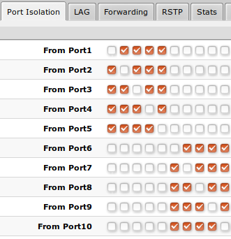
In some scenarios, you might need to isolate a group of devices from other groups. In this example devices on Port1-Port5 are not able to communicate with Port6-Port10 devices, and vice versa.
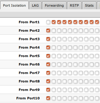
In some scenarios, you might need to forward all traffic to an uplink port while all other ports are isolated from each other. This kind of setup is called a Private VLAN configuration. The switch will forward all Ethernet frames only to the uplink Port1, while uplink can reach all other ports
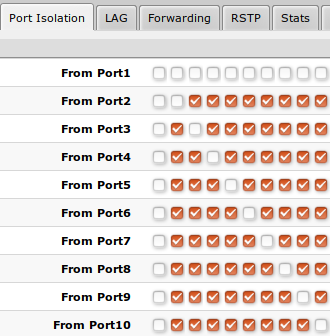
Individual isolated Port1 (e.g. for management purpose), it cannot send or receive traffic from any other port
| Info |
|---|
It is possible to check/uncheck multiple checkboxes by checking one of them and then dragging horizontally (Click & Drag). |
| Info |
|---|
(R)STP will only work properly in Private VLAN setups. In setups with multiple isolated switch groups (R)STP might not properly receive BPDUs and therefore fail to detect network loops. |
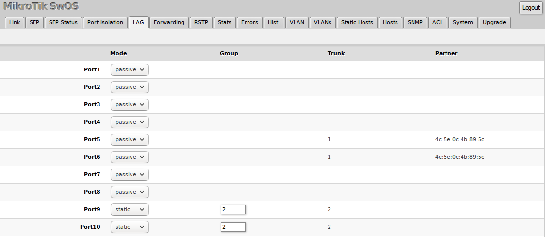
LAG
IEEE 802.3ad (LACP) compatible link aggregation is supported, as well as static link aggregation to ensure failover and load balancing based on Layer2, Layer3 and Layer4 hashing. Up to 16 link aggregation groups with up to 8 ports per group are supported. Each individual port can be configured as Passive LACP, Active LACP, or a Static LAG port.
| Property | Description |
|---|---|
| Mode (default: passive) | Specify LACP packet exchange mode or Static LAG mode on ports:
|
| Group | Specify a Static LAG group. |
| Trunk (read-only) | Represents group number port belongs to. |
| Partner (read-only) | Represents partner mac-address, only available when ports are included in LACP. |
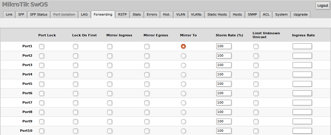
Forwarding
Forwarding Tab provides advanced forwarding options among switch ports, port locking, port mirroring, bandwidth limit, and broadcast storm control features.
| Property | Description |
|---|---|
| Port Lock |
|
| Port Mirroring |
|
| Broadcast Storm Control |
|
| Multicast Flood Control |
|
| Bandwidth Limit |
|
| Info |
|---|
It is possible to limit ingress traffic per-port basis with traffic policer. The ingress policer controls the received traffic with packet drops. Everything that exceeds the defined limit will get dropped. This can affect the TCP congestion control mechanism on end hosts and achieved bandwidth can be actually less than defined. |
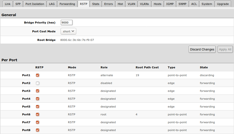
RSTP
Per-port and global RSTP configuration and monitoring are available in the RSTP menu.
| Property | Description |
|---|---|
| Bridge Priority (hex) | RSTP bridge priority for Root Bridge selection |
| Port Cost Mode | There are two methods for automatically detecting RSTP port cost depending on link speed.
|
| Root Bridge | The priority and MAC address of the selected Root Bridge in the network (read-only) |
| RSTP | Enable or disable STP/RSTP functionality on this port |
| Mode | Shows STP/RSTP functionality mode on a specific port (read-only):
|
| Role | Shows specific port role (read-only):
|
| Root Path Cost | Shows root path cost for ports that are facing root bridge (read-only) |
| Type |
|
| State | Shows each port state (read-only):
|
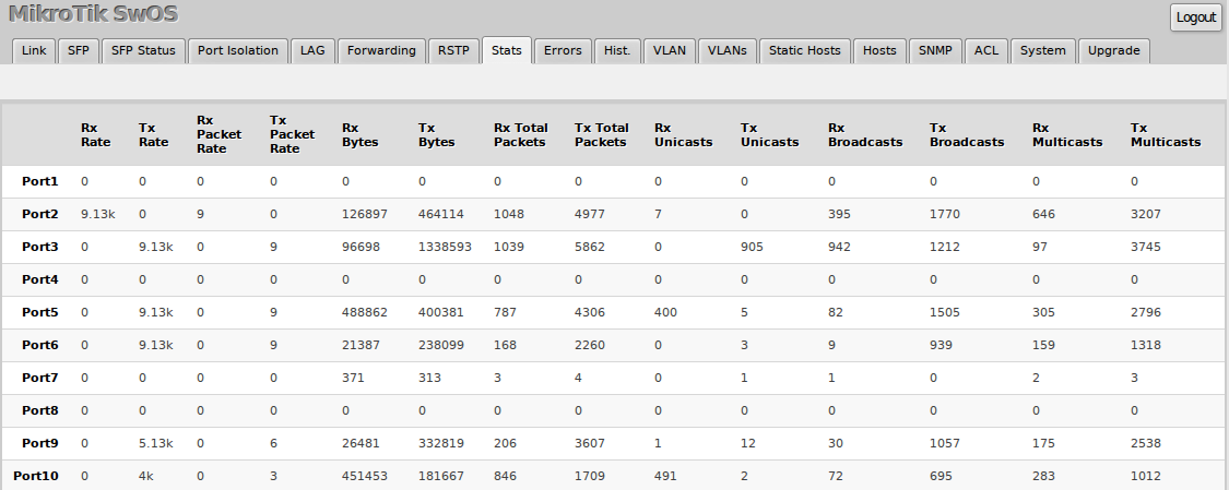
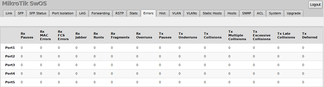
Stats, Errors and Histogram
These menus provide detailed information about received and transmitted packets.
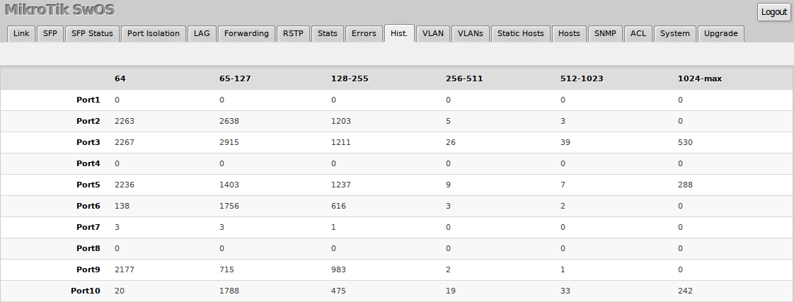
| Info |
|---|
Statistics for SFP+ interface are cleared whenever an active SFP+ link is established. |
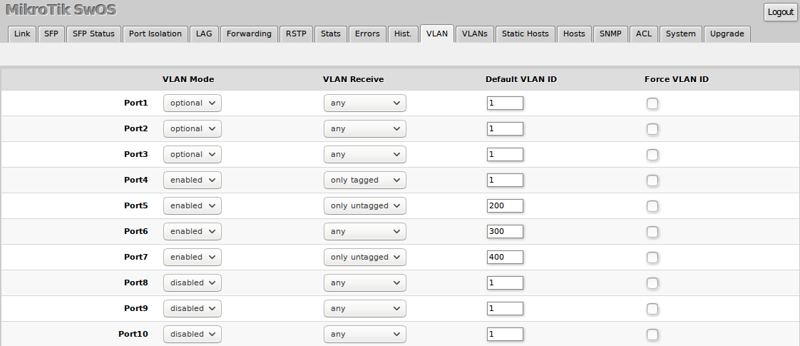
VLAN and VLANs
VLAN configuration for switch ports.
| Property | Description |
|---|---|
| VLAN Mode (disabled | optional | enabled | strict; Default: optional) | VLAN filtering mode, these options are relevant to egress ports (except for strict mode).
|
| VLAN Receive (any | only tagged | only untagged; Default: optional) | Received traffic filtering based on VLAN tag presence.
|
| Default VLAN ID (integer: 1..4095; Default: 1) | The switch will place received untagged packets in the "Default VLAN ID" VLAN. Only has an effect on untagged traffic, and when VLAN Receive is set to "any" or "only untagged". It does not apply for tagged traffic. This parameter is usually used to allocate access ports with specific VLAN. It is also used to untag egress traffic if the packet's VLAN ID matches Default VLAN ID. |
| Force VLAN ID (integer: yes | no; Default: no) | Assigns the Default VLAN ID value to all ingress traffic (tagged and untagged). Has effect in all VLAN Modes. If the port receives tagged traffic and Default VLAN ID is set to 1, then with this parameter the egress traffic will be untagged. |
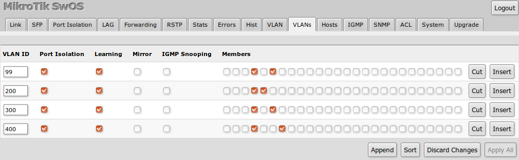
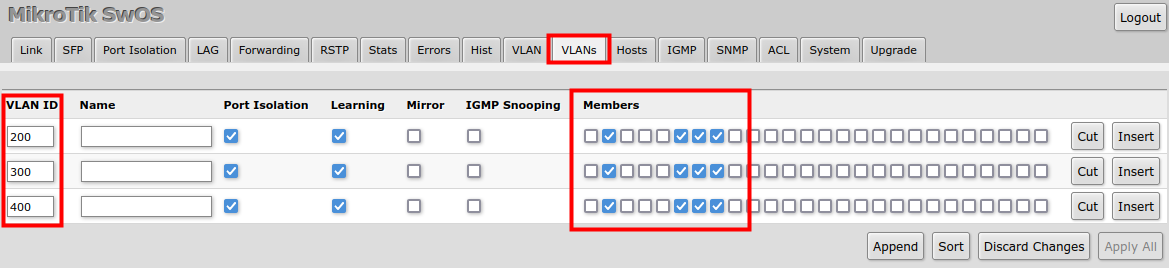
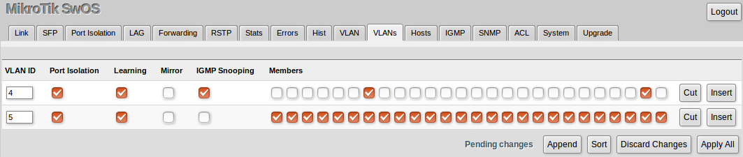
VLAN membership configuration for switch ports.
| Property | Description |
|---|---|
| VLAN ID (integer: 1..4095; Default: 0) | VLAN ID to which assign ports. |
| Name (text; Default: ) | Short description of the VLAN. |
| Port Isolation (yes | no; Default: yes) | Use settings from Port Isolation menu to isolate the defined VLAN to only certain ports. When disabled, the switch will ignore port isolation configuration and forward traffic with the defined VLAN ID only to ports that are checked as members. |
| Learning (yes | no; Default: yes) | Enables or disables MAC address learning on the defined VLAN. If disabled, then all learned MAC addresses will appear as they have had been learned from VLAN 1. |
| Mirror (yes | no; Default: no) | Enables or disables VLAN-based mirroring. When enabled and Mirror To is set in the Forwarding menu, then all traffic from the defined VLAN will be mirrored to the selected port. |
| IGMP Snooping (yes | no; Default: no) | Enables or disables IGMP Snooping on the defined VLAN. When enabled, the switch will listen to IGMP Join and Leave requests from the defined VLAN and only forward traffic to ports, which have sent IGMP membership requests from the defined VLAN. When disabled, the switch will flood all VLAN member ports with Multicast traffic. |
| Members (ports; Default: none) | Group of ports, which are allowed to forward traffic on the defined VLAN. |
VLAN Configuration Example
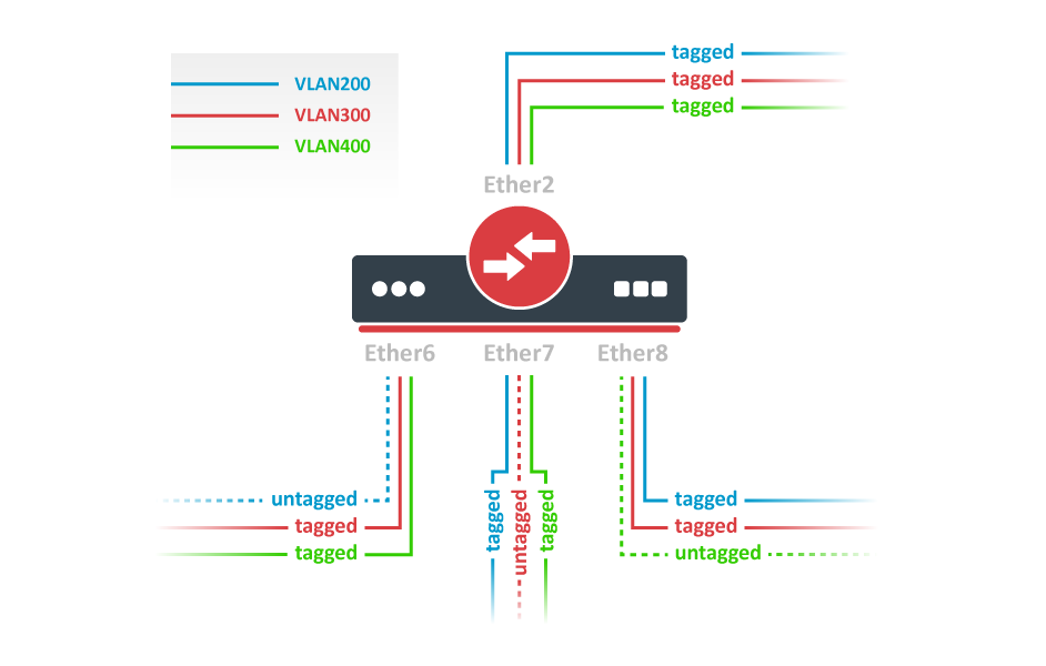
Trunk and Access Ports
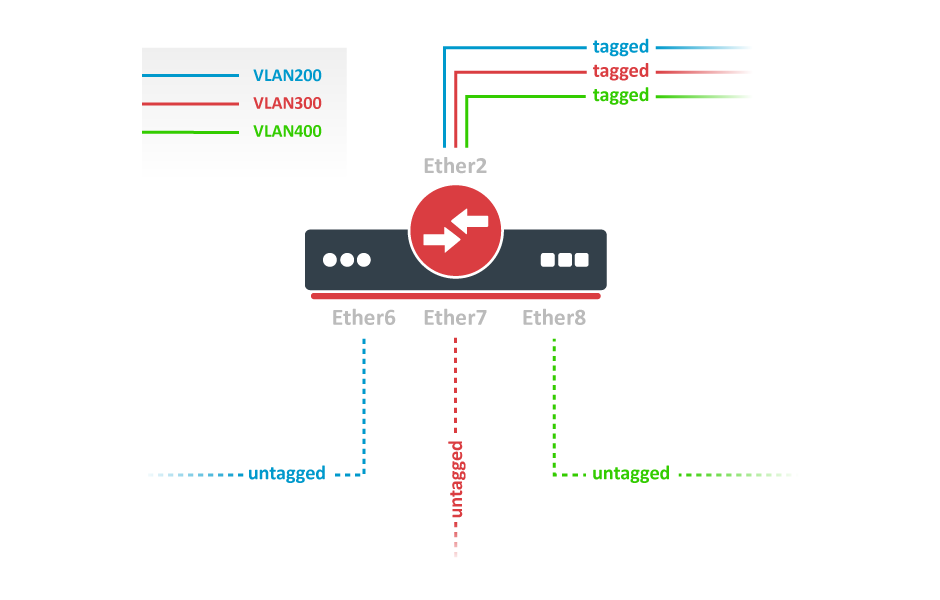
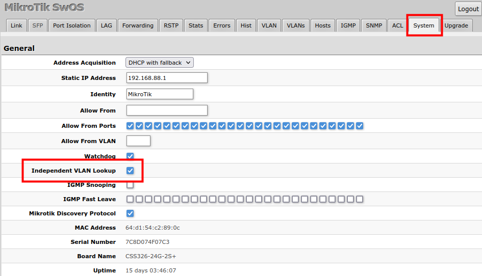
1. In the System menu enable independent VLAN learning (IVL).
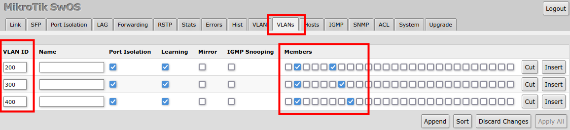
2. In the VLANs menu add VLAN entries and specify port membership.
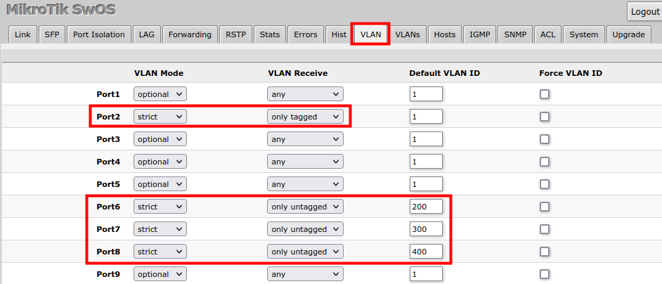
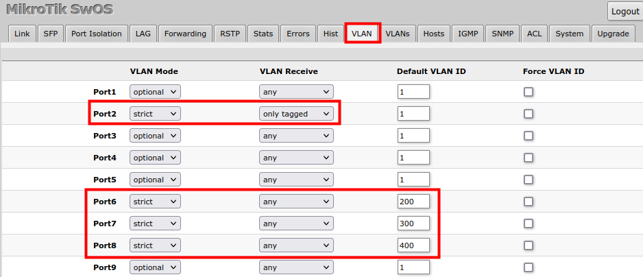
3. In the VLAN menu configure Default VLAN ID on planned access ports (untagged), select the correct VLAN Receive setting (Port2 only tagged, Port6-8 only untagged) and enable strict VLAN filtering to ensure only allowed VLANs can pass through the ports.
Trunk and Hybrid Ports
1. In the System menu enable independent VLAN learning (IVL).
2. In the VLANs menu add VLAN entries and specify port membership.
3. In the VLAN menu configure Default VLAN ID on planned hybrid ports (for untagged VLAN), select the correct VLAN Receive setting (Port2 only tagged, Port6-8 any) and enable strict VLAN filtering to ensure only allowed VLANs can pass through the ports.
Management access
In this example, switch management access on VLAN 200 will be created. The configuration scheme is the same as "Trunk and Access Ports" and 1., 2., 3. configuration steps are identical. The additional 4th step requires to specify the management VLAN ID in the System menu. After applying the configuration, switch will only respond to tagged VLAN 200 packets on Port2 and untagged packets on Port6. The DHCP client will also work in the specified VLAN ID.
| Note |
|---|
Changing management VLAN can completely disable access to the switch management if VLAN settings are not correctly configured. Save a configuration backup before changing this setting and use Reset in case management access is lost. |
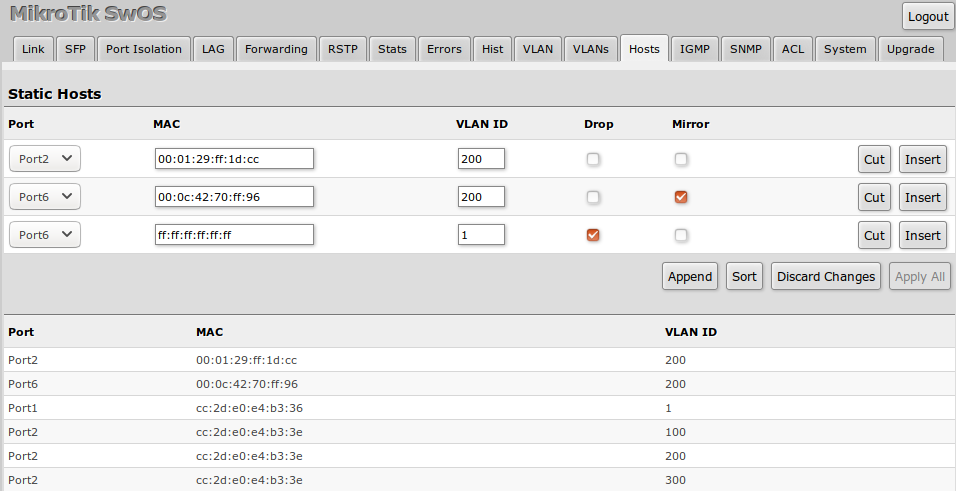
Hosts
This table represents dynamically learned MAC address to port mapping entries. It can contain two kinds of entries: dynamic and static. Dynamic entries get added automatically, this is also called a learning process: when a switch receives a packet from a certain port, it adds the packet's source MAC address and port it received the packet from to the host table, so when a packet comes in with a certain destination MAC address it knows to which port it should forward the packet. If the destination MAC address is not present in the host table then it forwards the packet to all ports in the group. Dynamic entries take about 5 minutes to time out.
Static entries will take over dynamic if dynamic entry with same mac-address already exists. Also by adding a static entry you get access to more functionality.
| Property | Description |
|---|---|
| Ports | Ports the packet should be forwarded to |
| MAC | MAC address |
| VLAN ID | VLAN ID |
| Drop | A packet with certain MAC address coming from certain ports can be dropped |
| Mirror | A packet can be cloned and sent to mirror-target port |
| Port (read-only) | Ports the packet should be forwarded to |
| MAC(read-only) | Learned MAC address |
| VLAN ID (read-only) | Learned VLAN ID |
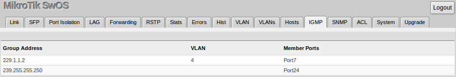
IGMP Snooping
IGMP Snooping which controls multicast streams and prevents multicast flooding is implemented in SwOS starting from version 2.5. The feature allows a switch to listen in the IGMP conversation between hosts and routers.
Enable this option under the System tab. Since SwOS 2.13 version, IGMP Fast Leave option can also be configured.
Available IGMP snooping data can be found under the IGMP tab.
It is possible to enable IGMP Snooping for a specific VLAN ID under the VLANs menu.
| Info |
|---|
IGMP Snooping for VLANs requires enabled "Independent VLAN Lookup" in the System menu. |
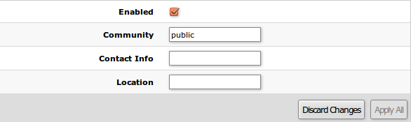
SNMP
SwOS supports SNMP v1 and uses IF-MIB, SNMPv2-MIB, BRIDGE-MIB and MIKROTIK-MIB (only for health, PoE-out and SFP diagnostics).
Available SNMP data:
- System information
- System uptime
- Port status
- Interface statistics
- Host table information
| Property | Description |
|---|---|
| Enabled | Enable or disable SNMP service |
| Community | SNMP community name |
| Contact Info | Contact information for the NMS |
| Location | Location information for the NMS |
ACL Tab
An access control list (ACL) rule table is a very powerful tool allowing wire-speed packet filtering, forwarding, and VLAN tagging based on L2,L3, and L4 protocol header field conditions. Each rule contains a conditions part and an action part.
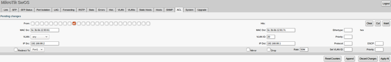
Conditions part parameters
| Property | Description |
|---|---|
| From | A port that packet came in from |
| MAC Src | Source MAC address and mask |
| MAC Dst | Destination MAC address and mask |
| Ethertype | Protocol encapsulated in the payload of an Ethernet Frame |
| VLAN | VLAN header presence:
|
| VLAN ID | VLAN tag ID |
| Priority | Priority in VLAN tag |
| IP Src (IP/netmask:port) | Source IPv4 address, netmask, and L4 port number |
| IP Dst (IP/netmask:port) | Destination IPv4 address, netmask, and L4 port number |
| Protocol (integer) | IP protocol |
| DSCP | IP DSCP field |
Action part parameters
| Property | Description |
|---|---|
| Redirect To | Force new packets destination port |
| Mirror | Clones packet and sends it to mirror-target port |
| Rate | Limits bandwidth (bps) |
| Drop | Drop packet |
| Set VLAN ID | Changes the VLAN tag ID, if VLAN tag is present |
| Priority | Changes the VLAN tag priority bits, if VLAN tag is present |
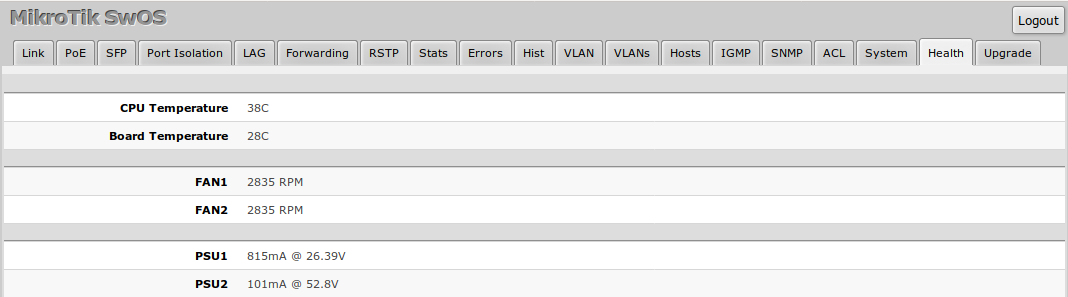
Health
This menu provides different health-related properties.
| Property | Description |
|---|---|
| CPU Temperature | Shows CPU temperature in celsius temperature scale (read-only) |
| Board Temperature | Shows PCB temperature in celsius temperature scale (read-only) |
| FAN | Shows FAN rotational speed (read-only) |
| PSU | Shows PSU related information depending on device model (read-only):
|
| Info |
|---|
For devices with only a CPU temperature sensor (CRS326-24G-2S+, CRS305-1G-4S+, CRS309-1G-8S+, CRS318-1Fi-15Fr-2S) health information is available under System menu. |
Configuring SwOS using RouterOS
Since RouterOS 6.43 it is possible to load, save and reset SwOS configuration, as well as upgrade SwOS and set an IP address for the switch by using RouterOS. For more details see this article - Configuring SwOS using RouterOS
| Info |
|---|
This option is not available for the CSS326-24G-2S+ device. |
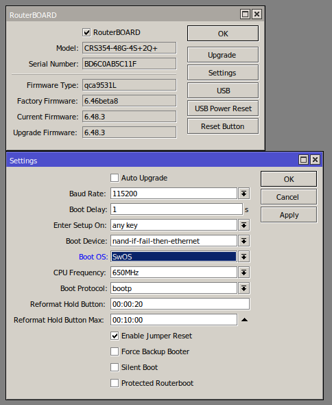
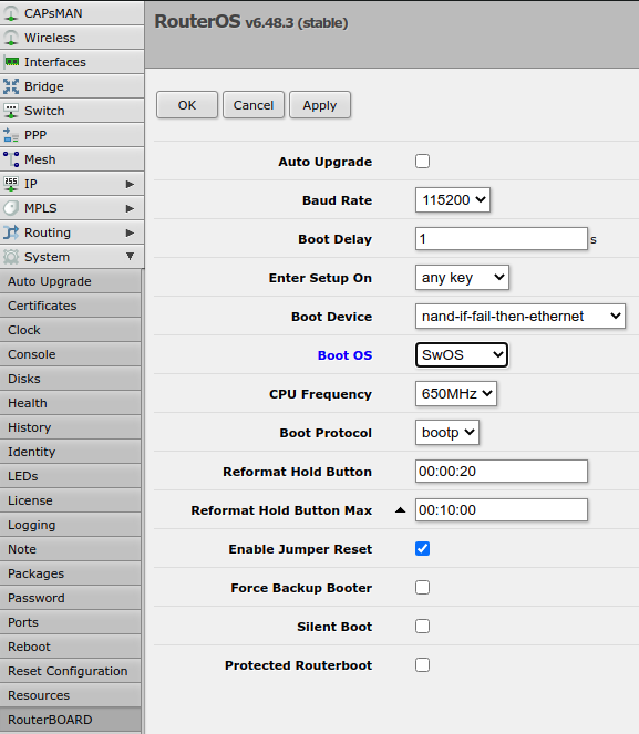
Dual Boot
The “Dual Boot” feature allows you to choose which operating system you prefer to use, RouterOS or SwOS. You can boot RouterOS under the System menu with the "Boot RouterOS" button.
Different options are available to change the operating system to SwOS:
- Change boot settings in RouterOS using command-line (
/system routerboard settings set boot-os=swos) and reboot (/system reboot) - Change boot settings in RouterOS using WinBox or WebFig and reboot
- Change boot settings during device booting from a serial console
| Info |
|---|
These options are not available for the CSS326-24G-2S+ device. |
Reset and Reinstall
It is possible to reset SwOS configuration using the "Reset Configuration" button in the System menu. In case SwOS web management in not available, the configuration can still be reset using other options.
The CSS326-24G-2S+ device has built-in backup SwOS firmware which can be loaded in case standard firmware breaks or upgrade fails:
- Holding Reset button for few seconds while CSS326-24G-2S+ is booting resets configuration and loads backup firmware.
- After loading backup firmware, it is possible to connect to 192.168.88.1 (or leased address from a DHCP server) using web browser and install new SwOS firmware.
The Dual Boot devices can boot RouterOS using a reset button. Power the device while holding the reset button and wait till user LED starts flashing (around 5 seconds). This will reset the RouterOS configuration and the device will now boot into RouterOS. After device is accessable by RouterOS, it is possible to upgrade and reset SwOS configuration. See the article - Configuring SwOS using RouterOS.
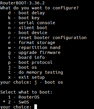
CRS3xx devices with a serial console have additional options.
To change between RouterOS and SwOS follow these steps:
- Connect to the device using a serial console
- Enter RouterBOOT setup
- Choose "j - boot os"
- Choose either RouterOS or SwOS
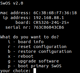
It is possible to load a SwOS backup firmware in case standard firmware breaks or upgrade fails:
- Connect to the device using a serial console
- Boot SwOS
- Choose "p - boot primary SwOS"
- After loading backup firmware, it is possible to connect to 192.168.88.1 (or leased address from a DHCP server) using a web browser and install new SwOS firmware.
To reset SwOS configuration:
- Connect to the device using a serial console
- Boot SwOS
- Choose "r - reset configuration"