...
There are certain configurations that are known to have major flaws by design and should be avoided by all means possible. Misconfigured Layer2 can sometimes cause hard to detect network errors, random performance drops, certain segments of a network to be unreachable, certain networking services to be malfunctioning, or a complete network failure. This page will contain some common and not so very common configurations that will cause issues in your network.
...
After a simple performance test, you might notice that one bridge is capable of forwarding traffic at wire - speed while the second, third, etc. bridge is not able to forward as much data as the first bridge. Another symptom might be that there exists a huge latency for packets that need to be routed. After a quick inspection, you might notice that the CPU is always at full load, this is because hardware offloading is not available on all bridges, but is available only on one bridge. By checking the hardware offloading status you will notice that only one bridge has it active:
...
The reason why only one bridge has the hardware offloading flag available is because that the device does not support port isolation. If port isolation is not supported, then only one bridge will be able to offload the traffic to the switch chip.
...
Below is a list of possible symptoms that might be as a result of this kind of a misconfiguration:
- Missing "H" flag to bridge ports
- Low throughput
- High CPU usage
...
Not all device devices support port isolation, currently only CRS1xx/CRS2xx series devices support it and only 7 isolated and hardware offloaded bridges are supported at the same time, other devices will have to use the CPU to forward the packets on other bridges. This is usually a hardware limitation and a different device might be required. Bridge split-horizon parameter is a software feature that disables hardware offloading and when using bridge filter rules you need to enable forward all packets to the CPU, which requires the hardware offloading to be disabled. You can control which bridge will be hardware offloaded with the hw=yes flag and by setting hw=no to other bridges, for example:
...
When running Sniffer or Torch tools to capture packets you might notice that barely any packets are visible, only some unicast packets, but mostly broadcast/multicast packets are captured, while the interfaces report that much larger traffic is flowing through certain interfaces than the traffic that was captured. Since RouterOS v6.41 if you add two or more Ethernet interfaces to a bridge and enable Hardware Offloading, then the switch chip will be used to forward packets between ports. To understand why only some packets are captured, we must first examine how the switch chip is interconnected with the CPU, in this example, we can use a block diagram from a generic 5-Port Ethernet router:
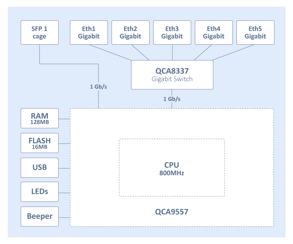
For this device, each Ethernet port is connected to the switch chip and the switch chip is connected to the CPU using the CPU port (sometimes called the switch-cpu port). For packets to be visible in Sniffer or Torch tools, the packet must be sent from an Ethernet port to the CPU port, this means that the packet must be destined to the CPU port (destination MAC address of the packet matches the bridge's MAC address) or the packet's MAC address has not be learnt (packet is flooded to all ports), this behavior is because of MAC learning·
...
Below is a list of possible symptoms that might be as a result of this kind of a misconfiguration:
...
Packets with a destination MAC address that has been learned will not be sent to the CPU since the packets are not being flooded to all ports. If you do need to send certain packets to the CPU for a packet analyzer or a firewall, then it is possible to copy or redirect the packet to the CPU by using ACL rules. Below is an example of how to send a copy of packets that are meant for 4C:5E:0C:4D:12:4B:
...
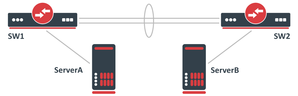
Consider the following scenario, you have created a LAG interface to increase total bandwidth between 2 network nodes, usually, these are switches. For testing purposes to make sure that the LAG interface is working properly you have attached two servers that transfer data, most commonly the well-known network performance measurement tool https://en.wikipedia.org/wiki/Iperf is used to test such setups. For example, you might have made a LAG interface out of two Gigabit Ethernet ports, which gives you a 2Gbps interface while the servers are connected using a 10Gbps interface, for example, SFP+.
Configuration
...
Below is a list of possible symptoms that might be as a result of this kind of a misconfiguration:
- Traffic going through only one LAG member
...
Below is a list of possible symptoms that might be as a result of this kind of a misconfiguration:
- DHCP Client/Server not working properly;
- Device is unreachable;
- Device The device behind a bridge is unreachable with tagged traffic;
Solution
Change the interface on which the VLAN interface will be listening for traffic, change it to the master interface:
...
Consider the following scenario, you have a set of interfaces (don't have to be physical interfaces) and you want all of them to be in the same Layer2 segment, the solution is to add them to a single bridge, but you require that traffic from one port tags all traffic into a certain VLAN. This can be done by creating a VLAN interface on top of the bridge interface and by creating a separate bridge that contains this newly created VLAN interface and an interface, which is supposed to add a VLAN tag to all received traffic. A network diagram can be found below:
Configuration
...
To better understand the underlying problems, lets let's first look at the bridge host table.
...
Below is a list of possible symptoms that might be as a result of this kind of a misconfiguration:
- Port blocked by RSTP
- Loops in network
- Port flapping
- Traffic is flooded to all ports
- MAC telnet is unable to connect
- Device inaccessible
...
Use bridge VLAN filtering. The proper way to tag traffic is to assign a VLAN ID whenever traffic enters a bridge, this behavior can easily be achieved by specifying PVID value for a bridge port and specifying which ports are tagged (trunk) ports and which are untagged (access) ports. Below is an example of how such a setup should have been configured:
...
Below is a list of possible symptoms that might be as a result of this kind of a misconfiguration:
- Port blocked by RSTP
- Loops in network
- Port flapping
- Traffic stops forwarding over time
- BPDUs ignored by other RSTP enabled devices
...
To avoid compatibility issues you should use bridge VLAN filtering. Below you can find an example of how the same traffic tagging effect can be achieved with a bridge VLAN filtering configuration:
...
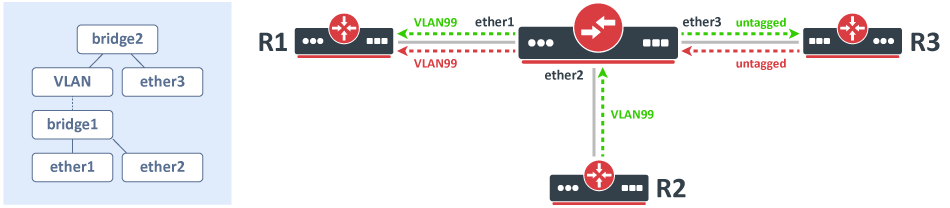
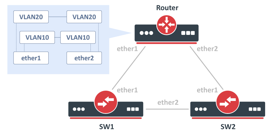
A very similar case to VLAN on a bridge in a bridge, consider the following scenario, you have a couple of switches in your network and you are using VLANs to isolate certain Layer2 domains and connect these switches to a router that assigns addresses and routes the traffic to the world. For redundancy, you connect all switches directly to the router and have enabled RSTP, but to be able to setup DHCP Server you decide that you can create a VLAN interface for each VLAN on each physical interface that is connected to a switch and add these VLAN interfaces in a bridge. A network diagram can be found below:
Configuration
...
Below is a list of possible symptoms that might be as a result of this kind of a misconfiguration:
- Port blocked by (R)STP;
- Loops in network;
- Low throughput;
- Port flapping;
- Network inaccessible;
Solution
A solution is to use bridge VLAN filtering in order to make all bridges compatible with IEEE 802.1W and IEEE 802.1Q.
...
Below is a list of possible symptoms that might be as a result of this kind of a misconfiguration:
- Port blocked by (R)STP;
- Port flapping;
- Network inaccessible;
Solution
The easiest solution is to simply disable (R)STP on the bridge:
...
Below is a list of possible symptoms that might be as a result of this kind of a misconfiguration:
- Missing "H" flag on bridge ports
- Low throughput
- High CPU usage
...
Before using bridge VLAN filtering check if your device supports it at the hardware level, a table with compatibility can be found at the Bridge Hardware Offloading section. Each type of device currently requires a different configuration method, below is a list of which configuration should be used on a device in order to use the benefits of hardware offloading:
...
Consider the following scenario, you have a device with two or more switch chips and you have decided to use a single bridge and setup set up VLAN filtering (by using the /interface ethernet switch menu) on a hardware level to be able to reach wire-speed performance on your network. This is very relevant for RB2011 and RB3011 series devices. In this example, let's assume that you want to have a single trunk port and all other ports are access ports, for example, ether10 is our trunk port and ether1-ether9 are our access ports.
...
Below is a list of possible symptoms that might be as a result of this kind of a misconfiguration:
- Packets being dropped;
- Low throughput;
Solution
The proper solution is to take into account this hardware design and plan your network topology accordingly. To solve this issue you must create two separate bridges and configure VLAN filtering on each switch chip, this limits the possibility to forward packets between switch chip, though it is possible to configure routing between both bridges (if devices that are connected on each switch chip are using different network subnets).
There is a way to configure the device to have all ports switch together and yet be able to use VLAN filtering on a hardware level, though this solution has some caveats. The idea is to sacrifice a single Ethernet port on each switch chip that will act as a trunk ports port to forward packets between switch chip, this can be done by plugging an Ethernet cable between both switch chip, for example, lets plug in an Ethernet cable between ether5 and ether6 then reconfigure your device assuming that these ports are trunk ports:
...
You need to create a network setup where multiple clients are connected to separate access ports and isolated by different VLANs, this traffic should be tagged and sent to the appropriate trunk port. Access ports are configured using a pvid property. As the trunk port is used on both VLANs, you decided to simplify configuration by adding a single bridge VLAN table entry and separate VLANs by a comma. This is especially useful when tagged trunk ports are used across large numbers of VLANs or even certain VLAN ranges (e.g. vlan-id=100-200). See a network diagram and configuration below.
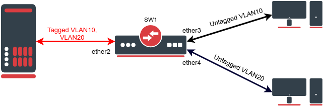
Configuration
...
Below is a list of possible symptoms that might be as a result of this kind of a misconfiguration:
- Cannot change MTU
...
Consider the following scenario, you have multiple devices in your network, most of them are used as a switch/bridge in your network and there are certain endpoints that are supposed to receive and process traffic. To decrease the overhead in your network, you have decided to increase the MTU size so you set a larger MTU size on both endpoints, but you start to notice that some packets are being dropped.
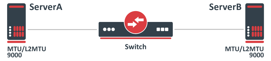
Configuration
...
This is a very simplified problem, but in larger networks, this might not be very easy to detect. For instance, ping might be working since a generic ping packet will be 70 bytes long (14 bytes for Ethernet header, 20 bytes for IPv4 header, 8 bytes for ICMP header, 28 bytes for ICMP payload), but data transfer might not work properly. The reason why some packets might not get forwarded is that MikroTik devices running RouterOS by default has MTU set to 1500 and L2MTU set to something around 1580 bytes (depends on the device), but the Ethernet interface will silently drop anything that does not fit into the L2MTU size. Note that the L2MTU parameter is not relevant to x86 or CHR devices. For a device that is only supposed to forward packets, there is no need to increase the MTU size, it is only required to increase the L2MTU size, RouterOS will not allow you to increase the MTU size that is larger than the L2MTU size. If you require the packet to be received on the interface and the device needs to process this packet rather than just forwarding it, for example, in the case of routing, then it is required to increase the L2MTU and the MTU size, but you can leave the MTU size on the interface to the default value if you are using only IP traffic (that supports packet fragmentation) and don't mind that packets are being fragmented. You can use the ping utility to make sure that all devices are able to forward jumbo frames:
...
Below is a list of possible symptoms that might be as a result of this kind of a misconfiguration:
- Web pages are not able to load up, but ping works properly;
- Tunnels dropping traffic;
- Specific protocols are broken;
- Large packet loss;
Solution
Increase the L2MTU size on your Switch:
...
In case your traffic is encapsulated (VLAN, VPN, MPLS, VPLS, or other), then you might need to consider setting an even a larger L2MTU size. In this scenario, it is not needed to increase the MTU size for the reason described above.
...
Consider the following scenario, you want to transparently bridge two network segments together, either those are tunnel interfaces like EoIP, Wireless interfaces, Ethernet interface, or any other kind of interfaces that can be added to a bridge. Such a setup allows you to seamlessly connect two devices together like there was only a physical cable between them, this is sometimes called a transparent bridge from DeviceA to DeviceB.
...
Below is a list of possible symptoms that might be as a result of this kind of a misconfiguration:
- LLDP neighbors not showing up;
- 802.1x authentication (dot1x) not working;
- LACP interface not passing traffic;
Solution
Since RouterOS v6.43 it is possible to partly disable compliance with IEEE 802.1D and IEEE 802.1Q, this can be done by changing the bridge protocol mode.
...
Consider the following scenario, you have set up multiple Wireless links and to achieve maximum throughput and yet to achieve redundancy you have decided to place Ethernet interfaces into a bond and depending on the traffic that is being forwarded you have chosen a certain bonding mode. This scenario can be applied to any case, where a bonding interface is created between links, that are not directly connected to each other.
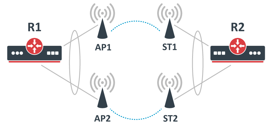
Configuration
...
While the following configuration is relevant to AP1, AP2, ST1, and ST2, where X corresponds to an IP address for each device.
...
While traffic is being forwarded properly between R1 and R2, load balancing, link failover is working properly as well, but devices between R1 and R2 are not always accessible or some of them are completely inaccessible (in most cases AP2 and ST2 are inaccessible). After examining the problem you might notice that packets do not always get forwarded over the required bonding slave and as a result, never is received by the device you are trying to access. This is a network design and bonding protocol limitation. As soon as a packet needs to be sent out through a bonding interface (in this case you might be trying to send ICMP packets to AP2 or ST2), the bonding interface will create a hash based on the selected bonding mode and transmit-hash-policy and will select an interface, through which to send the packet out, regardless if of the destination is only reachable through a certain interface. Some devices will be accessible because the generated hash matches the interface, on which the device is located on, but it might not choose the needed interface as well, which will result in inaccessible device. Only broadcast bonding mode does not have this kind of protocol limitation, but this bonding mode has a very limited use case.
...
Below is a list of possible symptoms that might be as a result of this kind of a misconfiguration:
- Limited connectivity
- Unstable links (in case of balance-rr)
...
Bonding interfaces are not supposed to be connected using in-direct links, but it is still possible to create a workaround. The idea behind this workaround is to find a way to bypass packets being sent out using the bonding interface. There are multiple ways to force a packet not to be sent out using the bonding interface, but essentially the solution is to create new interfaces on top of physical interfaces and add these newly created interfaces to a bond instead of the physical interfaces. One way to achieve this is to create EoIP tunnels on each physical interface, but that creates a huge overhead and will reduce overall throughput. You should create a VLAN interface on top of each physical interface instead, this creates a much smaller overhead and will not impact overall performance noticeably. Here is an example of how R1 and R2 should be reconfigured:
...
| Note |
|---|
LACP (802.3ad) is not mean to be used in setups, where devices bonding slaves are not directly connected, in this case, it is not recommended to use LACP , if there are Wireless links between both routers. LACP requires both bonding slaves to be at the same link speeds, Wireless links can change its their rates at any time, which will decrease overall performance and stability. Other bonding modes should be used instead. |
...
Consider the following scenario, you set up a link between two devices, this can be any link, an Ethernet cable, a wireless link, a tunnel or any other connection. You decide that you want to test the link's bandwidth, but for convenience reasons, you decide to start testing the link with the same devices that are running the link.
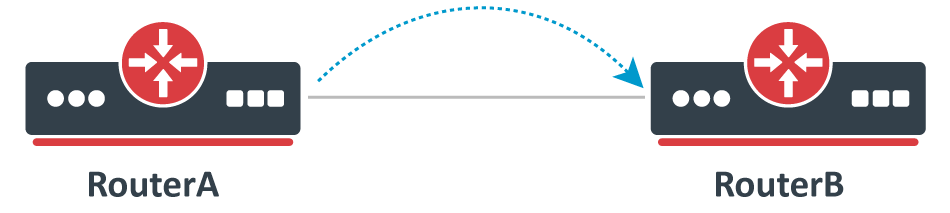
Problem
As soon as you start Bandwidth test or Traffic generator you notice that the throughput is much smaller than expected. For very powerful routers, which should be able to forward many Gigabits per second (Gbps) you notice that only a few Gigabits per second gets forwarded. The reason why this is happening is because of the testing method you are using, you should never test throughput on a router while using the same router for generating traffic because you are adding an additional load on the CPU that reduces the total throughput.
...
Below is a list of possible symptoms that might be as a result of this kind of a misconfiguration:
- Low throughput;
- High CPU usage;
Solution
Use a proper testing method. Don't use Bandwidth-test to test large capacity links and don't run any tool that generates traffic on the same device you are testing. Design your network properly so you can attach devices that will generate and receive traffic on both ends. If you are familiar with Iperf, then this concept should be clear. Remember that in real-world a router or a switch does not generate large amounts of traffic (at least it shouldn't, otherwise, it might indicate an existing security issue), a server/client generates the traffic while a router/switch forwards the traffic (and does some manipulations to the traffic in appropriate cases).
Bridge split-horizon usage
...
After setting the bridge split-horizon on each port, you start to notice that each port is still able to send data between each other. The reason for this is the misuse of bridge split-horizon. A bridge port is only not able to communicate with ports that are in the same horizon, for example, horizon=1 is not able to communicate with horizon=1, but is able to communicate with horizon=2, horizon=3, and so on.
Symptoms
Below is a list of possible symptoms that might be as a result of this kind of a misconfiguration:
- Traffic is being forwarded on different bridge split-horizons
...
As soon as you configure your devices to have connectivity on the ports that are using these SFP optical modules, you might notice that either the link is working properly or experiencing random connectivity issues. There are many vendors that manufacture SFP optical modules, but not all vendors strictly follow SFP MSA, SFF, and IEEE 802.3 standards, which can lead to unpredictable compatibility issues, which is a very common issue when using not well known or unsupported SFP optical modules in MikroTik devices.
...
Below is a list of possible symptoms that might be as a result of this kind of a misconfiguration:
- SFP interface does not link up
- Random packet drop
- Unstable link (flapping)
- SFP module not running after a reboot
- SFP module not running after power-cycle
- SFP module running only on one side
...
You should only use supported SFP modules. Always check the SFP compatibility table if you are intending to use SFP modules manufactured by MikroTik. There are other SFP modules that do work with MikroTik devices as well, check the Supported peripherals table to find other SFP modules that have been confirmed to work with MikroTik devices. Some unsupported modules might not be working properly at certain speeds and with auto-negotiation, you might want to try to disable it and manually set a link speed.