...
- Connect your computer to one of the Ethernet ports;
- Optional - Connect an external antenna to the SMA connector (The antennas are not provided in the package, see "18350121Antenna usage");
- Insert micro SIM card into the slot located under the device;
...
Expansion slots and ports
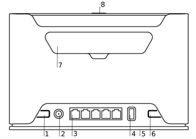
- 18350121Reset button.
- 18350121 Powering DC jack 2.0 mm.
- Five Gigabit ports, supporting automatic cross/straight cable correction (Auto MDI/X). Either straight or crossover cable can be used for connecting to other network devices.
- USB type-A.
- SIM slot for Micro sim card.
- Mode button.
- Cover for external SMA antenna connectors.
- WPS Sync button.
- Integrated Wireless module operating at 2.4 GHz, 802.11b/g/n protocol.
- Integrated Wireless module operating at 5 GHz, 802.11a/n/ac protocol.
...
We recommend checking for updates frequently to receive the latest updates for your RouterOS software to ensure the best performance and stability.
RouterOS includes many configuration options in addition to what is described in this document. We suggest starting here to get yourself accustomed to the possibilities: https://mt.lv/help. In case IP connection is not available, the Winbox tool (https://mt.lv/winbox) can be used to connect to the MAC address of the device from the LAN side (all access is blocked from the Internet port by default).
For recovery purposes, it is possible to boot the device for reinstallation, see section 18350121 Buttons and Jumpers.
Mode button
Mode button located on the back of the unit, to the right side (see "18350121Expansion slots and ports")
The Default configuration for the Mode button is dark mode - to turn off all LEDs. The button can be configured in RouterOS to run any user specified-scripts.
...
| Info |
|---|
Please connect and disconnect the antenna, when the device is turned off! We recommend using our antenna https://mikrotik.com/product/mant_lte_5o |
Removing back cover to access PCB
In case there is a need to access PCB, the back cover can be removed.
- Remove center screw;
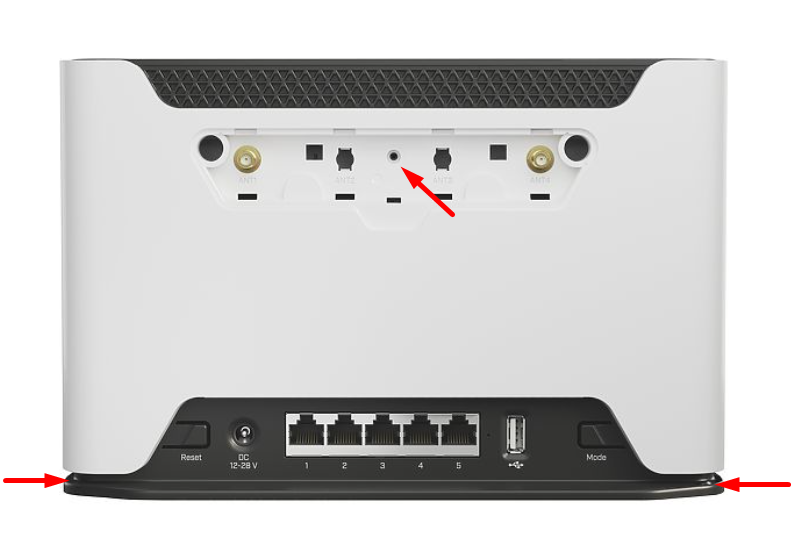
- Use a small screwdriver to pry open backplate in marked spots;
- Continue to pry it open by going up;
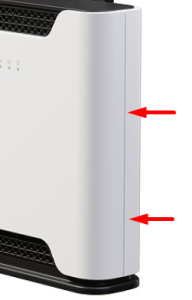
- At the end lift off the whole backplate.
Operating system support
The device supports RouterOS software version v7. The specific factory-installed version number is indicated in the RouterOS menu /system resource. Other operating systems have not been tested.
...