...
Before you work on any equipment, be aware of the hazards involved with electrical circuitry, and be familiar with standard practices for preventing accidents.
Ultimate disposal of this product should be handled according to all national laws and regulations.
All installation methods for mounting an access point on any wall surface is subject to the acceptance of local jurisdiction.
The Installation of the equipment must comply with local and national electrical codes.
This product is intended to be mounted outdoors on a pole but can also be installed indoors. Please read the mounting instructions carefully before beginning installation. Failure to use the correct hardware and configuration or to follow the correct procedures could result in a hazardous situation to for people and damage to the system.
Use only the power supply and accessories approved by the manufacturer, and which can be found in the original packaging of this product.
Read the installation instructions before connecting the system to the power source.
We cannot guarantee that no accidents or damage will occur due to the improper use of the device. Please use this product with care and operate at your own risk!
In the case of device failure, please disconnect it from power. The fastest way to do so is by unplugging the power plug from the power outlet.
It is the customer's responsibility to follow local country regulations, including operation within legal frequency channels, output power, cabling requirements, and Dynamic Frequency Selection (DFS) requirements. All Mikrotik radio devices must be professionally installed.
The equipment is not tested for Outdoor use by UL.
Exposure to Radio Frequency Radiation: This MikroTik equipment complies with the FCC, IC, and European Union radiation exposure limits set forth for an uncontrolled environment. This MikroTik device should be installed and operated no closer than 20 centimeters from your body, occupational user, or the general public.
Connecting
...
- Choose your powering solution (see "Powering").
- Connect your Internet cable to the Ethernet port .
- Set your computer IP configuration to automatic (DHCP).
- Connect your direct input power jack if not using PoE, to start up the device.
- The device will boot up and the Wireless network will be available for connecting.
- Open network connections on your PC, mobile phone, or other device and search for MikroTik wireless network and connect to it.
- (this is optional if using LTE as the primary connection);
- Install your modem using miniPCIe slot (optional);
- Insert the SIM card into the SIM slot;
- Connect the GPS antenna (see "GPS usage", optional);
- Choose your powering solution (see "Powering");
- Navigate to the network connections section on your computer and locate the wireless network named "MikroTik-....". Proceed to connect to it;
Configuration should be made via a wireless network using a web browser or mobile application. Alternatively, you can use the WinBox configuration tool https://mt.lv/winbox;
- Open the httpOnce connected to the wireless network, open https://192.168.88.1
 in your web browser to start configuration, since ;
 - User name: admin, and there is no password by default, you will be logged in automatically. The configuration also can be done using the mobile app (see "MikroTik mobile app"), and WinBox configuration tool https://mt.lv/winbox. (or, for some models, check user and wireless passwords on the sticker);
- Click the "Check for updates" button and update RouterOS to the latest version. The device requires an active internet connection;
- For a manual update of the device, visit the products page at https://mikrotik.com/products to find your product. The required packages are accessible under the "Support&Downloads" menu;
- Upload downloaded packages to the "WinBox Files" menu and reboot the device;
- By upgrading We recommend clicking the "Check for updates" button and updating your RouterOS software to the latest version to ensure the best performance and stability., you can ensure optimal performance, stability, and security updates;
- In the "QuickSet" menu set up the following: Choose your country, to apply country regulation settings, and set ;
- Set up your wireless network password in the left field;
- Set up your router password on the screen that loads.
- Set the Installation to indoors or outdoors, depending on the usage type.
- in the bottom field.
Mounting
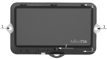
- It is possible to attach the device to a wall, using the provided screw holes on the sides of the unit. The device should be mounted in a way that the cable openings are pointing downward as shown in the picture.
- The ports are protected with a small door, that is held in place with one screw. Use the Philips PH2 screwdriver to access the ports.
- The door has cut-out places for all available ports, but please only break out the openings that you will use. The device can be used both indoors and outdoors. The IP rating scale for this device is IP54.
- The device enclosure has places where you can drill openings for external LTE and GPS antennas. Use a drill to make holes that are appropriate for the antenna cable used.
...
| Warning |
|---|
| When mounting outdoors, please ensure that any cable openings are directed downwards. Use a PoE injector and proper grounding. Recommended using Cat6 cable. Warning! This equipment should be installed and operated with a minimum distance of 20 cm between the device and your body. Operation of this equipment in the residential environment could cause radio interference. Mounting and configuration of this device should be done by a qualified person. |
...
- Direct-input power jack (5.5 mm outside and 2 mm inside, female, pin-positive plug) accepts 8-30 V DC.
- microUSB micro USB port accepts 5 V powering.
- Ethernet port accepts passive and 802.3af/at Power over Ethernet 8-57 V DC (compensate for the loss on cable, so more than 12 V recommended).
...
- Built-in 2 GHz wireless access point module, AP/station/bridge/p2p modes are supported. Onboard PIF antennas built-in. Antenna gain1.5 dBi.
- miniPCIe slot and two SIM slots (can't be used without a modem installed, can't be used both at the same time) to be used with a 3G/4G/LTE modem. Onboard antennas are available, but openings for external antennas are provided on the case.
- Built-in GPS module - uFL connector provided for an external antenna. To enable, set the port to serial0 (this disables the DB9 port on the unit). Supports (GPS, GLONASS, BeiDou, Galileo).
- One 10/100 Ethernet port, supporting automatic cross/straight cable correction (Auto MDI/X). Either straight or crossover cable can be used for connecting to other network devices. The Ethernet port accepts 12-57 V DC powering from a passive PoE injector.
- One DB9 RS232 serial port for serial console access. Configured as 115200 bit/s, 8 data bits, 1 stop bit, no parity. Can't be used if built-in GPS is enabled on serial0.
- One microUSB micro USB 2.0 port for powering only.
...
- Use a wrist grounding strap when unpacking and working with electrical components to avoid electrical discharge (ESD) damage.
- Open the front cover by unscrewing one screw with the Philips PH2 screwdriver.
- Remove four screws on the bottom of the case and lift off the top part of the case. You will see the antenna attached to it.
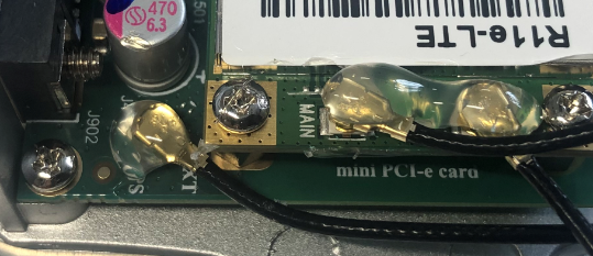
- Locate the miniPCIe card on the PCB and remove two screws.
- Attach provided a thick thermal pad to the card, and install the card into miniPCIe slot so that the thermal pad is between PCB and card.
- The secure card in place using previously removed two screws.
- Attach the grey uFL connector to the MAIN antenna connector of the modem, and attach the black cable to the secondary (or AUX) connector.
- To use external antennas (not included), attach antenna connectors and use a 6.5 mm drill bit to drill holes on the side of the unit. (see "Mounting") description 4.
- Please see the picture bellow below on how to place rubber seals for the best water protection.
...
- Attach antenna connectors to the installed card and GPS connector on the PCB, as additional rubber silicone can be used to secure connectors in place on the card and PCB board.
Attach a thinner thermal pad to the top of the card.
...
Configuration information - https://wikihelp.mikrotik.com/docs/wikidisplay/Manual:System/GPS#Basic_examplesROS/GPS#GPS-Basicexamples
| Warning |
|---|
| The GPS uses an active antenna, connect only when power is turned off. |
...
- Hold this button during boot time until the LED light starts flashing, and release the button to reset the RouterOS configuration (total 5 seconds).
- Keep holding for 5 more seconds, the LED turns solid, release now to turn on CAP mode. The device will now look for a CAPsMAN server (total 10 seconds).
- Or keep holding the button for 5 more seconds until the LED turns off, then release it to make the RouterBOARD look for Netinstall servers (total 15 seconds).
...
For more information about this product, specification, and pictures please visit our web page: {+}https://mikrotik.com/product/ltap_mini_lte_kit+![]()
Operating system support
...
Federal Communication Commission Interference Statement
| Model | FCCID | Contains FCCID |
|---|---|---|
| RB912R-2nD-LTm&R11e-LTE | TV7RB912R-2NDLTM | |
| RB912R-2nD-LTm&R11e-LTE-US | TV7RB912R-2NDLTM | TV7R11ELTE |
| RB912R-2nD-LTm&R11e-4G | TV7RB912R-2NDLTM | TV7R11E4G |
This equipment has been tested and found to comply with the limits for a Class B digital device, pursuant to Part 15 of the FCC Rules. These limits are designed to provide reasonable protection against harmful interference in a residential installation.![]()
...
This equipment complies with the FCC radiation exposure limits set forth for an uncontrolled environment. This equipment should be installed and operated with a minimum distance of 20 cm between the radiator and any part of your body.
Innovation, Science and Economic Development Canada
| Model | IC | Contains IC |
|---|---|---|
| RB912R-2nD-LTm&R11e-LTE | TV7RB912R-2NDLTM | None |
| RB912R-2nD-LTm&R11e-LTE-US | 7442A-912R2NDLTM | 7442A-R11ELTE |
| RB912R-2nD-LTm&R11e-4G | 7442A-912R2NDLTM | 7442A-R11E4G |
This device contains license-exempt transmitter(s)/receiver(s) that comply with Innovation, Science, and Economic Development Canada’s license-exempt RSS(s). Operation is subject to the following two conditions: (1) This device may not cause interference. (2) This device must accept any interference, including interference that may cause undesired operation of the device.
...
UKCA marking

Eurasian Conformity Mark
Частотный диапазон | Мощность передатчика |
|---|---|
2400-2483.5 МГц | ≤100 мВт |
*Доступные частотные каналы могут различаться в зависимости от модели продукта и сертификации.
...
Hereby, Mikrotīkls SIA declares that the radio equipment type RouterBOARD is in compliance with Directive 2014/53/EU. The full text of the EU declaration of conformity is available at the following internet address: https://mikrotik.com/products
WLAN / 2G / 3G / LTE
Operating Frequency / Maximum output power Betriebsfrequenz / maximale Ausgangsleistung Fréquence de fonctionnement / puissance de sortie maximale Frequenza operativa / massima potenza di uscita Frecuencia de funcionamiento / potencia de salida máxima Рабочая частота / максимальная выходная мощность | WLAN | 2400-2483.5 MHz / 20 dBm |
| E-GSM-900 | 900 MHz / 33dB | |
| DCS-1800 | 1800 MHz / 30dB | |
| WCDMA Band I | 1922.4 MHz / 24dB ± 2.7 dB | |
| WCDMA Band VIII | 882.4 MHz / 24dB ± 2.7 dB | |
| LTE Band 1 | 2100 MHz / 23dB ± 2.7 dB | |
| LTE Band 3 | 1700 MHz / 23dB ± 2.7 dB | |
| LTE Band 7 | 2600 MHz / 23dB ± 2.7 dB | |
| LTE Band 8 | 900 MHz / 23dB ± 2.7 dB | |
| LTE Band 20 | 800 MHz / 23dB ± 2.7 dB | |
| LTE Band 38 | 2600 MHz / 23dB ± 2.7 dB | |
| LTE Band 40 | 2300 MHz / 23dB ± 2.7 dB |
| Note |
|---|
This MikroTik device meets Maximum WLAN and LTE transmit power limits per ETSI regulations. For more detailed information see Declaration of Conformity above / Dieses MikroTik-Gerät erfüllt die maximalen WLAN- und LTE-Sendeleistung Grenzwerte gemäß ETSI-Bestimmungen. Weitere Informationen finden Sie oben unter Konformitätserklärung / Cet appareil MikroTik respecte les limites maximales de puissance de transmission WLAN et LTE conformément aux réglementations ETSI. Pour plus d'informations, voir la déclaration de conformité ci-dessus / Questo dispositivo MikroTik è conforme ai limiti massimi di potenza di trasmissione WLAN e LTE in conformità con le normative ETSI. Per ulteriori informazioni, consultare la dichiarazione di conformità sopra / Este dispositivo MikroTik cumple con los límites máximos de potencia de transmisión WLAN y LTE de acuerdo con las regulaciones ETSI. Para obtener más información, consulte la declaración de conformidad anterior / Это устройство MikroTik соответствует максимальным пределам мощности передачи WLAN и LTE в соответствии с правилами ETSI. Для получения дополнительной информации см. Декларацию соответствия выше. |
...