Safety Warnings
Before you work on any equipment, be aware of the hazards involved with electrical circuitry, and be familiar with standard practices for preventing accidents.
Ultimate disposal of this product should be handled according to all national laws and regulations.
All installation methods for mounting an access point on any wall surface is subject to the acceptance of local jurisdiction.
The Installation of the equipment must comply with local and national electrical codes.
This product is intended to be mounted outdoors on a pole. Please read the mounting instructions carefully before beginning installation. Failure to use the correct hardware and configuration or to follow the correct procedures could result in a hazardous situation for people and damage to the system.
Use only the power supply and accessories approved by the manufacturer, and which can be found in the original packaging of this product.
Read the installation instructions before connecting the system to the power source.
We cannot guarantee that no accidents or damage will occur due to the improper use of the device. Please use this product with care and operate at your own risk!
In the case of device failure, please disconnect it from power. The fastest way to do so is by unplugging the power plug from the power outlet.
It is the customer's responsibility to follow local country regulations, including operation within legal frequency channels, output power, cabling requirements, and Dynamic Frequency Selection (DFS) requirements. All Mikrotik radio devices must be professionally installed.
This is a class A device. In a domestic environment, this product might cause radio interference in which case the user might be required to take adequate measures.
Exposure to Radio Frequency Radiation: This MikroTik equipment complies with the FCC, IC, and European Union radiation exposure limits set forth for an uncontrolled environment. This MikroTik device should be installed and operated no closer than 20 centimeters from your body, occupational user, or the general public.
Quickstart
The configuration is the same as PTP Bridge in AP mode, except that wireless mode is set to ap_bridge for PTMP setups. The router can be accessed directly using the address. If the device is connected to the network with enabled DHCP server, configured DHCP client on the bridge interface will get the IP address, that can be used to access the router.
Please follow these quick steps to set up your device:
- Open the upper cover (see "NetMetal ac²#Removing upper and bottom covers");
- Connect an external antenna to the SMA connector (see "NetMetal ac²#Antenna usage");
- Open the bottom cover (see "NetMetal ac²#Removing upper and bottom covers");
- Connect your ISP cable to the device, make sure the ISP is allowing hardware change and will issue an automatic IP address;
- Connect the device to the power source (see "NetMetal ac²#Powering");
- Open network connections on your PC and search for MikroTik wireless network and connect to it;
- The configuration can be done through the wireless network using a Web browser or configuration tool https://mt.lv/winbox;
- Once connected to the wireless network, open WinBox or Web browser;
- The default IP: 192.168.88.1, user name: admin and there is no password (or, for some models, check user and wireless passwords on the sticker);
- Once logged in, use Check For Update button to update the device to the latest software version, the device must have an active Internet connection;
- Once the device is updated, log in again and choose your country on the left side of the screen in the field "Country", to apply country regulation settings;
- Set antenna gain, depending on the antenna you are using, to ensure that EIRP meets the limit set by the local authorities;
- Choose the security type WPA/WPA2 and insert a wireless password;
- Set a password for your device, it will be used to login next time and click Apply Configuration.
Powering
The device accepts power in the following ways:
- Ethernet port accepts PoE 802.3af/at 24-57 V DC ⎓;
- Direct-input power jack (5.5 mm outside and 2 mm inside, female, pin positive plug) accepts 12-57 V DC⎓.
Connecting to a PoE Adapter:
- Connect the Ethernet cable from the device to the PoE+DATA port of the PoE adapter;
- Connect an Ethernet cable from your local network (LAN) to the PoE adapter;
- Connect the power cord to the adapter, and then plug the power cord into a power outlet.
MikroTik mobile app
Use the MikroTik smartphone app to configure your router in the field, or to apply the most basic initial settings for your MikroTik home access point.

- Scan QR code and choose your preferred OS.
- Install and open application.
- By default, the IP address and user name will be already entered.
- Click Connect to establish a connection to your device through a wireless network.
- Choose Quick setup and application will guide you through all basic configuration settings in a couple of easy steps.
- An advanced menu is available to fully configure all necessary settings.
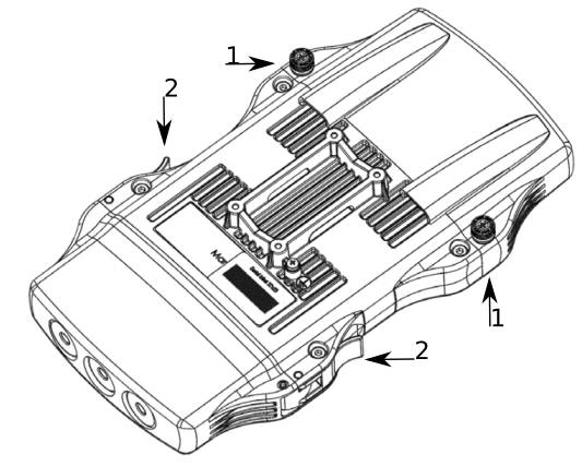
Removing upper and bottom covers
- To remove the upper cover, unscrew two captive screws and slide it off the main body. Do not remove screws completely, when assembling tightening torque 0.2 Nm.
- To remove the bottom cover, release clips for both fasteners and cover will be free to open.
Mounting
The NetMetal ac2 is designed to be used outdoors and mounted on pole or DIN rail.
When mounting, please ensure that cable feed is pointing downwards.
The IP rating scale of this device is IP66. We recommend using Cat6 shielded cables.
Warning! This equipment should be installed and operated with a minimum distance of 20 cm between the device and your body. Operation of this equipment in the residential environment could cause radio interference.
Mounting and configuration of this device should be done by a qualified person.
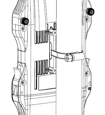
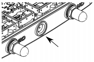
The mounting hose clamp is provided with the package.
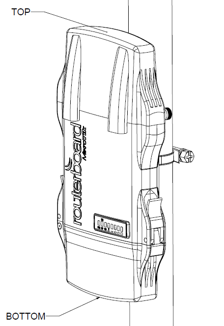
- Guide hose clamp through the opening on the back of the device.
- Attach to the pole or mast.
- Align and secure by hose clamp screw using PH2 screwdriver.
- The device should be always placed by TOP cover facing upwards.
- When mounting on DIN rail, please find a special bracket in the package and secure it with four screws to the back of the unit.
- With the attached mounting bracket you will be able to slide the device on the DIN rail.
Grounding
The installation infrastructure (towers and masts), as well as the router itself, must be properly grounded. The device includes a grounding wire attachment screw. Attach your grounding wire to the grounding screw, then attach the other end of the grounding wire to the grounded mast.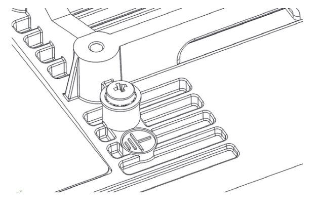
Please secure all loose Ethernet cables and antenna cables to the pole or mast approximately 30cm from the device, so that the cable weight is not pulling the ports and connectors.
Front status LED behavior
RouterOS allows configuring each LED's activity the way that the user wishes. It is possible to configure the LEDs to display wireless strength, blink the LEDs on interface traffic activity and many other options. For further information please visit https://wiki.mikrotik.com/wiki/Manual:System/LEDS
Default factory configuration for this device:
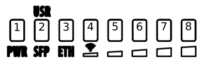
- Solid Blue – The device is powered on.
- Solid Green – Active SFP port.
- Solid Green – Active Ethernet port.
- - 8. Solid Green – The set of five green LEDs, shows the signal strength.
Configuration
The device is configured as a wireless access point, with the Ethernet port configured as a DHCP client, for connecting to your ISP router or switch. A DHCP server is configured on the wireless interface.
We recommend clicking the "Check for updates" button in the QuickSet menu, as updating your RouterOS software to the latest version ensures the best performance and stability. For wireless models, please make sure you have selected the country where the device will be used, to conform with local regulations.
RouterOS includes many configuration options in addition to what is described in this document. We suggest starting here to get yourself accustomed to the possibilities: https://mt.lv/help. In case IP connection is not available, the Winbox tool (https://mt.lv/winbox) can be used to connect to the MAC address of the device from the LAN side (all access is blocked from the Internet port by default).
For recovery purposes, it is possible to boot the device for reinstallation, see a section Reset button.
Expansion slots and ports
- Gigabit Ethernet port, supporting automatic cross/straight cable correction (Auto MDI/X). Either straight or crossover cable can be used for connecting to other network devices.
- SFP port.
- External SMA antenna connectors.
- MiniPCIe slot.
- Integrated Wireless module operating at 2.4 GHz, 802.11b/g/n protocol.
- Integrated Wireless module operating at 5 GHz, 802.11a/n/ac protocol.
- USB type-A.
Reset button
The reset button has three functions:
- Hold this button during boot time until LED light starts flashing, release the button to reset RouterOS configuration (total 5 seconds).
- Keep holding for 5 more seconds, LED turns solid, release now to turn on CAP mode. The device will now look for a CAPsMAN server (total 10 seconds).
- Or Keep holding the button for 5 more seconds until LED turns off, then release it to make the RouterBOARD look for Netinstall servers (total 15 seconds).
Regardless of the above option used, the system will load the backup RouterBOOT loader if the button is pressed before power is applied to the device. Useful for RouterBOOT debugging and recovery.
Accessories
Package includes the following accessories that come with the device:
- EU Switching Power Supply 48 V ⎓ 0.95 A 45.6 W.
- Gigabit POE injector.
- K-27 DIN rail bracket mounting set.
- Hose clamp 40/60 w2 A2 9 mm.
Please visit wiki pages for MikroTik SFP module compatibility table: https://wiki.mikrotik.com/wiki/MikroTik_SFP_module_compatibility_table
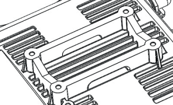
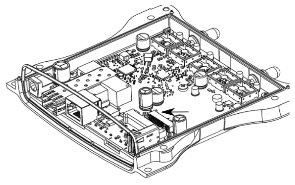
MiniPCIe slot usage
This NetMetal version is without modem installed. To install the module you will need to remove the upper cover and open bottom cover (see "NetMetal ac²#Removing upper and bottom covers"). Installing a miniPCIe module should be done by a qualified person, please follow safety precautions when handling electrical equipment:
- Use a wrist grounding strap when unpacking and working with electrical components to avoid electrical discharge (ESD) damage.
- Removing four screws using the PH2 screwdriver.
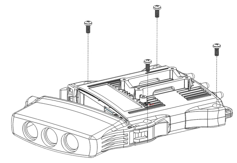
- Remove the top cover by lifting it.
- Locate the miniPCIe slot on the PCB and remove two factory attached screws.
- Attach provided a thick thermal pad to the card, and install the card into miniPCIe slot so that the thermal pad is between PCB and card.
- The secure card in place using previously removed two screws.
- Attach the grey uFL connector to the MAIN antenna connector of the modem, attach the black cable to the secondary (or AUX) connector.
- Attach a thinner thermal pad to the top of the card.
- Drill a hole for cables using a 6.5 mm drill to provide an opening for card antenna cables.
- Guide through the card cables.
- Reassemble.
When assembling make sure the rubber sealing is placed firmly around the case for equal spread to prevent water contamination. Case screw torque 2,5 Nm.
When mounting the antenna for the installed card, please make sure to keep them separate at a good distance from Wireless antennas.
Antenna usage
Antenna Installation. WARNING: It is the installer's responsibility to ensure that when using the authorized antennas in the United States (or where FCC rules apply); only those antennas certified with the product are used. The use of any antenna other than those certified with the product is expressly forbidden in accordance with FCC rules CFR47 part 15.204. The installer should configure the output power level of antennas, according to country regulations and per antenna type. Professional installation is required for equipment with connectors to ensure compliance with health and safety issues.
LIST OF APPROVED 2GHz ANTENNAS:
- 5 dBi Dipole ACOMNIRPSMA
LIST OF APPROVED 5GHz ANTENNAS:
- 30 dBi Parabolic dish MTAD-5G-30D3
- 19 dBi Sector MTAS-5G-19D120
Antennas of the same type and lower gain than those listed above may be used in compliance with certification.
More information on the wireless interface: https://wiki.mikrotik.com/wiki/Manual:Interface/Wireless
Specifications
For more information about this product, specifications, pictures, downloads and test results please visit our web page: https://mikrotik.com/product/NetMetal_ac2
Operating system support
The device supports RouterOS software version 6. The specific factory-installed version number is indicated in the RouterOS menu /system resource. Other operating systems have not been tested.
| Note |
|---|
To avoid pollution of the environment, please separate the device from household waste and dispose of it in a safe manner, such as in designated waste disposal sites. Familiarize yourself with the procedures for the proper transportation of the equipment to the designated disposal sites in your area. |
Federal Communication Commission Interference Statement
FCC ID: TV7RB922-5HPACT, TV7RB921-5SHPACT, TV7A21GS-5HPACD.
This equipment has been tested and found to comply with the limits for a Class A digital device, pursuant to Part 15 of the FCC Rules. These limits are designed to provide reasonable protection against harmful interference in a commercial installation.
This equipment generates, uses, and can radiate radio frequency energy and, if not installed and used in accordance with the instruction manual, may cause harmful interference to radio communications. Operation of this equipment in a residential area is likely to cause harmful interference in which case the user will be required to correct the interference at his own expense.
FCC Caution: Any changes or modifications not expressly approved by the party responsible for compliance could void the user's authority to operate this equipment.
This device complies with Part 15 of the FCC Rules. Operation is subject to the following two conditions: (1) This device may not cause harmful interference, and (2) this device must accept any interference received, including interference that may cause undesired operation.
This device and its antenna must not be co-located or operation in conjunction with any other antenna or transmitter.
IMPORTANT: Exposure to Radio Frequency Radiation.
This equipment complies with the FCC RF radiation exposure limits set forth for an uncontrolled environment. This equipment should be installed and operated with a minimum distance of 20cm between the radiator and any part of your body.
Antenna Installation. WARNING: It is the installer's responsibility to ensure that when using the authorized antennas in the United States (or where FCC rules apply); only those antennas certified with the product are used. The use of any antenna other than those certified with the product is expressly forbidden in accordance to FCC rules CFR47 part 15.204. The installer should configure the output power level of antennas, according to country regulations and per antenna type. Professional installation is required for equipment with connectors to ensure compliance with health and safety issues.
LIST OF APPROVED 2GHz ANTENNAS:
• 24 dBi Dish DC 24-HD-PFIP
• 20 dBi Panel WLP-2450-20
• 17 dBi Sector SA 24-90-17-WB
• 15 dBi Omni Directional (pole) WL0-2450-15
• 13 dBi Omni Directional (hor. Polarization) HP, 0DH 24-13
LIST OF APPROVED 5GHz ANTENNAS:
• 8.5 dBi Omni MTI Wireless MT-482016NA
• 24 dBi Panel Pacific Wireless PA58-24
• 32 dBi Dish Pacific Wireless HDDA5W-32-DP
Antennas of the same type and lower gain than those listed above may be used in compliance with certification.
Innovation, Science and Economic Development Canada
IC: 7442A-D2352AC
This device complies with Industry Canada's license-exempt RSS standard(s). Operation is subject to the following two conditions: (1) this device may not cause interference, and (2) this device must accept any interference, including interference that may cause undesired operation of the device.
Le présent appareil est conforme aux CNR d'Industrie Canada applicables aux appareils radio exempts de licence. L'exploitation est autorisée aux deux conditions suivantes: (1) l'appareil ne doit pas produire de brouillage, et (2) l'utilisateur de l'appareil doit accepter tout brouillage radioélectrique subi, même si le brouillage est susceptible d'en compromettre le fonctionnement.
This Class A digital apparatus complies with Canadian ICES-003.
Cet appareil numérique de la classe [A] est conforme à la norme NMB-003 du Canada.
CAN ICES-003 (A) / NMB-003 (A)
The device for operation in the band 5150–5250 MHz is only for indoor use to reduce the potential for harmful interference to co-channel mobile satellite systems.
Les dispositifs fonctionnant dans la bande de 5 150 à 5 250 MHz sont réservés uniquement pour une utilisation à l'intérieur afin de réduire les risques de brouillage préjudiciable aux systèmes de satellites mobiles utilisant les mêmes canaux
IMPORTANT: Exposure to Radio Frequency Radiation.
This equipment complies with the FCC RF radiation exposure limits set forth for an uncontrolled environment. This equipment should be installed and operated with a minimum distance of 20 cm between the radiator and any part of your body.
UKCA marking

Eurasian Conformity Mark
Частотный диапазон | Мощность передатчика |
|---|---|
5150-5350 МГц, 5650-5850 МГц | ≤100 мВт |
*Доступные частотные каналы могут различаться в зависимости от модели продукта и сертификации.
Информация о дате изготовления устройства указана в конце серийного номера на его наклейке через дробь. Первая цифра означает номер года (последняя цифра года), две последующие означают номер недели.
Изготовитель: Mikrotikls SIA, Aizkraukles iela 23, Riga, LV-1006, Латвия, support@mikrotik.com. Сделано в Китае, Латвии или Литве. Cм. на упаковке.
Для получения подробных сведений о гарантийном обслуживании обратитесь к продавцу. Информация об импортерах продукции MikroTik в Российскую Федерацию: https://mikrotik.com/buy/europe/russia
Продукты MikroTik, которые поставляются в Евразийский таможенный союз, оцениваются с учетом соответствующих требований и помечены знаком EAC, как показано ниже:

Norma Oficial Mexicana
Rango de frecuencia (potencia de salida máxima): 5725-5850 MHz (30 dBm). Los canales de frecuencia disponibles pueden variar según el modelo y la certificación del producto.
EFICIENCIA ENERGETICA CUMPLE CON LA NOM-029-ENER-2017.
La operacion de este equipo esta sujeta a las siguientes dos condiciones:
- Es posible que este equipo o dispositivo no cause interferencia perjudicial y.
- Este equipo debe aceptar cualquier interferencia, incluyendo la que pueda causar su operacion no deseada.
Fabricante: Mikrotikls SIA, Brivibas gatve 214i, Riga, LV-1039, Latvia.
País De Origen: Letonia; Lituania; China (Republica Popular); Estados Unidos De America; Mexico.
Por favor contacte a su distribuidor local para preguntas regionales específicas. La lista de importadores se puede encontrar en nuestra página de inicio – https://mikrotik.com/buy/latinamerica/mexico.
The National Commission for the State Regulation of Communications and Informatization by Ukraine
Виробник: Mikrotikls SIA, Brivibas gatve 214i Рига, Латвія, LV1039.
Робоча частота (Максимальна вихідна потужність): 5150-5250 МГц (23 дБм), 5250-5350 МГц (20 дБм), 5470-5725 МГц (27 дБм).
| Note |
|---|
Справжнім Mikrotikls SIA заявляє, що маршрутизатор відповідає основним вимогам та іншим відповідним положенням директиви 2014/53/EC, а також суттєвим вимогам Технічного регламенту радіообладнання, затвердженого постановою Кабінету Міністрів України від 24 травня 2017 року № 355. Для експлуатації в Україні необхідно отримати дозвіл на експлуатацію у порядку, затвердженому рішенням НКРЗІ від 01.11.2012 № 559, зареєстрованому в Міністерстві юстиції України 03.01.2013 за № 57/22589. |
CE Declaration of Conformity
Manufacturer: Mikrotikls SIA, Brivibas gatve 214i Riga, Latvia, LV1039.
Hereby, Mikrotīkls SIA declares that the radio equipment type RouterBOARD is in compliance with Directive 2014/53/EU. The full text of the EU declaration of conformity is available at the following internet address: https://mikrotik.com/products![]()
Frequency bands terms of use
Frequency range (for applicable models) | Channels used | Maximum Output Power (EIRP) | Restriction |
2412-2472 MHz | 1 - 13 | 20 dBm | Without any restriction to use in all EU Member States |
5150-5250 MHz | 26 - 48 | 23 dBm | Restricted to indoor use only* |
5250-5350 MHz | 52 - 64 | 20 dBm | Restricted to indoor use only* |
5470-5725 MHz | 100 - 140 | 27 dBm | Without any restriction to use in all EU Member States |
* It is the customer's responsibility to follow local country regulations, including operation within legal frequency channels, output power, cabling requirements, and Dynamic Frequency Selection (DFS) requirements. All Mikrotik radio devices must be professionally installed!
| Note |
|---|
This MikroTik device meets Maximum WLAN transmit power limits per ETSI regulations. For more detailed information see Declaration of Conformity above / Dieses MikroTik-Gerät erfüllt die maximalen WLAN- Sendeleistung Grenzwerte gemäß ETSI-Bestimmungen. Weitere Informationen finden Sie oben unter Konformitätserklärung / Cet appareil MikroTik respecte les limites maximales de puissance de transmission WLAN conformément aux réglementations ETSI. Pour plus d'informations, voir la déclaration de conformité ci-dessus / Questo dispositivo MikroTik è conforme ai limiti massimi di potenza di trasmissione WLAN in conformità con le normative ETSI. Per ulteriori informazioni, consultare la dichiarazione di conformità sopra / Este dispositivo MikroTik cumple con los límites máximos de potencia de transmisión WLAN de acuerdo con las regulaciones ETSI. Para obtener más información, consulte la declaración de conformidad anterior / Это устройство MikroTik соответствует максимальным пределам мощности передачи WLAN в соответствии с правилами ETSI. Для получения дополнительной информации см. Декларацию соответствия выше.
The WLAN function for this device is restricted to indoor use only when operating in the 5150 to 5350 MHz frequency range. / Die WLAN-Funktion dieses Geräts ist nur für die Verwendung in Innenräumen im Frequenzbereich 5150 bis 5350 MHz beschränkt. / La fonction WLAN de cet appareil est limitée à une utilisation en intérieur uniquement lorsqu'il fonctionne dans la gamme de fréquences 5150 à 5350 MHz. / La funzione WLAN per questo dispositivo è limitata all'uso interno solo quando si opera nella gamma di frequenza da 5150 a 5350 MHz. / La función WLAN para este dispositivo está restringida al uso en interiores solo cuando se opera en el rango de frecuencia de 5150 a 5350 MHz. / Функция WLAN для этого устройства ограничена использованием внутри помещения только при работе в диапазоне частот от 5150 до 5350 МГц. |

| Info |
|---|
| Note. The information contained here is subject to change. Please visit the product page on www.mikrotik.com for the most up to date version of this document. |
Quickstart
The configuration is the same as PTP Bridge in AP mode, except that wireless mode is set to ap_bridge for PTMP setups. The router can be accessed directly using the address. If the device is connected to the network with enabled DHCP server, configured DHCP client on the bridge interface will get the IP address, that can be used to access the router.
Please follow these quick steps to set up your device:
- Open the upper cover (see "NetMetal ac²#Removing upper and bottom covers");
- Connect an external antenna to the SMA connector (see "NetMetal ac²#Antenna usage");
- Open the bottom cover (see "NetMetal ac²#Removing upper and bottom covers");
- Connect your ISP cable to the device, make sure the ISP is allowing hardware change and will issue an automatic IP address;
- Connect the device to the power source (see "NetMetal ac²#Powering");
- Open network connections on your PC and search for MikroTik wireless network and connect to it;
- The configuration can be done through the wireless network using a Web browser or configuration tool https://mt.lv/winbox;
- Once connected to the wireless network, open WinBox or Web browser;
- The default IP: 192.168.88.1, user name: admin and there is no password;
- Once logged in, use Check For Update button to update the device to the latest software version, the device must have an active Internet connection;
- Once the device is updated, log in again and choose your country on the left side of the screen in the field "Country", to apply country regulation settings;
- Set antenna gain, depending on the antenna you are using, to ensure that EIRP meets the limit set by the local authorities;
- Choose the security type WPA/WPA2 and insert a wireless password;
- Set a password for your device, it will be used to login next time and click Apply Configuration.
Powering
The device accepts power in the following ways:
- Ethernet port accepts PoE 802.3af/at 24-57 V DC ⎓;
- Direct-input power jack (5.5 mm outside and 2 mm inside, female, pin positive plug) accepts 12-57 V DC⎓.
Connecting to a PoE Adapter:
- Connect the Ethernet cable from the device to the PoE+DATA port of the PoE adapter;
- Connect an Ethernet cable from your local network (LAN) to the PoE adapter;
- Connect the power cord to the adapter, and then plug the power cord into a power outlet.
MikroTik mobile app
Use the MikroTik smartphone app to configure your router in the field, or to apply the most basic initial settings for your MikroTik home access point.
- Scan QR code and choose your preferred OS.
- Install and open application.
- By default, the IP address and user name will be already entered.
- Click Connect to establish a connection to your device through a wireless network.
- Choose Quick setup and application will guide you through all basic configuration settings in a couple of easy steps.
- An advanced menu is available to fully configure all necessary settings.
Removing upper and bottom covers
- To remove the upper cover, unscrew two captive screws and slide it off the main body. Do not remove screws completely, when assembling tightening torque 0.2 Nm.
- To remove the bottom cover, release clips for both fasteners and cover will be free to open.
Mounting
...
When mounting, please ensure that cable feed is pointing downwards.
The IP rating scale of this device is IP66. We recommend using Cat6 shielded cables.
Warning! This equipment should be installed and operated with a minimum distance of 20 cm between the device and your body. Operation of this equipment in the residential environment could cause radio interference.
Mounting and configuration of this device should be done by a qualified person.
The mounting hose clamp is provided with the package.
- Guide hose clamp through the opening on the back of the device.
- Attach to the pole or mast.
- Align and secure by hose clamp screw using PH2 screwdriver.
- The device should be always placed by TOP cover facing upwards.
- When mounting on DIN rail, please find a special bracket in the package and secure it with four screws to the back of the unit.
- With the attached mounting bracket you will be able to slide the device on the DIN rail.
Grounding
The installation infrastructure (towers and masts), as well as the router itself, must be properly grounded. The device includes a grounding wire attachment screw. Attach your grounding wire to the grounding screw, then attach the other end of the grounding wire to the grounded mast.
Please secure all loose Ethernet cables and antenna cables to the pole or mast approximately 30cm from the device, so that the cable weight is not pulling the ports and connectors.
Front status LED behavior
RouterOS allows configuring each LED's activity the way that the user wishes. It is possible to configure the LEDs to display wireless strength, blink the LEDs on interface traffic activity and many other options. For further information please visit https://wiki.mikrotik.com/wiki/Manual:System/LEDS
Default factory configuration for this device:
- Solid Blue – The device is powered on.
- Solid Green – Active SFP port.
- Solid Green – Active Ethernet port.
- - 8. Solid Green – The set of five green LEDs, shows the signal strength.
Configuration
The device is configured as a wireless access point, with the Ethernet port configured as a DHCP client, for connecting to your ISP router or switch. A DHCP server is configured on the wireless interface.
We recommend clicking the "Check for updates" button in the QuickSet menu, as updating your RouterOS software to the latest version ensures the best performance and stability. For wireless models, please make sure you have selected the country where the device will be used, to conform with local regulations.
RouterOS includes many configuration options in addition to what is described in this document. We suggest starting here to get yourself accustomed to the possibilities: https://mt.lv/help. In case IP connection is not available, the Winbox tool (https://mt.lv/winbox) can be used to connect to the MAC address of the device from the LAN side (all access is blocked from the Internet port by default).
For recovery purposes, it is possible to boot the device for reinstallation, see a section Reset button.
Expansion slots and ports
- Gigabit Ethernet port, supporting automatic cross/straight cable correction (Auto MDI/X). Either straight or crossover cable can be used for connecting to other network devices.
- SFP port.
- External SMA antenna connectors.
- MiniPCIe slot.
- Integrated Wireless module operating at 2.4 GHz, 802.11b/g/n protocol.
- Integrated Wireless module operating at 5 GHz, 802.11a/n/ac protocol.
- USB type-A.
Reset button
The reset button has three functions:
- Hold this button during boot time until LED light starts flashing, release the button to reset RouterOS configuration (total 5 seconds).
- Keep holding for 5 more seconds, LED turns solid, release now to turn on CAP mode. The device will now look for a CAPsMAN server (total 10 seconds).
- Or Keep holding the button for 5 more seconds until LED turns off, then release it to make the RouterBOARD look for Netinstall servers (total 15 seconds).
Regardless of the above option used, the system will load the backup RouterBOOT loader if the button is pressed before power is applied to the device. Useful for RouterBOOT debugging and recovery.
Accessories
Package includes the following accessories that come with the device:
- EU Switching Power Supply 48 V ⎓ 0.95 A 45.6 W.
- Gigabit POE injector.
- K-27 DIN rail bracket mounting set.
- Hose clamp 40/60 w2 A2 9 mm.
...
MiniPCIe slot usage
This NetMetal version is without modem installed. To install the module you will need to remove the upper cover and open bottom cover (see "NetMetal ac²#Removing upper and bottom covers"). Installing a miniPCIe module should be done by a qualified person, please follow safety precautions when handling electrical equipment:
- Use a wrist grounding strap when unpacking and working with electrical components to avoid electrical discharge (ESD) damage.
- Removing four screws using the PH2 screwdriver.
- Remove the top cover by lifting it.
- Locate the miniPCIe slot on the PCB and remove two factory attached screws.
- Attach provided a thick thermal pad to the card, and install the card into miniPCIe slot so that the thermal pad is between PCB and card.
- The secure card in place using previously removed two screws.
- Attach the grey uFL connector to the MAIN antenna connector of the modem, attach the black cable to the secondary (or AUX) connector.
- Attach a thinner thermal pad to the top of the card.
- Drill a hole for cables using a 6.5 mm drill to provide an opening for card antenna cables.
- Guide through the card cables.
- Reassemble.
...
Antenna usage
Antenna Installation. WARNING: It is the installer's responsibility to ensure that when using the authorized antennas in the United States (or where FCC rules apply); only those antennas certified with the product are used. The use of any antenna other than those certified with the product is expressly forbidden in accordance with FCC rules CFR47 part 15.204. The installer should configure the output power level of antennas, according to country regulations and per antenna type. Professional installation is required for equipment with connectors to ensure compliance with health and safety issues.
LIST OF APPROVED 2GHz ANTENNAS:
- 5 dBi Dipole ACOMNIRPSMA
LIST OF APPROVED 5GHz ANTENNAS:
- 30 dBi Parabolic dish MTAD-5G-30D3
- 19 dBi Sector MTAS-5G-19D120
Antennas of the same type and lower gain than those listed above may be used in compliance with certification.
More information on the wireless interface: https://wiki.mikrotik.com/wiki/Manual:Interface/Wireless
Specifications
For more information about this product, specifications, pictures, downloads and test results please visit our web page: https://mikrotik.com/product/NetMetal_ac2
Operating system support
The device supports RouterOS software version 6. The specific factory-installed version number is indicated in the RouterOS menu /system resource. Other operating systems have not been tested.
Safety Warnings
Before you work on any equipment, be aware of the hazards involved with electrical circuitry and be familiar with standard practices for preventing accidents.
Ultimate disposal of this product should be handled according to all national laws and regulations.
The Installation of the equipment must comply with local and national electrical codes.
This unit is intended to be mounted on a pole. Please read the wall mounting instructions carefully before beginning installation. Failure to use the correct hardware or to follow the correct procedures could result in a hazardous situation to people and damage to the system.
Read the installation instructions before connecting the system to the power source.
It is the customer's responsibility to follow local country regulations, including operation within legal frequency channels, output power, cabling requirements, and Dynamic Frequency Selection (DFS) requirements. All Mikrotik radio devices must be professionally installed.
Federal Communication Commission Interference Statement
FCC ID: TV7RB922-5HPACT, TV7RB921-5SHPACT, TV7A21GS-5HPACD. This equipment has been tested and found to comply with the limits for a Class B digital device, pursuant to Part 15 of the FCC Rules. These limits are designed to provide reasonable protection against harmful interference in a residential installation.
This equipment generates, uses and can radiate radio frequency energy and, if not installed and used in accordance with the instructions, may cause harmful interference to radio communications. However, there is no guarantee that interference will not occur in a particular installation. If this equipment does cause harmful interference to radio or television reception, which can be determined by turning the equipment off and on, the user is encouraged to try to correct the interference by one of the following measures:
- Reorient or relocate the receiving antenna.
- Increase the separation between the equipment and receiver.
- Connect the equipment into an outlet on a circuit different from that to which the receiver is connected.
- Consult the dealer or an experienced radio/TV technician for help.
FCC Caution: Any changes or modifications not expressly approved by the party responsible for compliance could void the user's authority to operate this equipment.
This device complies with Part 15 of the FCC Rules. Operation is subject to the following two conditions: (1) This device may not cause harmful interference, and (2) this device must accept any interference received, including interference that may cause undesired operation.
This device and its antenna must not be co-located or operation in conjunction with any other antenna or transmitter.
IMPORTANT: Exposure to Radio Frequency Radiation. This equipment complies with the FCC RF radiation exposure limits set forth for an uncontrolled environment. This equipment should be installed and operated with a minimum distance of 20cm between the radiator and any part of your body.
Antenna Installation. WARNING: It is the installer's responsibility to ensure that when using the authorized antennas in the United States (or where FCC rules apply); only those antennas certified with the product are used. The use of any antenna other than those certified with the product is expressly forbidden in accordance to FCC rules CFR47 part 15.204. The installer should configure the output power level of antennas, according to country regulations and per antenna type. Professional installation is required for equipment with connectors to ensure compliance with health and safety issues.
LIST OF APPROVED 2GHz ANTENNAS:
• 24 dBi Dish DC 24-HD-PFIP
• 20 dBi Panel WLP-2450-20
• 17 dBi Sector SA 24-90-17-WB
• 15 dBi Omni Directional (pole) WL0-2450-15
• 13 dBi Omni Directional (hor. Polarization) HP, 0DH 24-13
LIST OF APPROVED 5GHz ANTENNAS:
• 8.5 dBi Omni MTI Wireless MT-482016NA
• 24 dBi Panel Pacific Wireless PA58-24
• 32 dBi Dish Pacific Wireless HDDA5W-32-DP
Antennas of the same type and lower gain than those listed above may be used in compliance with certification.
CE Declaration of Conformity
Manufacturer: Mikrotikls SIA, Brivibas gatve 214i Riga, Latvia, LV1039.
...
BG
...
С настоящото Mikrotīkls SIA декларира, че този тип радиосъоръжение RouterBOARD е в съответствие с Директива 2014/53/ЕС. Цялостният текст на ЕС декларацията за съответствие може да се намери на следния интернет адрес:
https://mikrotik.com/products...
CS
...
Tímto Mikrotīkls SIA prohlašuje, že typ rádiového zařízení RouterBOARD je v souladu se směrnicí 2014/53/EU. Úplné znění EU prohlášení o shodě je k dispozici na této internetové adrese:
https://mikrotik.com/products...
DA
...
Hermed erklærer Mikrotīkls SIA , at radioudstyrstypen RouterBOARD er i overensstemmelse med direktiv 2014/53/EU. EU-overensstemmelseserklæringens fulde tekst kan findes på følgende internetadresse:
https://mikrotik.com/products...
DE
...
Hiermit erklärt Mikrotīkls SIA , dass der Funkanlagentyp RouterBOARD der Richtlinie 2014/53/EU entspricht. Der vollständige Text der EU-Konformitätserklärung ist unter der folgenden Internetadresse verfügbar:
https://mikrotik.com/products...
EL
...
Με την παρούσα ο/η Mikrotīkls SIA , δηλώνει ότι ο ραδιοεξοπλισμός RouterBOARD πληροί την οδηγία 2014/53/ΕΕ. Το πλήρες κείμενο της δήλωσης συμμόρφωσης ΕΕ διατίθεται στην ακόλουθη ιστοσελίδα στο διαδίκτυο:
https://mikrotik.com/products...
EN
...
Hereby, Mikrotīkls SIA declares that the radio equipment type RouterBOARD is in compliance with Directive 2014/53/EU. The full text of the EU declaration of conformity is available at the following internet address:
https://mikrotik.com/products...
ES
...
Por la presente, Mikrotīkls SIA declara que el tipo de equipo radioeléctrico RouterBOARD es conforme con la Directiva 2014/53/UE. El texto completo de la declaración UE de conformidad está disponible en la dirección Internet siguiente:
https://mikrotik.com/products...
ET
...
Käesolevaga deklareerib Mikrotīkls SIA , et käesolev raadioseadme tüüp RouterBOARD vastab direktiivi 2014/53/EL nõuetele. ELi vastavusdeklaratsiooni täielik tekst on kättesaadav järgmisel internetiaadressil:
https://mikrotik.com/products...
FI
...
Mikrotīkls SIA vakuuttaa, että radiolaitetyyppi RouterBOARD on direktiivin 2014/53/EU mukainen. EU-vaatimustenmukaisuusvakuutuksen täysimittainen teksti on saatavilla seuraavassa internetosoitteessa:
https://mikrotik.com/products...
FR
...
Le soussigné, Mikrotīkls SIA , déclare que l'équipement radioélectrique du type RouterBOARD est conforme à la directive 2014/53/UE. Le texte complet de la déclaration UE de conformité est disponible à l'adresse internet suivante:
https://mikrotik.com/products...
HR
...
Mikrotīkls SIA ovime izjavljuje da je radijska oprema tipa RouterBOARD u skladu s Direktivom 2014/53/EU. Cjeloviti tekst EU izjave o sukladnosti dostupan je na sljedećoj internetskoj adresi:
https://mikrotik.com/products...
HU
...
Mikrotīkls SIA igazolja, hogy a RouterBOARD típusú rádióberendezés megfelel a 2014/53/EU irányelvnek. Az EU-megfelelőségi nyilatkozat teljes szövege elérhető a következő internetes címen:
https://mikrotik.com/products...
IT
...
Il fabbricante, Mikrotīkls SIA , dichiara che il tipo di apparecchiatura radio RouterBOARD è conforme alla direttiva 2014/53/UE. Il testo completo della dichiarazione di conformità UE è disponibile al seguente indirizzo Internet:
https://mikrotik.com/products...
IS
...
Hér með lýsir Mikrotīkls SIA yfir því að RouterBOARD er í samræmi við grunnkröfur og aðrar kröfur, sem gerðar eru í tilskipun 2014/53/EU. Fullur texti ESB samræmisyfirlýsing er að finna á eftirfarandi netfangi:
https://mikrotik.com/products...
LT
...
Aš, Mikrotīkls SIA , patvirtinu, kad radijo įrenginių tipas RouterBOARD atitinka Direktyvą 2014/53/ES. Visas ES atitikties deklaracijos tekstas prieinamas šiuo interneto adresu:
https://mikrotik.com/products...
LV
...
Ar šo Mikrotīkls SIA deklarē, ka radioiekārta RouterBOARD atbilst Direktīvai 2014/53/ES. Pilns ES atbilstības deklarācijas teksts ir pieejams šādā interneta vietnē:
https://mikrotik.com/products...
MT
...
B'dan, Mikrotīkls SIA , niddikjara li dan it-tip ta' tagħmir tar-radju RouterBOARD huwa konformi mad-Direttiva 2014/53/UE. It-test kollu tad-dikjarazzjoni ta' konformità tal-UE huwa disponibbli f'dan l-indirizz tal-Internet li ġej:
https://mikrotik.com/products...
NL
...
Hierbij verklaar ik, Mikrotīkls SIA , dat het type radioapparatuur RouterBOARD conform is met Richtlijn 2014/53/EU. De volledige tekst van de EU-conformiteitsverklaring kan worden geraadpleegd op het volgende internetadres:
https://mikrotik.com/products...
NO
...
Mikrotīkls SIA erklærer herved at utstyret RouterBOARD er i samsvar med de grunnleggende krav og øvrige relevante krav i direktiv 2014/53/EU. Den fulle teksten til EU-samsvarserklæringen er tilgjengelig på følgende internettadresse:
https://mikrotik.com/products...
PL
...
Mikrotīkls SIA niniejszym oświadcza, że typ urządzenia radiowego RouterBOARD jest zgodny z dyrektywą 2014/53/UE. Pełny tekst deklaracji zgodności UE jest dostępny pod następującym adresem internetowym:
https://mikrotik.com/products...
PT
...
O(a) abaixo assinado(a) Mikrotīkls SIA declara que o presente tipo de equipamento de rádio RouterBOARD está em conformidade com a Diretiva 2014/53/UE. O texto integral da declaração de conformidade está disponível no seguinte endereço de Internet:
https://mikrotik.com/products...
RO
...
Prin prezenta, Mikrotīkls SIA declară că tipul de echipamente radio RouterBOARD este în conformitate cu Directiva 2014/53/UE. Textul integral al declarației UE de conformitate este disponibil la următoarea adresă internet:
https://mikrotik.com/products...
SK
...
Mikrotīkls SIA týmto vyhlasuje, že rádiové zariadenie typu RouterBOARD je v súlade so smernicou 2014/53/EÚ. Úplné EÚ vyhlásenie o zhode je k dispozícii na tejto internetovej adrese:
https://mikrotik.com/products...
SL
...
Mikrotīkls SIA potrjuje, da je tip radijske opreme RouterBOARD skladen z Direktivo 2014/53/EU. Celotno besedilo izjave EU o skladnosti je na voljo na naslednjem spletnem naslovu:
https://mikrotik.com/products...
SV
...
Härmed försäkrar Mikrotīkls SIA att denna typ av radioutrustning RouterBOARD överensstämmer med direktiv 2014/53/EU. Den fullständiga texten till EU-försäkran om överensstämmelse finns på följande webbadress:
https://mikrotik.com/productsMPE statement
This equipment complies with EU radiation exposure limits set forth for an uncontrolled environment. This equipment should be installed and operated with a minimum distance of 20 cm between the radiator and your body unless specifically stated otherwise on page 1 of this document. In RouterOS you must specify your country, to make sure local wireless regulations are observed.
Frequency bands terms of use
...
Frequency range (for applicable models)
...
Channels used
...
Maximum Output Power (EIRP)
...
Restriction
...
2412-2472 MHz
...
1 - 13
...
20 dBm
...
Without any restriction to use in all EU Member States
...
5150-5250 MHz
...
26 - 48
...
23 dBm
...
Restricted to indoor use only*
...
5250-5350 MHz
...
52 - 64
...
20 dBm
...
Restricted to indoor use only*
...
5470-5725 MHz
...
100 - 140
...
27 dBm
...
Without any restriction to use in all EU Member States
...